US6814119B2 - Self-supporting tire for a vehicle wheel and method for manufacturing the tire - Google Patents
Self-supporting tire for a vehicle wheel and method for manufacturing the tire Download PDFInfo
- Publication number
- US6814119B2 US6814119B2 US09/979,985 US97998501A US6814119B2 US 6814119 B2 US6814119 B2 US 6814119B2 US 97998501 A US97998501 A US 97998501A US 6814119 B2 US6814119 B2 US 6814119B2
- Authority
- US
- United States
- Prior art keywords
- axially
- strip lengths
- lengths
- tire
- portions
- Prior art date
- Legal status (The legal status is an assumption and is not a legal conclusion. Google has not performed a legal analysis and makes no representation as to the accuracy of the status listed.)
- Expired - Lifetime, expires
Links
Images


Classifications
-
- B—PERFORMING OPERATIONS; TRANSPORTING
- B60—VEHICLES IN GENERAL
- B60C—VEHICLE TYRES; TYRE INFLATION; TYRE CHANGING; CONNECTING VALVES TO INFLATABLE ELASTIC BODIES IN GENERAL; DEVICES OR ARRANGEMENTS RELATED TO TYRES
- B60C15/00—Tyre beads, e.g. ply turn-up or overlap
- B60C15/0009—Tyre beads, e.g. ply turn-up or overlap features of the carcass terminal portion
- B60C15/0018—Tyre beads, e.g. ply turn-up or overlap features of the carcass terminal portion not folded around the bead core, e.g. floating or down ply
-
- B—PERFORMING OPERATIONS; TRANSPORTING
- B29—WORKING OF PLASTICS; WORKING OF SUBSTANCES IN A PLASTIC STATE IN GENERAL
- B29D—PRODUCING PARTICULAR ARTICLES FROM PLASTICS OR FROM SUBSTANCES IN A PLASTIC STATE
- B29D30/00—Producing pneumatic or solid tyres or parts thereof
- B29D30/06—Pneumatic tyres or parts thereof (e.g. produced by casting, moulding, compression moulding, injection moulding, centrifugal casting)
- B29D30/08—Building tyres
- B29D30/10—Building tyres on round cores, i.e. the shape of the core is approximately identical with the shape of the completed tyre
- B29D30/16—Applying the layers; Guiding or stretching the layers during application
- B29D30/1621—Applying the layers; Guiding or stretching the layers during application by feeding a continuous band and winding it spirally, i.e. the band is fed without relative movement along the core axis, to form an annular element
-
- B—PERFORMING OPERATIONS; TRANSPORTING
- B29—WORKING OF PLASTICS; WORKING OF SUBSTANCES IN A PLASTIC STATE IN GENERAL
- B29D—PRODUCING PARTICULAR ARTICLES FROM PLASTICS OR FROM SUBSTANCES IN A PLASTIC STATE
- B29D30/00—Producing pneumatic or solid tyres or parts thereof
- B29D30/06—Pneumatic tyres or parts thereof (e.g. produced by casting, moulding, compression moulding, injection moulding, centrifugal casting)
- B29D30/08—Building tyres
- B29D30/10—Building tyres on round cores, i.e. the shape of the core is approximately identical with the shape of the completed tyre
- B29D30/16—Applying the layers; Guiding or stretching the layers during application
- B29D30/165—Applying the layers; Guiding or stretching the layers during application by feeding cut-to-length pieces in a direction parallel to the core axis and placing the pieces side-by-side to form an annular element
-
- B—PERFORMING OPERATIONS; TRANSPORTING
- B60—VEHICLES IN GENERAL
- B60C—VEHICLE TYRES; TYRE INFLATION; TYRE CHANGING; CONNECTING VALVES TO INFLATABLE ELASTIC BODIES IN GENERAL; DEVICES OR ARRANGEMENTS RELATED TO TYRES
- B60C15/00—Tyre beads, e.g. ply turn-up or overlap
- B60C15/04—Bead cores
- B60C15/05—Bead cores multiple, i.e. with two or more cores in each bead
-
- B—PERFORMING OPERATIONS; TRANSPORTING
- B60—VEHICLES IN GENERAL
- B60C—VEHICLE TYRES; TYRE INFLATION; TYRE CHANGING; CONNECTING VALVES TO INFLATABLE ELASTIC BODIES IN GENERAL; DEVICES OR ARRANGEMENTS RELATED TO TYRES
- B60C17/00—Tyres characterised by means enabling restricted operation in damaged or deflated condition; Accessories therefor
-
- B—PERFORMING OPERATIONS; TRANSPORTING
- B29—WORKING OF PLASTICS; WORKING OF SUBSTANCES IN A PLASTIC STATE IN GENERAL
- B29D—PRODUCING PARTICULAR ARTICLES FROM PLASTICS OR FROM SUBSTANCES IN A PLASTIC STATE
- B29D30/00—Producing pneumatic or solid tyres or parts thereof
- B29D30/06—Pneumatic tyres or parts thereof (e.g. produced by casting, moulding, compression moulding, injection moulding, centrifugal casting)
- B29D30/08—Building tyres
- B29D30/10—Building tyres on round cores, i.e. the shape of the core is approximately identical with the shape of the completed tyre
- B29D30/16—Applying the layers; Guiding or stretching the layers during application
- B29D2030/1664—Details, accessories or auxiliary operations not provided for in the other subgroups of B29D30/00
- B29D2030/1685—Details, accessories or auxiliary operations not provided for in the other subgroups of B29D30/00 the layers being applied being already cut to the appropriate length, before the application step
-
- B—PERFORMING OPERATIONS; TRANSPORTING
- B29—WORKING OF PLASTICS; WORKING OF SUBSTANCES IN A PLASTIC STATE IN GENERAL
- B29D—PRODUCING PARTICULAR ARTICLES FROM PLASTICS OR FROM SUBSTANCES IN A PLASTIC STATE
- B29D30/00—Producing pneumatic or solid tyres or parts thereof
- B29D30/06—Pneumatic tyres or parts thereof (e.g. produced by casting, moulding, compression moulding, injection moulding, centrifugal casting)
- B29D30/08—Building tyres
- B29D30/20—Building tyres by the flat-tyre method, i.e. building on cylindrical drums
- B29D2030/201—Manufacturing run-flat tyres
-
- Y—GENERAL TAGGING OF NEW TECHNOLOGICAL DEVELOPMENTS; GENERAL TAGGING OF CROSS-SECTIONAL TECHNOLOGIES SPANNING OVER SEVERAL SECTIONS OF THE IPC; TECHNICAL SUBJECTS COVERED BY FORMER USPC CROSS-REFERENCE ART COLLECTIONS [XRACs] AND DIGESTS
- Y10—TECHNICAL SUBJECTS COVERED BY FORMER USPC
- Y10T—TECHNICAL SUBJECTS COVERED BY FORMER US CLASSIFICATION
- Y10T152/00—Resilient tires and wheels
- Y10T152/10—Tires, resilient
- Y10T152/10495—Pneumatic tire or inner tube
- Y10T152/10765—Characterized by belt or breaker structure
- Y10T152/10801—Structure made up of two or more sets of plies wherein the reinforcing cords in one set lie in a different angular position relative to those in other sets
-
- Y—GENERAL TAGGING OF NEW TECHNOLOGICAL DEVELOPMENTS; GENERAL TAGGING OF CROSS-SECTIONAL TECHNOLOGIES SPANNING OVER SEVERAL SECTIONS OF THE IPC; TECHNICAL SUBJECTS COVERED BY FORMER USPC CROSS-REFERENCE ART COLLECTIONS [XRACs] AND DIGESTS
- Y10—TECHNICAL SUBJECTS COVERED BY FORMER USPC
- Y10T—TECHNICAL SUBJECTS COVERED BY FORMER US CLASSIFICATION
- Y10T152/00—Resilient tires and wheels
- Y10T152/10—Tires, resilient
- Y10T152/10495—Pneumatic tire or inner tube
- Y10T152/10819—Characterized by the structure of the bead portion of the tire
- Y10T152/10828—Chafer or sealing strips
-
- Y—GENERAL TAGGING OF NEW TECHNOLOGICAL DEVELOPMENTS; GENERAL TAGGING OF CROSS-SECTIONAL TECHNOLOGIES SPANNING OVER SEVERAL SECTIONS OF THE IPC; TECHNICAL SUBJECTS COVERED BY FORMER USPC CROSS-REFERENCE ART COLLECTIONS [XRACs] AND DIGESTS
- Y10—TECHNICAL SUBJECTS COVERED BY FORMER USPC
- Y10T—TECHNICAL SUBJECTS COVERED BY FORMER US CLASSIFICATION
- Y10T152/00—Resilient tires and wheels
- Y10T152/10—Tires, resilient
- Y10T152/10495—Pneumatic tire or inner tube
- Y10T152/10855—Characterized by the carcass, carcass material, or physical arrangement of the carcass materials
Definitions
- the present invention relates to a self-supporting tire for vehicle wheels, comprising: a carcass structure having at least one carcass ply provided with end flaps in engagement with respective annular anchoring structures disposed in coaxial relation with a geometric rotation axis of the tire at axially spaced apart positions with respect to each other; a belt structure applied to the carcass structure at a radially outer position thereof; a tread band applied to the belt structure at a radially outer position thereof; at least one pair of sidewalls applied to the carcass structure at opposite side positions; at least one pair of resilient stiffening inserts incorporated into the carcass structure, each at one of said sidewalls.
- the present invention also relates to a method of manufacturing a self-supporting tire for vehicle wheels, comprising the steps of: preparing a carcass structure comprising at least one carcass ply having end flaps in engagement with respective annular anchoring structures disposed concentric with a geometric rotation axis of the tire at axially spaced apart positions with respect to each other; applying a belt structure to the carcass structure at a radially outer position thereof; applying a tread band to the belt structure at a radially outer position thereof; applying a pair of sidewalls to the carcass structure at opposite side positions; incorporating at least one pair of resilient stiffening inserts into the carcass structure concurrently with preparation of said at least one carcass ply.
- Tires for vehicle wheels essentially comprise a carcass structure consisting of one or more carcass plies that, in the most classic embodiments, have the respective inner circumferential edges turned up around inextensible annular inserts being part of annular reinforcing structures, disposed at radially opposite positions at the tire regions usually identified as “tire beads”.
- a belt structure is applied to the carcass ply or plies at a radially outer position thereof, which belt structure comprises one or more belt layers radially superposed upon each other.
- a tread band of elastomer material radially overlaps the belt structure.
- the outer sides of the carcass structure are also covered with respective sidewalls also made of elastomer material.
- rubber material it is meant the rubber blend in its entirety, i.e. the assembly formed of at least one base polymer suitably amalgamated with reinforcing charges and/or process additives of different types.
- the Applicant has however sensed that placing the resilient stiffening inserts in a sort of closed container defined by the carcass plies turned up around the annular anchoring structures tends to increase the tire sidewall rigidity too much not only with reference to its vertical flexibility, i.e. in connection with stresses substantially radial to the rotation axis of the tire, but also with reference to its torsional sensitivity, i.e. in connection with stresses directed tangentially of the circumferential extension of the tire itself.
- the Applicant has also sensed that when the tire runs under normal inflated conditions and, all the more reason, under deflated conditions, the presence of resilient stiffening inserts completely enclosed between two carcass plies imposes strong stresses and/or deformations to the inserts themselves and also to the other constructional components of the tire that are present close to the sidewalls, which will bring about an increase in the operation temperatures and softening of the materials. Due to the above, use of materials having high moduli of elasticity is imposed, which will further reduce ride comfort with an inflated tire.
- said at least one carcass ply comprises: axially inner strip-like lengths and axially outer strip-like lengths, said axially inner and axially outer lengths being circumferentially distributed around said rotation axis and extending each in a U-shaped configuration around the cross-section outline of the carcass structure, to define two side portions spaced apart from each other in an axial direction and a crown portion extending at a radially outer position between the side portions, said resilient stiffening inserts being each axially interposed between side portions of the axially inner lengths and side portions of the axially outer lengths.
- axially intermediate strip-like lengths may be also provided and they are circumferentially distributed around said rotation axis and extend each in a U-shaped configuration around the cross-section outline of the carcass structure, to define two side portions that, at an axially outer position, overlap said resilient stiffening inserts, and a crown portion extending at a radially outer position between the side portions; and a pair of auxiliary resilient stiffening inserts each axially interposed between the side portions of the axially intermediate lengths and the side portions of the axially outer lengths.
- the axially inner lengths can be distributed following a circumferential pitch corresponding to a multiple of their width
- the axially intermediate lengths are distributed following a circumferential pitch corresponding to a multiple of their width and have each the respective crown portion interposed in circumferential side by side relationship between the crown portions of two axially inner lengths, to define a first carcass ply together with the latter
- the axially outer lengths are distributed following a circumferential pitch substantially corresponding to their width, to define a second carcass ply which is radially superposed on the first carcass ply close to said crown portions.
- second axially intermediate strip-like lengths may be also provided which are circumferentially distributed around said rotation axis and extend each in a U-shaped configuration around the cross-section outline of the carcass structure, to define two side portions partly overlapping, at an axially outer position, the side portions of the first axially intermediate lengths, and a crown portion extending at a radially outer position between the respective side portions.
- the axially inner lengths can be distributed following a circumferential pitch substantially corresponding to a multiple of their width
- first axially intermediate lengths are distributed following a circumferential pitch substantially corresponding to a multiple of their width, each having the respective crown portion interposed in circumferential side by side relationship between the crown portions of two axially inner lengths, to define a first carcass ply together with the latter
- second axially intermediate lengths are distributed following a circumferential pitch substantially corresponding to a multiple of their width
- the axially outer lengths are distributed following a circumferential pitch substantially corresponding to a multiple of their width, each having the respective crown portion interposed in circumferential side by side relationship between the crown portions of two axially intermediate lengths, to define a second carcass ply together with the latter, which second carcass ply is radially superposed on the first carcass ply close to said crown portions.
- the axially inner lengths are distributed following a circumferential pitch substantially corresponding to their width, to define a first carcass ply, the axially intermediate lengths are distributed following a circumferential pitch corresponding to a multiple of their width, and the axially outer lengths are distributed following a circumferential pitch corresponding to a multiple of their width and have each the respective crown portion interposed in circumferential side by side relationship between the crown portions of two axially intermediate lengths, to define a second carcass ply together with the latter, said second carcass ply being radially superposed on the first carcass ply close to said crown portions.
- the axially inner lengths are distributed following a circumferential pitch substantially corresponding to a multiple of their width, the axially outer lengths having each the respective crown portion interposed in circumferential side by side relationship between the crown portions of two axially inner lengths.
- the axially inner and axially outer lengths may be provided to be distributed following a circumferential pitch corresponding to the width of each length, to define a first carcass ply and a second carcass ply radially superposed on the first carcass ply close to said crown portions, respectively.
- a pair of auxiliary resilient stiffening inserts may be also provided and they are disposed each at an axially inner position with respect to the axially inner lengths.
- each of said strip-like lengths substantially extends in a plane offset in parallel relative to a meridian plane of the tire, so that the respective crown portion, with respect to a radial reference plane passing through the transition point between the crown portion and at least one of the corresponding side portions, is oriented at an angle of different value from the inclination angle of the side portions.
- the axially inner and axially outer lengths preferably lie in disposition planes that are offset on respectively opposite sides relative to said meridian plane, so that at least the side portions of the axially inner lengths have a crossed orientation with respect to the side portions of the axially outer lengths.
- each of said annular anchoring structures has at least one first portion axially interposed between the end portions of the axially inner and axially outer lengths.
- each of said annular anchoring structures is preferably provided to comprise: at least one first circumferentially-inextensible annular anchoring insert axially interposed between the end portions belonging to the axially inner and axially outer lengths, respectively; at least one first elastomer filling body extending from said first annular anchoring insert away from the geometric rotation axis and joining the respective resilient stiffening insert.
- Each of the annular anchoring structures may in addition comprise at least one second portion disposed at an axially outer position with respect to the end portions belonging to the axially intermediate and the axially outer lengths, respectively.
- each of the annular anchoring structures preferably comprises at least one second circumferentially-inextensible annular anchoring insert disposed at an axially outer position with respect to the end portions belonging to the axially outer lengths, and at least one second elastomer filling body extending from said second annular anchoring insert away from the geometric rotation axis.
- each of said annular anchoring structures should further comprise at least one auxiliary portion located at an axially inner position with respect to end portions of the axially inner lengths.
- This auxiliary portion preferably comprises at least one auxiliary circumferentially-inextensible annular anchoring insert, disposed against the end portions of the axially inner lengths.
- At least one of the above annular anchoring inserts may advantageously comprise at least one thread-like element disposed in radially superposed coils.
- the following further steps are carried out: laying down axially intermediate strip-like lengths circumferentially distributed around said rotation axis and each extending in a U-shaped configuration around the cross-section outline of the carcass structure to define two side portions overlapping, at an axially outer position, said resilient stiffening inserts, and a crown portion extending at a radially outer position between the side portions; applying a pair of auxiliary resilient stiffening inserts at an axially outer position relative to the side portions of the axially intermediate lengths, before deposition of the axially outer lengths.
- the axially inner lengths should be laid down following a circumferential distribution pitch substantially corresponding to a multiple of their width, that the axially intermediate lengths should be laid down following a circumferential distribution pitch substantially corresponding to a multiple of their width, each having the respective crown portion interposed in circumferential side by side relationship between the crown portions of two axially inner lengths, to define a first carcass ply together with the latter, and that the axially outer lengths should be laid down following a circumferential distribution pitch substantially corresponding to their width, to define a second carcass ply radially superposed on the first carcass ply.
- auxiliary resilient stiffening insert before application of said auxiliary resilient stiffening insert, also carried out is the step of laying down second axially-intermediate strip-like lengths circumferentially distributed around said rotation axis and each extending in a U-shaped configuration around the cross-section outline of the toroidal support, to define two side portions partly overlapping, at an axially outer position, the side portions of the first axially intermediate lengths laid down beforehand, and a crown portion extending at a radially outer position between the respective side portions.
- the axially inner lengths are preferably laid down following a circumferential distribution pitch substantially corresponding to a multiple of their width
- the first axially intermediate lengths are laid down following a circumferential distribution pitch substantially corresponding to a multiple of their width, each having the respective crown portion interposed in circumferential side by side relationship between the crown portions of two axially inner lengths, to define a first carcass ply together with the latter
- the second axially intermediate lengths are laid down following a circumferential distribution pitch substantially corresponding to a multiple of their width
- the axially outer lengths are laid down following a circumferential distribution pitch substantially corresponding to a multiple of their width, each having the respective crown portion interposed in circumferential side by side relationship between the crown portions of two of said second axially intermediate lengths, to define a second carcass ply together with the latter.
- the axially inner lengths can be laid down following a circumferential distribution pitch substantially corresponding to their width, to define a first carcass ply, whereas the axially intermediate lengths are laid down following a circumferential distribution pitch substantially corresponding to a multiple of their width, and the axially outer lengths are laid down following a circumferential distribution pitch substantially corresponding to a multiple of their width, each having the respective crown portion interposed in circumferential side by side relationship between the crown portions of two of said intermediate lengths, to define a second carcass ply together with the latter, said second carcass ply being radially superposed on the first carcass ply close to said crown portions.
- the axially inner lengths are distributed following a circumferential pitch substantially corresponding to a multiple of their width, the axially outer lengths being each laid down so that their crown portion is in circumferential side by side relationship between the crown portions of two axially inner lengths.
- the axially inner lengths are distributed following a circumferential pitch substantially corresponding to their width, to define a first carcass ply and the axially outer lengths are distributed following a circumferential pitch substantially corresponding to their width, to define a second carcass ply radially superposed on the first carcass ply close to said crown portions.
- Each of said strip-like lengths may be also laid down in a plane offset in parallel to a meridian plane of the toroidal support.
- the axially inner lengths and axially outer lengths are preferably laid down following deposition planes respectively, that are offset on respectively opposite sides relative to said meridian plane, so that the side portions of the axially inner lengths and axially outer lengths have respectively inclined orientations.
- each of said annular anchoring structures comprises the step of forming at least one first portion of the annular anchoring structure at an axially outer position relative to the end portions of the axially inner lengths previously laid down on the toroidal support, before deposition of the axially outer lengths.
- formation of the first portion of each of said annular anchoring structures preferably comprises the steps of: applying at least one first circumferentially-inextensible annular insert at an axially outer position relative to the end portions of the axially inner lengths laid down on the toroidal support, applying at least one first elastomer filling body extending from said annular anchoring insert away from the geometric rotation axis and joining the respective resilient stiffening insert.
- accomplishment of said annular anchoring structures should comprise the further step of forming at least one second portion of the annular anchoring structure against the end portions of the axially outer lengths.
- Formation of the second portion of each of said annular anchoring structures may advantageously comprise the steps of: applying at least one second circumferentially-inextensible annular anchoring insert at an axially outer position relative to the end portions of the axially outer lengths, applying at least one second elastomer filling body extending from said second annular anchoring insert away from the geometric rotation axis.
- Accomplishment of each of said annular anchoring structures may also comprise the step of forming at least one auxiliary portion on the toroidal support before deposition of the axially inner lengths.
- At least one of said annular anchoring inserts is formed through winding of at least one continuous thread-like element in radially superposed coils.
- At least one of said elastomer filling bodies should be formed through winding of at least one continuous thread-like element of elastomer material in coils disposed in axial side by side relationship and/or in radial superposition relationship around the geometric axis of the toroidal support.
- Each of said resilient stiffening inserts too can be advantageously formed through winding of at least one continuous thread-like element of elastomer material in coils disposed in axial side by side relationship and/or in radial superposition relationship around the geometric axis of the toroidal support.
- FIG. 1 is a fragmentary and cut-away perspective view of a tire made in accordance with the present invention
- FIG. 2 is a fragmentary perspective view diagrammatically showing the deposition sequence of the axially inner strip-like lengths, intended for formation of a carcass ply of the tire in accordance with the invention
- FIG. 3 is a fragmentary perspective view showing application of a resilient stiffening insert and an auxiliary portion being part of an annular reinforcing structure to one of the sides of the carcass structure;
- FIG. 4 is a fragmentary perspective view showing application of intermediate strip-like lengths the side portions of which overlap the previously applied resilient stiffening insert and auxiliary portion;
- FIG. 5 is a fragmentary perspective view showing an auxiliary resilient stiffening insert and the first portion of the annular anchoring structure applied against the side portions of the first axially intermediate lengths;
- FIG. 6 shows, still in fragmentary perspective view, axially outer strip-like lengths applied with their respective side portions against the auxiliary resilient bearing insert, and a second portion of the annular anchoring structure applied against end portions of the axially outer lengths, on the opposite side from said first portion;
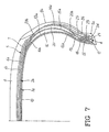
- FIG. 7 is a cross half-section of the tire made in accordance with the preceding figures.
- FIG. 8 is a diametrical half-section of a second embodiment of a tire in accordance with the present invention.
- FIG. 9 is a diametrical section of a further alternative embodiment of a tire in accordance with the invention.
- FIG. 10 shows, still in diametrical section, a fourth embodiment of the subject tire.
- a tire for vehicle wheels having a carcass structure 2 made with the method of the present invention has been generally identified by reference numeral 1 .
- the carcass structure 2 has a first and a second carcass plies 3 a , 3 b having a substantially toroidal configuration and engaged, through their circumferentially opposite edges, with a pair of annular anchoring structures 4 (only one of which is shown in the drawings) each of which, when the tire has been completed, is placed at the tire region usually identified as “bead”, to ensure anchoring of tire 1 to a corresponding mounting rim.
- a belt structure 5 comprising one or more belt strips 6 a , 6 b and 7 .
- a tread band 8 circumferentially overlaps the belt structure 5 and in said tread band, following a moulding operation carried out simultaneously with the tire polymerization, longitudinal and transverse grooves 8 a are formed and conveniently disposed so as to define a desired “tread pattern”.
- Tire 1 further comprises a pair of so-called “sidewalls” 9 , laterally applied to the carcass structure 2 on opposite sides thereof and comprising each a radially inner portion 9 a and a radially outer portion 9 b.
- the carcass structure 2 may be possibly coated on its inner walls, with a so-called “liner” 10 , essentially made of at least one layer of air-proof elastomer material adapted to ensure the air-tightness of the inflated tire.
- the toroidal support 11 may have reduced sizes as compared with those of the finished tire, according to a linear amount preferably included between 2% and 5% and measured, just as an indication, along the circumferential extension of the support itself at an equatorial plane X—X thereof which is coincident with the equatorial plane of the tire.
- the toroidal support 11 which is not described or illustrated in detail because it is not of particular importance to the aims of the invention, may for example consist either of a collapsible or dismountable drum or of an inflatable bladder suitably reinforced so that it may take and maintain the desired toroidal conformation under inflated conditions.
- manufacture of tire 1 first involves formation of the carcass structure 2 starting with possible formation of liner 10 .
- This liner 10 can be advantageously made by circumferentially winding up around the toroidal support 11 , at least one ribbon-like band 12 of an air-proof elastomer material, produced from an extruder and/or a calender located close to the toroidal support itself. As viewed from FIG. 1, winding of the ribbon-like band 12 substantially takes place in circumferential coils consecutively disposed in side by side relationship to follow the cross-section outline of the outer surface of the toroidal support 11 .
- cross-section outline it is herein intended a configuration exhibited by the half-section of the toroidal support 11 sectioned along a plane radial to a geometric rotation axis thereof, not shown in the drawings, which is coincident with the geometric axis of rotation of the tire and, therefore, of the carcass structure 2 being manufactured.
- the carcass ply or plies 3 a , 3 b are directly formed on the toroidal support 11 by depositing thereon, as better clarified in the following, strip-like lengths that, in the course of the present description, will be identified as axially inner lengths 13 , axially outer lengths 14 and axially intermediate lengths 15 respectively, depending on their positioning within the carcass structure 2 .
- the strip-like lengths 13 , 14 , 15 are advantageously formed of at least one continuous strip-like element preferably having a width included between 3 mm and 15 mm, essentially consisting of thread-like elements of textile or metallic material longitudinally disposed and at least partly incorporated into one or more layers of elastomer material.
- This continuous strip-like element can be advantageously produced from a calender or an extruder installed in the vicinity of the toroidal support 11 on which tire 1 is formed, to be guided to a deposition apparatus adapted to sequentially cut it to form the strip-like lengths 13 , 14 and 15 concurrently with deposition of said lengths onto the toroidal support itself.
- each strip-like length 13 , 14 , 15 is immediately followed by deposition of the length itself on the toroidal support 11 , giving the strip-like length a U-shaped conformation around the cross-section outline of said toroidal support, in such a manner that in the strip-like lengths 13 , 14 , 15 two side portions 13 a , 14 a , 15 a can be identified, which side portions radially extend towards the axis of the toroidal support 11 , at positions axially spaced apart from each other, as well as a crown portion 13 b , 14 b , 15 b extending at a radially outer position between the side portions.
- the toroidal support 11 can be driven in angular rotation according to a step-by-step movement in synchronism with operation of said deposition apparatus, in such a manner that each cutting action of each strip-like length 13 , 14 , 15 is followed by deposition of said length at a position circumferentially spaced apart from the previously laid down length 13 , 14 , 15 .
- rotation of the toroidal support 11 takes place following angular-movement steps to each of which corresponds a circumferential displacement that, depending on requirements, can be substantially equal to the width of each strip-like length 13 , 14 , 15 , or substantially equal to a multiple of this width. Consequently, the strip-like lengths 13 , 14 , 15 will be laid down following a circumferential distribution pitch substantially equal to their width, or to a multiply of this amount.
- the term “circumferential” refers to a circumference lying in the equatorial plane X—X and close to the outer surface of the toroidal support 11 .
- the angular movement of the toroidal support 11 takes place in such a manner that, by a first complete revolution of the toroidal support around its own axis, deposition of the axially inner lengths 13 takes place, which lengths are circumferentially distributed according to a circumferential pitch equal to twice the width of each of them. Therefore, as clearly viewed from FIG. 2, between two axially inner lengths 13 an empty space “S” is left that, at least at the crown portions 13 b of the lengths themselves, has a width substantially corresponding to that of said lengths.
- deposition of the axially inner strip-like lengths 13 may take place to an inclined orientation with respect to the circumferential extension direction of the toroidal support, at an angle included between 15° and 35°, for example.
- Adjustment of the deposition angle of the strip-like lengths can be obtained for example by suitably orienting the geometric rotation axis of the toroidal support with respect to the deposition apparatus.
- each axially inner length 13 may be advantageously provided to be carried out in deposition planes offset in parallel with respect to a meridian plane of the toroidal support 11 , as described in the Patent Application PCT/EP 99/09389 in the name of the same Applicant, contents of which are considered as herein completely incorporated.
- each side portion 13 a , 14 a , 15 a of each strip-like length 13 , 14 , 15 will form, with respect to a plane radial to the geometric axis of the toroidal support 11 passing through the transition point between the side portion itself and the respective crown portion 13 b , 14 b , 15 b , an angle of a different value from the angle formed by the same crown portion with respect to the same radial plane.
- each side portion 13 a , 14 a , 15 a will be given to each side portion 13 a , 14 a , 15 a relative to a direction radial to the geometric axis of the toroidal support 11 , while keeping the crown portion 13 b , 14 b , 15 b in a plane radial to the geometric axis itself.
- each resilient stiffening insert 16 preferably having a hardness included between 67 and 91 IRHD, has a cross-section outline substantially in the form of a lunette, gradually tapering towards a radially inner apex 16 a thereof, located close to the respective annular anchoring structure 4 , and towards a radially outer apex 16 b thereof, located, just as an indication, at a shoulder region of the tire, where transition between the side portions 13 a , 14 a , 15 a and crown portions 13 b , 14 b , 15 b of the strip-like lengths 13 , 14 , 15 takes place.
- each of the resilient stiffening inserts 16 can be directly formed against the side portions 13 a , by winding up a continuous strip of elastomer material, ejected from an extruder operating close to the toroidal support 11 in coils disposed in axial side by side relationship and/or radial superposition relationship.
- the continuous strip can have the final section conformation of the resilient stiffening insert 16 already on its coming out of the respective extruder.
- each resilient stiffening insert 16 please refer to that which is described in the Patent Application PCT/IT 99/00376 and/or in the Patent Application PCT/IT 99/00377, both in the name of the same Applicant.
- auxiliary portions 17 of the above-mentioned annular anchoring structures 4 are applied to the region close to each of the inner circumferential edges of the carcass ply 3 being manufactured.
- each of said auxiliary portions 17 comprises at least one auxiliary circumferentially-inextensible annular insert 18 , which is substantially in the form of a crown concentric with the geometric rotation axis of the toroidal support 11 and is located at a circumferentially inner position against end portions 13 c exhibited by the axially inner lengths 13 .
- the auxiliary annular insert 18 is preferably made up of at least one metallic strip-like element wound up in several substantially concentric coils 18 a .
- Coils 18 a can be defined either by a continuous spiral or by concentric rings formed with respective strip-like elements.
- auxiliary filling body 19 of elastomer material preferably of the thermoplastic type, of a hardness included between 80 and 90 IRHD, extending radially from the annular insert away from the geometric rotation axis of the toroidal support 11 and joining the respective resilient stiffening insert 16 at the inner apex 16 a of the latter.
- the auxiliary annular insert 18 is directly formed against the end f laps of the strip-like lengths 13 , forming coils 18 a through winding up of the strip-like element possibly with the aid of rollers or other convenient means acting against the surface of the toroidal support 11 .
- the auxiliary filling body 19 can be, in turn, directly formed against the auxiliary annular insert 18 , by applying a continuous strip of elastomer material coming out of an extruder located close to the toroidal support 11 for example, in the same manner as said with reference to formation of the resilient stiffening inserts 16 .
- formation of the first carcass ply 3 a is completed by deposition of the axially intermediate lengths 15 on the toroidal support 11 in the same manner as described for the axially inner lengths 13 .
- each intermediate length 15 is laid down in such a manner that its crown portion 15 b is circumferentially interposed between the crown portions 13 b of the axially inner lengths 13 , to fill the space “S” existing therebetween.
- the side portions 15 a of each intermediate length 15 are superposed, at an axially outer position, on the resilient stiffening elements 16 , and carry the end portions 15 c of the length itself in superposed relationship with the respective auxiliary portions 17 of the annular anchoring structures 4 , at an axially opposite position relative to the end portions 13 c of the axially inner lengths 13 .
- auxiliary resilient stiffening insert 20 is applied, said insert having a cross-section outline substantially in the form of a “lunette”, respectively tapering on opposite sides respectively towards a radially inner apex 20 a located close to the respective annular anchoring structure 4 and a radially outer apex 20 b located in the shoulder region of the tire.
- Each auxiliary insert 20 preferably made of elastomer material of a hardness included between 67 and 91 IRHD, can be advantageously directly formed against the side portions 15 a of the axially intermediate lengths 15 , in the same manner as described with reference to the manufacture of the resilient stiffening inserts 16 .
- each of the first portions 21 is preferably structured in the same manner as described with reference to the auxiliary portions 17 .
- each first portion 21 has a respective first circumferentially inextensible annular insert 22 formed of at least one respective strip-like element disposed in concentric coils 22 a to form a circular crown disposed coaxial with the carcass structure 2 and close to the inner circumferential edges of the carcass plies 3 a , 3 b.
- a first filling body 23 of elastomer material Combined with the first annular insert 22 , disposed against the end portions 15 c of the axially intermediate strip-like lengths 15 , is a first filling body 23 of elastomer material, having the same shape as the auxiliary filling body 19 .
- formation of the second carcass ply 3 b begins by deposition of the axially outer strip-like lengths 14 .
- This deposition step can be carried out in the same manner as described with reference to deposition of the axially 13 and intermediate 15 lengths or in a similar manner.
- the axially outer strip-like lengths 14 are laid down in crossed orientation relative to the inner 13 and intermediate 15 lengths, preferably at a symmetrically opposite angle with respect to the last-mentioned lengths, with reference to the circumferential extension direction of the carcass structure 2 .
- Deposition of the axially outer strip-like lengths 14 preferably takes place according to a circumferential pitch substantially equal to their width, in order to complete formation of the second carcass ply 3 b following carrying out of a single complete revolution by the toroidal support 11 around its rotation axis.
- each of the auxiliary resilient stiffening inserts 20 is interposed between the side portions 15 a of the axially intermediate lengths 15 and the side portions 14 a of the axially outer lengths 14 .
- each of the annular anchoring structures 4 provision is made for application of a second portion 24 against the end portions 14 c of the axially-outer strip-like sections 14 .
- each second portion 24 is essentially made up of at least one second annular insert 25 formed of coils 25 a disposed crownwise, in the same manner as said with reference to formation of the first annular insert 22 and the auxiliary annular insert 18 .
- each of the end portions 14 a of the axially outer lengths 14 is advantageously enclosed between the first and second portions 21 , 24 of the respective annular anchoring structure 4 .
- a second filling body 26 and a second auxiliary filling body can be associated with each second portion 24 , the second filling body being formed in the same manner as described with reference to the first filling body 23 and the second auxiliary filling body being designed to complete formation of the annular anchoring structure 4 .
- a belt structure 5 is usually applied to the carcass structure 2 .
- This belt structure 5 may be made in any manner convenient for a person skilled in the art and in the embodiment shown it essentially comprises a first and a second belt strips 6 a , 6 b formed of cords having a respectively crossed orientation.
- an auxiliary belt strip 7 superposed on the belt strips 6 a , 6 b is an auxiliary belt strip 7 , for instance obtained by winding up at least one continuous cord in substantially circumferential coils axially disposed in side by side relationship on said belt strips.
- the tread band 8 is applied to the belt structure 5 , whereas to the side portions of the carcass structure 2 are applied the sidewalls 9 , which are also obtained in any manner convenient for a person skilled in the art.
- Embodiments of a belt structure, sidewalls and a tread band that can be advantageously adopted for a complete accomplishment of tire 1 on the toroidal support 11 are described in document EP 919 406, in the name of the same Applicant.
- Tire 1 as manufactured is now ready to be submitted, possibly after removal from support 11 , to a vulcanization step that can be carried out in any known and conventional manner.
- FIGS. 8, 9 and 10 Shown in FIGS. 8, 9 and 10 are further examples of tires with a self-supporting structure 2 that can be obtained in accordance with the present invention.
- the tire shown in FIG. 8 has, in its carcass structure 2 , a single carcass ply 3 which is formed of axially inner lengths 13 and axially outer lengths 14 , in the absence of the intermediate lengths 15 described with reference to FIGS. 1 to 7 .
- Both the axially inner and axially outer lengths, 13 and 14 are laid down following a circumferential distribution pitch corresponding to a multiple of, more specifically twice, their width, the crown portions 14 b of the axially outer lengths 14 being each interposed between the crown portions 13 b and two axially inner lengths 13 that are circumferentially adjacent.
- resilient stiffening inserts 16 are applied against the side portions 13 a of the axially inner lengths 13 before carrying out deposition of the axially outer lengths 14 . Consequently, the resilient stiffening inserts 16 are interposed between the side portions 13 a , 14 a of the axially inner and axially outer lengths, 13 and 14 , once manufacture of the carcass ply 3 has been completed.
- auxiliary resilient stiffening inserts 20 are also provided to be arranged on the toroidal support 11 , for example by directly forming them against the opposite side surfaces of said support or against liner 10 previous formed on said surfaces. Consequently, in the completed carcass structure 2 the auxiliary resilient stiffening inserts 20 are located at an axially inner position relative to the side portions 14 a of the axially outer lengths 14 .
- Each of the annular anchoring structures 4 has a first portion 21 , formed of a first annular insert 22 provided with a first filling body 23 , which portion is axially interposed against the end portions 13 c , 14 c of the axially inner and outer lengths, 13 and 14 , as well as a second portion 24 comprising a second annular insert 25 applied at an axially outer position against the end portions 14 c of the axially outer lengths 14 and provided with a second filling body 26 .
- An auxiliary portion 17 of the anchoring structure 4 comprising an auxiliary annular insert 18 formed of coils 18 a , is disposed at an axially inner position against the end portions of the axially inner lengths 13 . This auxiliary portion 17 can be directly made or applied against the surfaces of the toroidal support 11 before deposition of the axially inner lengths 13 .
- the carcass structure 2 has a first carcass ply 3 a and a second carcass ply 3 b , formed of axially inner and axially outer lengths 13 and 14 , respectively, in the absence of the intermediate lengths 15 described with reference to FIGS. 1 to 7 .
- both axially inner and axially outer lengths, 13 and 14 are laid down following a circumferential distribution pitch substantially corresponding to their width.
- Application of the axially inner lengths 13 is preceded by formation of a pair of auxiliary resilient stiffening inserts 20 , located each against one of the opposite sides of the toroidal support 11 .
- the auxiliary resilient stiffening inserts 20 are therefore disposed at an axially inner position relative to the side portions 13 a of the axially inner lengths 13 , in the same manner as described with reference to FIG. 8 .
- Each annular anchoring structure 4 is made in the same manner as described with reference to the embodiment in FIG. 8 but, unlike the latter, the auxiliary annular insert 17 is formed after application of the axially inner lengths 13 , at an axially outer position against the end portions 13 c of said lengths 13 , so as to match the radially inner apex 16 a of the respective resilient stiffening insert 16 .
- each annular anchoring structure 4 should be partly interposed between the first annular insert 22 and the auxiliary insert 18 , as clearly shown in FIG. 9 .
- the carcass structure 2 has a first and a second carcass plies 3 a , 3 b .
- the first carcass ply 3 a is formed of axially inner lengths 13 and first axially intermediate lengths 15 , laid down following a circumferential pitch which is substantially twice their width and sequentially alternated with each other in the same manner as described with reference to the embodiment of the first carcass ply 3 a in the example shown in FIGS. 1 to 7 .
- Each resilient stiffening insert 16 is axially interposed between the side portions 13 a , 15 a belonging to the axially inner lengths 13 and the first axially intermediate lengths 15 , respectively.
- the second carcass ply 3 b is in turn formed of second axially intermediate lengths 31 laid down on the first carcass ply 3 a following a circumferential distribution pitch substantially corresponding to twice their width, and of axially outer lengths 14 , each alternated between two axially intermediate second lengths 31 .
- the second intermediate lengths 31 and the outer lengths 14 forming.
- the second carcass ply 3 b can be laid down, in case of need, following a crossed orientation with respect to the first intermediate lengths 15 and the inner lengths 13 forming the first carcass ply 3 a .
- the lengths belonging to the first and second carcass plies 3 a , 3 b respectively can be applied following deposition planes offset in parallel on respectively opposite sides relative to a meridian plane of the toroidal support 11 , to give a crossed orientation to the side portions of said lengths, while keeping the crown portions oriented according to planes substantially radial to said geometric axis.
- auxiliary resilient support insert 20 Interposed between the side portions 14 a , 31 a belonging to the outer lengths 14 and the second intermediate lengths 31 respectively, at each of the tire sidewalls 9 , is at least one auxiliary resilient support insert 20 .
- each of the annular anchoring structures 4 may comprise a first portion 21 axially interposed between the end portions 13 c , 15 c belonging to the inner lengths 13 and the first intermediate lengths 15 respectively, as well as a second portion 24 located at an axially outer position with respect to the axially outer lengths 14 .
- An auxiliary portion 17 of the annular anchoring structure 4 is also axially interposed between the end portions 13 c of the axially inner lengths 13 and the end portions 15 c of the first axially intermediate lengths 15 .
- the inner lengths 13 , intermediate lengths 15 and/or 31 and outer lengths 14 should cooperate in forming a single carcass ply.
- the lengths belonging to each of the inner 13 , intermediate 15 and/or 31 and outer 14 series are laid down following a circumferential distribution pitch which is a multiple of their width.
- the numerical factor that, multiplied by the width of each length, gives the value of the circumferential distribution pitch will correspond to the number of length series provided in the formation of the single or of each carcass ply. For instance, if three length series are provided, an inner, intermediate and outer series, 13 , 15 and 14 respectively, the circumferential distribution pitch of the lengths of each series will correspond to three times their width.
- the axially inner lengths 13 should be laid down following a circumferential distribution pitch corresponding to a multiple of their width.
- the axially intermediate lengths 15 are applied following a circumferential distribution pitch corresponding to a multiple of their width, each with the respective crown portion 15 b disposed circumferentially close to the crown portion 13 b of one of the axially inner lengths 13 .
- each axially outer length 14 has its crown portion 14 b in circumferential side by side relationship between the crown portion 13 b of one of the axially inner lengths 13 and the crown portion 15 b of one of the axially intermediate lengths 15 , so as to define the carcass ply with the above mentioned lengths.
- the crown portions 13 b , 15 b and 14 b of the individual lengths are sequentially alternated in mutual side by side relationship along one and the same circumferential line, whereas the respective side portions 13 a , 15 a , 14 a are axially offset with respect to each other to house one or more resilient stiffening inserts 16 , 20 in the spaces existing between the side portions of the inner 13 and intermediate 15 lengths, as well as between the side portions of the intermediate 15 and outer 14 lengths.
- the holding or containment effect exerted by the carcass ply or plies 3 a , 3 b around the resilient stiffening inserts 16 , 20 can be controlled, depending on requirements.
- the carcass plies 3 a , 3 b can be manufactured and disposed so as to form a sort of container completely closed around at least one of the resilient stiffening inserts 16 , 20 , by making the plies themselves, for example, with the axially inner lengths 13 and axially outer lengths 14 laid down following a pitch corresponding to their width, and causing the end portions 13 c , 14 c of the lengths to mutually match within the annular anchoring structures 4 .
- the elastomer material forming the stiffening insert enclosed between the plies 3 a , 3 b behaves like a sort of hydrostatic i.e. an incompressible liquid, the deformability of which is strictly correlated with the deformability of the container holding it.
- the inner lengths 13 and outer lengths 14 for example, laid down in an alternated sequence and in subsequent steps after interposition of at least one resilient stiffening insert 16 , it is possible to create, in an original manner, a sort of container around the insert itself, which container is partly open on its axially opposite sides.
- the stiffening insert 16 it will be possible for the stiffening insert 16 to expand in the free spaces existing, on each of its axially opposite sides, between the side portions of the inner 13 and outer 14 lengths laid down following a pitch which is twice their width.
- the modulus of elasticity of the elastomer material used in the stiffening inserts 16 being the same, it is reduced the stiffening degree given to the carcass structure 2 on the whole.
- the amount of this reduction in the stiffening degree can be advantageously regulated depending on requirements, by modifying the solid space/void space ratio determined by the side portions of the strip-like lengths on the axially opposite sides of the stiffening insert 16 and/or 20 , just as an indication between a maximum value to be obtained, as above said, through accomplishment of two carcass plies 3 a , 3 b each formed of a single series of strip-like lengths 13 , 14 laid down following a pitch corresponding to their width, and a minimum value to be obtained through use, as in the example in FIG. 8, of a single carcass ply 3 a formed of two series of lengths 13 , 14 laid down in alternated sequence.
- the containment degree of the deformations of the resilient stiffening inserts 16 , 20 can be also regulated by modifying the construction plan of the annular anchoring structures 4 depending on requirements, in order to modify the axial distance between the end portions 13 c , 14 c , 15 c of the strip-like lengths, so as to offer an additional outlet to the deformations of the stiffening inserts 16 , 20 towards the tire bead.
- the invention as compared with the known art enables introduction of new variables having an influence on the tire behaviour, particularly in connection with its rigidity both under inflated conditions and under deflated conditions.
- the invention also enables manufacture of a self-supporting tire in which the subject carcass structure can be obtained directly on a toroidal support on which the whole tire can be advantageously formed. In this way all problems connected with the manufacture, storage and management of semifinished products which are common to the manufacturing processes of traditional conception are eliminated.
Landscapes
- Engineering & Computer Science (AREA)
- Mechanical Engineering (AREA)
- Tires In General (AREA)
- Tyre Moulding (AREA)
Priority Applications (1)
| Application Number | Priority Date | Filing Date | Title |
|---|---|---|---|
| US09/979,985 US6814119B2 (en) | 2000-03-31 | 2001-05-27 | Self-supporting tire for a vehicle wheel and method for manufacturing the tire |
Applications Claiming Priority (6)
| Application Number | Priority Date | Filing Date | Title |
|---|---|---|---|
| EP00830242 | 2000-03-31 | ||
| EP00830242.4 | 2000-03-31 | ||
| EP00830242 | 2000-03-31 | ||
| US20292100P | 2000-05-09 | 2000-05-09 | |
| PCT/EP2001/003468 WO2001072534A1 (fr) | 2000-03-31 | 2001-03-27 | Pneumatique auto-porteur de roues de vehicules et son procede de production |
| US09/979,985 US6814119B2 (en) | 2000-03-31 | 2001-05-27 | Self-supporting tire for a vehicle wheel and method for manufacturing the tire |
Publications (2)
| Publication Number | Publication Date |
|---|---|
| US20020157753A1 US20020157753A1 (en) | 2002-10-31 |
| US6814119B2 true US6814119B2 (en) | 2004-11-09 |
Family
ID=26074137
Family Applications (1)
| Application Number | Title | Priority Date | Filing Date |
|---|---|---|---|
| US09/979,985 Expired - Lifetime US6814119B2 (en) | 2000-03-31 | 2001-05-27 | Self-supporting tire for a vehicle wheel and method for manufacturing the tire |
Country Status (13)
| Country | Link |
|---|---|
| US (1) | US6814119B2 (fr) |
| EP (1) | EP1181160B1 (fr) |
| JP (1) | JP2003528761A (fr) |
| CN (1) | CN1195648C (fr) |
| AR (1) | AR028907A1 (fr) |
| AT (1) | ATE301553T1 (fr) |
| AU (1) | AU4651101A (fr) |
| BR (1) | BR0105388A (fr) |
| DE (1) | DE60112520T2 (fr) |
| EG (1) | EG23152A (fr) |
| ES (1) | ES2247086T3 (fr) |
| TW (1) | TW500671B (fr) |
| WO (1) | WO2001072534A1 (fr) |
Cited By (9)
| Publication number | Priority date | Publication date | Assignee | Title |
|---|---|---|---|---|
| US20020170647A1 (en) * | 1999-11-18 | 2002-11-21 | Michelin Recherche Et Technique S.A. | Tire with low zone comprising a concentration of cords |
| US20030051787A1 (en) * | 2000-01-28 | 2003-03-20 | Renato Caretta | Carcass structure for tyres and a tyre provided with such a carcass structure |
| US20040055688A1 (en) * | 1998-10-30 | 2004-03-25 | Pirelli Pneumatici S.P.A. | Tyre for a vehicle wheel |
| US20040074580A1 (en) * | 2000-12-22 | 2004-04-22 | Renato Caretta | Self- supporting tyre for vehicle wheels and method for manufacturing the same |
| US20050034800A1 (en) * | 2001-09-28 | 2005-02-17 | Maurizio Boiocchi | Self-supporting tyre for vehicle wheels, and method of manufacturing the same |
| US20050081977A1 (en) * | 1998-12-23 | 2005-04-21 | Pirelli Pneumatici S.P.A. | Tyre for a vehicle wheel |
| WO2006071228A1 (fr) * | 2004-12-29 | 2006-07-06 | Michelin Recherche Et Technique S.A. | Pneumatique a mobilite accrue presentant une configuration asymetrique de materiaux entre les carcasses |
| US20140083591A1 (en) * | 2012-09-24 | 2014-03-27 | Sumitomo Rubber Industries, Ltd. | Pneumatic tire |
| US20150239189A1 (en) * | 2012-08-24 | 2015-08-27 | Sumitomo Rubber Industries Ltd. | Manufacturing method for pneumatic tire and pneumatic tire |
Families Citing this family (7)
| Publication number | Priority date | Publication date | Assignee | Title |
|---|---|---|---|---|
| CN100427301C (zh) * | 2002-04-19 | 2008-10-22 | 株式会社普利司通 | 漏气保用轮胎及其制造方法 |
| JP4593478B2 (ja) * | 2004-01-13 | 2010-12-08 | 株式会社ブリヂストン | タイヤの製造方法 |
| JP4695429B2 (ja) * | 2004-11-11 | 2011-06-08 | 住友ゴム工業株式会社 | 空気入りタイヤ及びその製造方法 |
| JP5033911B2 (ja) * | 2007-04-23 | 2012-09-26 | ピレリ・タイヤ・ソチエタ・ペル・アツィオーニ | 車両用タイヤの製造方法において少なくとも1つの弾性要素を配置する方法、車両用タイヤの製造方法、及び少なくとも1つの弾性要素を配置するための装置 |
| EP2326491B1 (fr) * | 2008-08-11 | 2012-04-25 | PIRELLI TYRE S.p.A. | Procédé de construction d'un pneu vert pour roues de véhicule et pneu construit selon ledit procédé |
| JP6043554B2 (ja) * | 2012-09-10 | 2016-12-14 | 住友ゴム工業株式会社 | 空気入りタイヤ |
| EP2865547B1 (fr) * | 2013-10-22 | 2016-04-13 | Sumitomo Rubber Industries Limited | Pneu |
Citations (17)
| Publication number | Priority date | Publication date | Assignee | Title |
|---|---|---|---|---|
| US2966933A (en) | 1957-03-14 | 1961-01-03 | Michelin & Cie | Beads for pneumatic tires |
| US3072171A (en) | 1959-05-08 | 1963-01-08 | Dunlop Rubber Co | Pneumatic tyres |
| US3240250A (en) | 1964-06-11 | 1966-03-15 | Nat Standard Co | Pneumatic tires |
| US4067372A (en) | 1974-02-26 | 1978-01-10 | Pneumatiques Caoutchouc Manufacture Et Plastiques Kleber-Colombes | Radial tire having sidewalls reinforced with a rubbery mixture having a high modulus |
| GB2087805A (en) | 1980-11-24 | 1982-06-03 | Goodyear Tire & Rubber | Pneumatic safety tire |
| EP0475258A1 (fr) | 1990-09-14 | 1992-03-18 | PIRELLI COORDINAMENTO PNEUMATICI S.p.A. | Carcasse autoportante pour pneumatiques de véhicule à moteur |
| EP0542252A1 (fr) | 1991-11-15 | 1993-05-19 | PIRELLI COORDINAMENTO PNEUMATICI S.p.A. | Pneumatique autoportant pour roues de véhicules à moteur incorporant des inserts de soutien élastiques dans les flancs |
| US5368082A (en) | 1992-09-30 | 1994-11-29 | The Goodyear Tire & Rubber Company | Radial ply pneumatic tire |
| EP0919406A1 (fr) | 1997-11-28 | 1999-06-02 | Pirelli Pneumatici Societa' Per Azioni | Bandage pneumatique pour roues de véhicules |
| EP0928680A1 (fr) | 1997-12-30 | 1999-07-14 | Pirelli Pneumatici Societa' Per Azioni | Procédé de fabrication de bandages pneumatiques pour roues de véhicule |
| EP0928702A1 (fr) | 1997-12-30 | 1999-07-14 | Pirelli Pneumatici Societa' Per Azioni | Bandage pneumatique pour roues de véhicule |
| EP0976535A2 (fr) | 1998-07-31 | 2000-02-02 | PIRELLI PNEUMATICI Società per Azioni | Procédé de fabrication d'une carcasse pour pneu et carcasse ainsi fabriquée |
| US6026878A (en) * | 1997-05-29 | 2000-02-22 | The Goodyear Tire & Rubber Company | Inextensible high temperature resistant tire |
| WO2000035666A1 (fr) | 1998-12-17 | 2000-06-22 | Pirelli Pneumatici S.P.A. | Procede et appareil pour fabriquer les composants d'un pneu pour les roues d'un vehicule |
| WO2000038906A1 (fr) | 1998-12-23 | 2000-07-06 | Pirelli Pneumatici S.P.A. | Procede de fabrication d'une carcasse pour pneus et carcasse ainsi obtenue |
| WO2000073093A1 (fr) * | 1999-05-27 | 2000-12-07 | Michelin Recherche Et Technique | Pneumatique a affaissement limite comprenant un chemin de carcasse optimise |
| WO2001036185A1 (fr) | 1999-11-19 | 2001-05-25 | Pirelli Pneumatici S.P.A. | Procede de fabrication de composants elastomeres d'un pneumatique destine aux roues d'un vehicule |
-
2001
- 2001-03-27 AT AT01919397T patent/ATE301553T1/de not_active IP Right Cessation
- 2001-03-27 JP JP2001570467A patent/JP2003528761A/ja active Pending
- 2001-03-27 ES ES01919397T patent/ES2247086T3/es not_active Expired - Lifetime
- 2001-03-27 BR BR0105388-4A patent/BR0105388A/pt active Search and Examination
- 2001-03-27 EP EP01919397A patent/EP1181160B1/fr not_active Expired - Lifetime
- 2001-03-27 AU AU46511/01A patent/AU4651101A/en not_active Abandoned
- 2001-03-27 CN CNB018007821A patent/CN1195648C/zh not_active Expired - Lifetime
- 2001-03-27 WO PCT/EP2001/003468 patent/WO2001072534A1/fr active IP Right Grant
- 2001-03-27 DE DE60112520T patent/DE60112520T2/de not_active Expired - Lifetime
- 2001-03-30 AR ARP010101540A patent/AR028907A1/es active IP Right Grant
- 2001-03-31 EG EG20010323A patent/EG23152A/xx active
- 2001-04-19 TW TW090109412A patent/TW500671B/zh not_active IP Right Cessation
- 2001-05-27 US US09/979,985 patent/US6814119B2/en not_active Expired - Lifetime
Patent Citations (17)
| Publication number | Priority date | Publication date | Assignee | Title |
|---|---|---|---|---|
| US2966933A (en) | 1957-03-14 | 1961-01-03 | Michelin & Cie | Beads for pneumatic tires |
| US3072171A (en) | 1959-05-08 | 1963-01-08 | Dunlop Rubber Co | Pneumatic tyres |
| US3240250A (en) | 1964-06-11 | 1966-03-15 | Nat Standard Co | Pneumatic tires |
| US4067372A (en) | 1974-02-26 | 1978-01-10 | Pneumatiques Caoutchouc Manufacture Et Plastiques Kleber-Colombes | Radial tire having sidewalls reinforced with a rubbery mixture having a high modulus |
| GB2087805A (en) | 1980-11-24 | 1982-06-03 | Goodyear Tire & Rubber | Pneumatic safety tire |
| EP0475258A1 (fr) | 1990-09-14 | 1992-03-18 | PIRELLI COORDINAMENTO PNEUMATICI S.p.A. | Carcasse autoportante pour pneumatiques de véhicule à moteur |
| EP0542252A1 (fr) | 1991-11-15 | 1993-05-19 | PIRELLI COORDINAMENTO PNEUMATICI S.p.A. | Pneumatique autoportant pour roues de véhicules à moteur incorporant des inserts de soutien élastiques dans les flancs |
| US5368082A (en) | 1992-09-30 | 1994-11-29 | The Goodyear Tire & Rubber Company | Radial ply pneumatic tire |
| US6026878A (en) * | 1997-05-29 | 2000-02-22 | The Goodyear Tire & Rubber Company | Inextensible high temperature resistant tire |
| EP0919406A1 (fr) | 1997-11-28 | 1999-06-02 | Pirelli Pneumatici Societa' Per Azioni | Bandage pneumatique pour roues de véhicules |
| EP0928680A1 (fr) | 1997-12-30 | 1999-07-14 | Pirelli Pneumatici Societa' Per Azioni | Procédé de fabrication de bandages pneumatiques pour roues de véhicule |
| EP0928702A1 (fr) | 1997-12-30 | 1999-07-14 | Pirelli Pneumatici Societa' Per Azioni | Bandage pneumatique pour roues de véhicule |
| EP0976535A2 (fr) | 1998-07-31 | 2000-02-02 | PIRELLI PNEUMATICI Società per Azioni | Procédé de fabrication d'une carcasse pour pneu et carcasse ainsi fabriquée |
| WO2000035666A1 (fr) | 1998-12-17 | 2000-06-22 | Pirelli Pneumatici S.P.A. | Procede et appareil pour fabriquer les composants d'un pneu pour les roues d'un vehicule |
| WO2000038906A1 (fr) | 1998-12-23 | 2000-07-06 | Pirelli Pneumatici S.P.A. | Procede de fabrication d'une carcasse pour pneus et carcasse ainsi obtenue |
| WO2000073093A1 (fr) * | 1999-05-27 | 2000-12-07 | Michelin Recherche Et Technique | Pneumatique a affaissement limite comprenant un chemin de carcasse optimise |
| WO2001036185A1 (fr) | 1999-11-19 | 2001-05-25 | Pirelli Pneumatici S.P.A. | Procede de fabrication de composants elastomeres d'un pneumatique destine aux roues d'un vehicule |
Cited By (20)
| Publication number | Priority date | Publication date | Assignee | Title |
|---|---|---|---|---|
| US20040055688A1 (en) * | 1998-10-30 | 2004-03-25 | Pirelli Pneumatici S.P.A. | Tyre for a vehicle wheel |
| US7096910B2 (en) * | 1998-10-30 | 2006-08-29 | Pirelli Pneumatici S.P.A. | Tire for a vehicle wheel |
| US7416007B2 (en) * | 1998-12-23 | 2008-08-26 | Pirelli Pneumatici S.P.A. | Tyre for a vehicle wheel |
| US20050081977A1 (en) * | 1998-12-23 | 2005-04-21 | Pirelli Pneumatici S.P.A. | Tyre for a vehicle wheel |
| US20020170647A1 (en) * | 1999-11-18 | 2002-11-21 | Michelin Recherche Et Technique S.A. | Tire with low zone comprising a concentration of cords |
| US7406992B2 (en) | 1999-11-18 | 2008-08-05 | Michelin Recherche Et Technique S.A. | Tire with low zone comprising a concentration of cords |
| US6973950B2 (en) * | 1999-11-18 | 2005-12-13 | Michelin Recherche Et Technique S.A. | Tire with low zone comprising a concentration of cords |
| US8037912B2 (en) | 1999-11-18 | 2011-10-18 | Michelin Recherche Et Technique S.A. | Tire with low zone comprising a concentration of cords |
| US20060070693A1 (en) * | 1999-11-18 | 2006-04-06 | Pereira Pedro C | Tire with low zone comprising a concentration of cords |
| US20080178980A1 (en) * | 1999-11-18 | 2008-07-31 | Michelin Recherche Et Techniquie S.A. | Tire with low zone comprising a concentration of cords |
| US6899154B2 (en) * | 2000-01-28 | 2005-05-31 | Pirelli Pneumatici S.P.A. | Carcass structure for a tire and tire provided with the carcass structure |
| US20030051787A1 (en) * | 2000-01-28 | 2003-03-20 | Renato Caretta | Carcass structure for tyres and a tyre provided with such a carcass structure |
| US7025846B2 (en) | 2000-12-22 | 2006-04-11 | Pirelli Pneumatici S.P.A. | Self-supporting tyre for vehicle wheels and method for manufacturing the same |
| US20040074580A1 (en) * | 2000-12-22 | 2004-04-22 | Renato Caretta | Self- supporting tyre for vehicle wheels and method for manufacturing the same |
| US7096908B2 (en) * | 2001-09-28 | 2006-08-29 | Pirelli Pneumatici S.P.A. | Self-supporting tyre for a vehicle wheel, and method of making the tyre |
| US20050034800A1 (en) * | 2001-09-28 | 2005-02-17 | Maurizio Boiocchi | Self-supporting tyre for vehicle wheels, and method of manufacturing the same |
| WO2006071228A1 (fr) * | 2004-12-29 | 2006-07-06 | Michelin Recherche Et Technique S.A. | Pneumatique a mobilite accrue presentant une configuration asymetrique de materiaux entre les carcasses |
| US20150239189A1 (en) * | 2012-08-24 | 2015-08-27 | Sumitomo Rubber Industries Ltd. | Manufacturing method for pneumatic tire and pneumatic tire |
| US20140083591A1 (en) * | 2012-09-24 | 2014-03-27 | Sumitomo Rubber Industries, Ltd. | Pneumatic tire |
| US9272583B2 (en) * | 2012-09-24 | 2016-03-01 | Sumitomo Rubber Industries, Ltd. | Pneumatic tire |
Also Published As
| Publication number | Publication date |
|---|---|
| AU4651101A (en) | 2001-10-08 |
| BR0105388A (pt) | 2002-02-19 |
| EP1181160B1 (fr) | 2005-08-10 |
| ES2247086T3 (es) | 2006-03-01 |
| JP2003528761A (ja) | 2003-09-30 |
| EP1181160A1 (fr) | 2002-02-27 |
| ATE301553T1 (de) | 2005-08-15 |
| AR028907A1 (es) | 2003-05-28 |
| CN1366495A (zh) | 2002-08-28 |
| TW500671B (en) | 2002-09-01 |
| DE60112520T2 (de) | 2006-06-08 |
| US20020157753A1 (en) | 2002-10-31 |
| WO2001072534A1 (fr) | 2001-10-04 |
| CN1195648C (zh) | 2005-04-06 |
| EG23152A (en) | 2004-05-31 |
| DE60112520D1 (de) | 2005-09-15 |
Similar Documents
| Publication | Publication Date | Title |
|---|---|---|
| JP4615728B2 (ja) | タイヤ用カーカスの製造方法およびそれにより得られるカーカス | |
| US6814119B2 (en) | Self-supporting tire for a vehicle wheel and method for manufacturing the tire | |
| US10124551B2 (en) | Split ply tires and bead area monocomponents | |
| JP2002517335A (ja) | 車両の車輪のためのタイヤを製造する方法、当該方法により得ることのできるタイヤ及び当該タイヤを有する車両 | |
| US7025846B2 (en) | Self-supporting tyre for vehicle wheels and method for manufacturing the same | |
| US8770245B2 (en) | Tyre for two-wheeled vehicle and process for manufacturing the same | |
| US7096908B2 (en) | Self-supporting tyre for a vehicle wheel, and method of making the tyre | |
| US20110146871A1 (en) | Self-supporting pneumatic tire | |
| CA1162134A (fr) | Pneumatique, et methode de fabrication connexe | |
| US20030217801A1 (en) | Three ply layer turn-up for pneumatic tire | |
| US7249622B2 (en) | Tire with deep tread grooves | |
| US20110308685A1 (en) | Tyre for two-wheeled vehicle and process for manufacturing the same | |
| US20020124935A1 (en) | Carcass structure for vehicle-wheel tyres and its method of manufacturing | |
| EP1124699B1 (fr) | Structure de carcasse pour pneumatiques de roues de vehicule et son procede de fabrication | |
| EP0894614B1 (fr) | Procédé pour la fabrication d'un bandage pneumatique pour roue de véhicule | |
| RU2247034C1 (ru) | Самоподдерживаемая шина для колес транспортного средства и способ ее изготовления | |
| EP0894645B1 (fr) | Bandage pneumatique pour roues de véhicules et jante destinée à être utilisée en combinaison avec ledit bandage | |
| EP1525105A1 (fr) | Pneumatique pour roue de vehicule a structure de bourrelet renforcee |
Legal Events
| Date | Code | Title | Description |
|---|---|---|---|
| AS | Assignment |
Owner name: PIRELLI PNEUMATICI S.P.A., ITALY Free format text: ASSIGNMENT OF ASSIGNORS INTEREST;ASSIGNORS:CARETTA, RENATO;MISANI, PIERANGELO;FRIZIANI, LUCA;REEL/FRAME:012450/0116 Effective date: 20011113 |
|
| STCF | Information on status: patent grant |
Free format text: PATENTED CASE |
|
| CC | Certificate of correction | ||
| FPAY | Fee payment |
Year of fee payment: 4 |
|
| FPAY | Fee payment |
Year of fee payment: 8 |
|
| FPAY | Fee payment |
Year of fee payment: 12 |