US6782973B1 - Device for climbing on extended support elements, such as ropes, with releasable automatically reclamping clasps - Google Patents
Device for climbing on extended support elements, such as ropes, with releasable automatically reclamping clasps Download PDFInfo
- Publication number
- US6782973B1 US6782973B1 US09/890,495 US89049501A US6782973B1 US 6782973 B1 US6782973 B1 US 6782973B1 US 89049501 A US89049501 A US 89049501A US 6782973 B1 US6782973 B1 US 6782973B1
- Authority
- US
- United States
- Prior art keywords
- clasp
- weight
- bearing element
- clasps
- yoke
- Prior art date
- Legal status (The legal status is an assumption and is not a legal conclusion. Google has not performed a legal analysis and makes no representation as to the accuracy of the status listed.)
- Expired - Fee Related
Links
Images


Classifications
-
- A—HUMAN NECESSITIES
- A63—SPORTS; GAMES; AMUSEMENTS
- A63B—APPARATUS FOR PHYSICAL TRAINING, GYMNASTICS, SWIMMING, CLIMBING, OR FENCING; BALL GAMES; TRAINING EQUIPMENT
- A63B27/00—Apparatus for climbing poles, trees, or the like
-
- A—HUMAN NECESSITIES
- A47—FURNITURE; DOMESTIC ARTICLES OR APPLIANCES; COFFEE MILLS; SPICE MILLS; SUCTION CLEANERS IN GENERAL
- A47L—DOMESTIC WASHING OR CLEANING; SUCTION CLEANERS IN GENERAL
- A47L3/00—Safety devices for use in window-cleaning
- A47L3/02—Cages; Platforms
-
- A—HUMAN NECESSITIES
- A62—LIFE-SAVING; FIRE-FIGHTING
- A62B—DEVICES, APPARATUS OR METHODS FOR LIFE-SAVING
- A62B1/00—Devices for lowering persons from buildings or the like
- A62B1/06—Devices for lowering persons from buildings or the like by making use of rope-lowering devices
- A62B1/14—Devices for lowering persons from buildings or the like by making use of rope-lowering devices with brakes sliding on the rope
-
- A—HUMAN NECESSITIES
- A62—LIFE-SAVING; FIRE-FIGHTING
- A62B—DEVICES, APPARATUS OR METHODS FOR LIFE-SAVING
- A62B35/00—Safety belts or body harnesses; Similar equipment for limiting displacement of the human body, especially in case of sudden changes of motion
- A62B35/0081—Equipment which can travel along the length of a lifeline, e.g. travelers
-
- A—HUMAN NECESSITIES
- A63—SPORTS; GAMES; AMUSEMENTS
- A63B—APPARATUS FOR PHYSICAL TRAINING, GYMNASTICS, SWIMMING, CLIMBING, OR FENCING; BALL GAMES; TRAINING EQUIPMENT
- A63B21/00—Exercising apparatus for developing or strengthening the muscles or joints of the body by working against a counterforce, with or without measuring devices
- A63B21/40—Interfaces with the user related to strength training; Details thereof
- A63B21/4001—Arrangements for attaching the exercising apparatus to the user's body, e.g. belts, shoes or gloves specially adapted therefor
- A63B21/4007—Arrangements for attaching the exercising apparatus to the user's body, e.g. belts, shoes or gloves specially adapted therefor to the chest region, e.g. to the back chest
-
- A—HUMAN NECESSITIES
- A63—SPORTS; GAMES; AMUSEMENTS
- A63B—APPARATUS FOR PHYSICAL TRAINING, GYMNASTICS, SWIMMING, CLIMBING, OR FENCING; BALL GAMES; TRAINING EQUIPMENT
- A63B21/00—Exercising apparatus for developing or strengthening the muscles or joints of the body by working against a counterforce, with or without measuring devices
- A63B21/40—Interfaces with the user related to strength training; Details thereof
- A63B21/4001—Arrangements for attaching the exercising apparatus to the user's body, e.g. belts, shoes or gloves specially adapted therefor
- A63B21/4009—Arrangements for attaching the exercising apparatus to the user's body, e.g. belts, shoes or gloves specially adapted therefor to the waist
-
- A—HUMAN NECESSITIES
- A63—SPORTS; GAMES; AMUSEMENTS
- A63B—APPARATUS FOR PHYSICAL TRAINING, GYMNASTICS, SWIMMING, CLIMBING, OR FENCING; BALL GAMES; TRAINING EQUIPMENT
- A63B21/00—Exercising apparatus for developing or strengthening the muscles or joints of the body by working against a counterforce, with or without measuring devices
- A63B21/40—Interfaces with the user related to strength training; Details thereof
- A63B21/4001—Arrangements for attaching the exercising apparatus to the user's body, e.g. belts, shoes or gloves specially adapted therefor
- A63B21/4011—Arrangements for attaching the exercising apparatus to the user's body, e.g. belts, shoes or gloves specially adapted therefor to the lower limbs
-
- A—HUMAN NECESSITIES
- A63—SPORTS; GAMES; AMUSEMENTS
- A63B—APPARATUS FOR PHYSICAL TRAINING, GYMNASTICS, SWIMMING, CLIMBING, OR FENCING; BALL GAMES; TRAINING EQUIPMENT
- A63B29/00—Apparatus for mountaineering
- A63B29/02—Mountain guy-ropes or accessories, e.g. avalanche ropes; Means for indicating the location of accidentally buried, e.g. snow-buried, persons
-
- A—HUMAN NECESSITIES
- A62—LIFE-SAVING; FIRE-FIGHTING
- A62B—DEVICES, APPARATUS OR METHODS FOR LIFE-SAVING
- A62B35/00—Safety belts or body harnesses; Similar equipment for limiting displacement of the human body, especially in case of sudden changes of motion
- A62B35/0043—Lifelines, lanyards, and anchors therefore
- A62B35/005—Vertical lifelines
-
- A—HUMAN NECESSITIES
- A63—SPORTS; GAMES; AMUSEMENTS
- A63B—APPARATUS FOR PHYSICAL TRAINING, GYMNASTICS, SWIMMING, CLIMBING, OR FENCING; BALL GAMES; TRAINING EQUIPMENT
- A63B2208/00—Characteristics or parameters related to the user or player
- A63B2208/02—Characteristics or parameters related to the user or player posture
- A63B2208/0228—Sitting on the buttocks
- A63B2208/0238—Sitting on the buttocks with stretched legs, like on a bed
-
- A—HUMAN NECESSITIES
- A63—SPORTS; GAMES; AMUSEMENTS
- A63B—APPARATUS FOR PHYSICAL TRAINING, GYMNASTICS, SWIMMING, CLIMBING, OR FENCING; BALL GAMES; TRAINING EQUIPMENT
- A63B2208/00—Characteristics or parameters related to the user or player
- A63B2208/02—Characteristics or parameters related to the user or player posture
- A63B2208/0285—Hanging
- A63B2208/029—Hanging upright
-
- A—HUMAN NECESSITIES
- A63—SPORTS; GAMES; AMUSEMENTS
- A63B—APPARATUS FOR PHYSICAL TRAINING, GYMNASTICS, SWIMMING, CLIMBING, OR FENCING; BALL GAMES; TRAINING EQUIPMENT
- A63B2210/00—Space saving
- A63B2210/50—Size reducing arrangements for stowing or transport
Abstract
The device for climbing a pair of ropes (1) includes releasable upper and lower clasps (4,6) for each rope that clamp in response to a downward force acting thereon but relieve when the downward force is relieved and connecting elements for holding a climber, including a seat (7, 12) or harness (23), Each releasable clasp (4,6) has a housing (21); a yoke (3) in the housing (21) provided with an interior space having beveled inclines widening downward; cotters (10) positioned on opposite sides of the rope (1) in the inner space; rollers (11) arranged movably, but securably, between the cotters (10) and the beveled inclines; a compression spring (20) bearing on an upper end of the yoke (3); and a time servo-component (9) arranged at a lower end of the yoke. The time servo-components (9) act on the yokes so that the clasps (4,6), when relieved, automatically clamp the ropes again after a predetermined time interval.
Description
1. Field of the Invention
The present invention relates to equipment for climbing a flexible or rigid weight-bearing element, such as rope.
2. Description of the Related Art
Devices for climbing on ropes with grips are known from DE 19726035 A1 and DE 19643455. The disadvantages of the technical solutions provided in these patent applications is that the requirements for greater functional safety and easy ascent and descent for the climbing person can only be attained with great technical effort.
The task of the present invention is therefore to provide complete functional security and energy-saving climbing, especially for persons on the ropes or rigid structures.
According to one aspect of the present invention the device for climbing at least one flexible or rigid weight-bearing element, such as a rope, comprises
releasable clasps each including means for clamping the at least one weight-bearing element in response to a downward force acting thereon and means for releasing the at least one weight-bearing element when the downward force is relieved; and
connecting means attached to the clasps for holding the climber so that he or she is able to apply and relieve the downward force by shifting his or her weight;
wherein each clasp includes a time servo-component acting on the means for clamping the at least one weight-bearing element to again clamp the at least one weight-bearing element when a predetermined time interval starting from relief of the downward pressure expires.
In various embodiments of the invention the time servo-component is an elastic rubber member, a hydraulic spring or a pneumatic spring and the means for clamping the at least one weight-bearing element comprises inclined bevels or a yoke that responds to the time servo-component so that the clasp associated with the time servo-component releases.
In preferred embodiments of the invention the clasps include at least one upper clasp and at least one lower clasp. The lower clasp or clasps are arranged below the upper clasp or clasps on the at least one weight-bearing element.
In some embodiments the connecting means includes a solid seat and the at least one upper clasp is located at the solid seat. Preferably the at least one weight-bearing element consists of two ropes. Frame handles associated with each rope are attached to opposite sides of the solid seat. Guide wheels are provided at upper ends of the frame handles over which the ropes are guided. A tension spring is arranged between the respective lower and upper clasp for each rope through which it passes to the feet of the climber. Pedal levers are pivotally attached to the bottom ends of the frame handles and connected with the upper clasps so as to be able to release them.
In other embodiments of the device the connecting means for holding the climber includes at least one system belt and a movable seat, which is attached to the at least one upper clasp by the at least one system belt, so that a connection between the movable seat and the at least one upper clasp is pressure-stable in a longitudinal direction of the at least one system belt. The at least one system belt is preferably form-locked in the at least one upper clasp so that the at least one system belt cannot slip out of the at least one upper clasp. The at least one lower clasp preferably includes the yoke and a pulling element attached to it, which comprises manual means for releasing the downward pressure. In these preferred embodiments tension springs are arranged between the movable seat and the at least one lower clasp and additional tension springs are arranged between the movable seat and the at least one upper clasp, the at least one weight-bearing element passing through the tension springs.
In its preferred form each clasp includes a housing; the yoke mounted in the housing and provided with an interior space having inner contours with beveled inclines widening downward in the inner space; cotters positioned on opposite sides of the at least one weight-bearing element in the inner space; rollers arranged movably, but securably, between cotters and inner contours of the yoke; a compression spring bearing on an upper end of the yoke; and the time servo-component arranged at a lower end of the yoke.
When the clasp has this preferred form, the connection means can comprise a movable seat, at least one system belt attaching the movable seat to the housing of the at least one upper clasp, at least one safety line attached to the housing of the at least one upper clasp and tension springs connected between the seat and the at least one lower clasp, at least one handle grip attached to the at least one upper clasp and a rod on which foot holders are mounted attached to the at least one lower clasp, the rod being attached to the at least one lower clasp in a swiveling and form-locking manner.
In a special embodiment according to the invention the device for climbing at least one flexible or rigid weight-bearing element includes releasable clasps each comprising means for clamping the at least one weight-bearing element in response to a downward force acting thereon and means for releasing the at least one weight-bearing element when the downward force is relieved: and connecting means associated with each clasp for holding the climber so that the climber is able to apply and relieve the downward force. Each clasp comprises a time servo-component acting on the means for clamping the at least one weight-bearing element to again clamp the at least one weight-bearing element when a predetermined time interval starting from relief of the downward pressure expires. The clasps each comprise cotters arranged in an interior space provided in the yoke on opposite sides of the at least one weight-bearing element. Each clasp is provided with a central open slit at least as wide as the at least one weight-bearing element and a draw element connected with the yoke for manually lifting the yoke to release the cotters so that the cotters do not bear on the at least one weight-bearing element Each clasp preferably has a rotatable slotted sleeve on an end thereof for locking the clasp.
The device for climbing according to the invention has the special advantage that it meets the ergonomic requirements and with their aid it is possible to use the power of the entire body to climb. It is even suitable for inexperienced climbers and it is easy to learn to handle. It is useful for leisure-time activity and sports as well as for rescue and salvage operation and for repair work, cleaning and other work on facades and buildings. The climbing device according to the invention guarantees a high degree of working safety, which is even provided with some improper use.
The objects, features and advantages of the invention will now be illustrated in more detail with the aid of the following description of the preferred embodiments, with reference to the accompanying figures in which:
FIG. 1 is a detailed vertical cutaway cross-sectional view through a clasp for a device for climbing according to a first embodiment of the invention, showing only the principal parts of the clasp;
FIG. 2a is detailed cutaway cross-sectional view through a preferred form for a clasp from a second embodiment of a device for climbing according to the invention, which has a different structure from the clasp shown in FIG. 1;
FIG. 2b is a detailed cross-sectional view through the entire clasp shown in FIG. 2a;
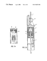
FIG. 3a is detailed cross-sectional view through another preferred form for a clasp from a third embodiment of a device for climbing according to the invention;
FIG. 3b is a side view of the entire clasp shown in FIG. 3a;
FIG. 3c is a top plan view of the clasp shown in FIGS. 3a and 3 b, showing the slotted sleeve for locking the clasp;
FIG. 4 is a side view of the entire device for climbing according to a preferred embodiment of the invention;
FIGS. 5a and 5 b are, respectively, a side view and a front view of another embodiment of the entire device for climbing according to the invention; and
FIGS. 6a and 6 b are, respectively, a side view and a front view of an additional embodiment of the entire device for climbing according to the invention, which has a harness for holding the user instead of a seat.
One form of a clasp for the climbing device, shown in FIG. 1, comprises a housing 21 with pivotable inclined bevels 2 mounted in it together with movable cotters 10 and rollers 11. In the housing 21 of FIG. 1 the inclined bevels 2 are arranged so that they can pivot on pivots 25 located in a top portion of the bevels. Elastomeric servo-components 9 press against the bottoms of the inclined bevels 2. Between the inclined bevels 2 and the cotter 10 there are rollers 11. At a prescribed height the rollers 11 press the cotters 10 against the rope 1 as a result of the geometric shape of the inclined bevels 2, whereby the time servo-component 9 is compressed. In this configuration the cotters 10 clamp onto the rope. The moving of the clasp is made possible by lifting the clasp by its housing 21 thereby releasing the rollers 11 and thus the cotters 10, which move back and disengage from the rope 1. The free movement of the device along the rope 1 is then possible until the time servo-components 9 have assumed their original form and again act to press the cotters 10 against the rope via the incline bevels 2 and rollers 11. Then the climbing process can start again.
Another form of the clasp 4,6 is shown in FIGS. 2a and 2 b. Parts that perform similar functions as in the embodiment of FIG. 1 are given the same reference numbers. The clasp 4,6 has housing 21. Instead of inclined bevels 2 it has a yoke 3 that is slidable in the housing 21. As in the embodiment of FIG. 1, cotters 10 engage and disengage from the rope 1. Rollers 11 are arranged between the cotters 10 and the yoke 3. The yoke 3 has an interior cavity that widens downward that has inner contours with beveled inclines. When the clasp clamps on the rope, the rollers 11 bear on the outer surfaces of the cotters 10 and the inner contours of the yoke 3 forcing the cotters 10 against the rope 1. A pulling element 15 is connected to the top of the yoke 3. A hydraulic or pneumatic cylinder bears on the bottom of the yoke 3 and acts as the time servo-component 9. A compressed spring 20 urges the yoke 3 downward into a clamping configuration.
The embodiments of the clasp 4,6 shown in FIGS. 3a, 3 b, and 3 c is the same as the embodiment of FIGS. 2a and 2 b, except that the pulling element 15 is formed slightly differently and that in the vicinity of the slotted sleeve 19, there is a central open slot 38 provided in the clasp. A rotatable slotted sleeve 19 is provided to lock the clasp.
The structure and operation of various embodiments of the entire climbing device according to the invention are now explained.
The embodiment of the device for climbing in FIG. 4 comprises a solid seat 7, frame handles 17 attached to opposite sides of the solid seat 7, respective upper clasps 4 (embodiment of FIG. 2b) attached to corresponding frame handles 17 near or at the solid seat 7, guide wheels 34 attached to upper parts of the frame handles 17, respective ropes 1 passing over the guide wheels and through the upper clasps 4, respective pedal levers 8, respective lower clasps 6 attached to the pedal levers 8 and through which the rope i also passes and compression springs 16 connecting the upper and lower clasps with each other. The frame handles 17 also have joints in the vicinity of the solid seat 7 and rotatable cams 18 are connected to the frame handles 17 between the pivots and the joints. The pedal levers 8 are connected to the pulling elements 16 for the upper clasps, whereby the upper clasps are operable by the pedal levers.
FIG. 4 shows a climbing device, which] could be used to rescue persons. The basis for the climbing motion is the moving characteristic of clasps 4 and 6. If a force acts downwards on clasps 4 and 6 (the clasp is burdened with the weight of the climbing person, for instance), the ropes 1, here the weight-bearing element, is then clamped in clasps 4 and/or 6. If one of the clasps, either 4 or 6, is relieved of the downward acting force, it can be moved along its rope 1.
The upward climb is therefore performed as follows.
The two lower clasps 6 are first clamped in the two ropes 1 by the downward weight of the climbing device and the person. By pressing the two pedal levers 8 downward the two upper clasps 4 are released, their time servo components 9 are activated, and they are moved upward together with the climbing device along rope 1. If then the pedal levers 8 are released and the weight is put on the solid seat 7, the upper clasps 4 clamp down on the rope as a result of the downward force.
If the pedal levers 8 are released, the recuperating spring 16 pulls the pedal levers 8 upward. This then releases the two lower clasps 6 and the restoring springs 16 move upward on ropes 1. The time servo-components 9 in the lower clasps 6 are activated with each release.
If the pedal levers 8 have returned to their initial position, the lower clasps 6 again clamp on the ropes 1 after the delay for reaction of the time servo-component 9 is concluded. The entire cycle can commence once again.
Descent is performed as follows.
The time servo-component 9 of the invention is also decisive for descent. In this example they function as shock absorbers in clasps 4 and 6. If the weight is released from clasps 4 and 6, they only re-clamp on ropes 1 after a short delay. During this short delay the climbing device and the user descend. The pedal levers 8 are briefly released and then pressed downward. Within the above-mentioned short delay the lower clasps 6 move downward with the pedal levers 8 along ropes 1 and then clamp down on ropes 1. Thereafter the upper clasps 4 are briefly released. Within the short period of time caused by the delay from the time servo-component the upper clasps 4 and therefore the seat 7 as well can move downward.
The clamping grip on the rope can be released by the upward movement of the clasp, which relieves downward force on the clasp. As in the embodiments shown In FIGS. 2a and 2 b and 3 a and 3 b, a short lifting of the yoke 3, e.g. by pulling element 15, is sufficient to release the pressure between the parts of the clasp. Needle cages for the rollers 11 and cotters 10 fall downward through their own weight in the component and the clasp is open.
The embodiments of FIG. 5 and 6 have a movable seat 12 or merely a harness 23 and are designed for fast climbing.
In the embodiment of FIG. 5a and 5 b connecting means for holding the climber includes system belts 13 and a movable seat 12, which is attached to the two upper clasps 4 engaged on two ropes 1 by the system belts 13, so that a connection between the movable seat and the upper clasps is pressure-stable in a longitudinal direction of the system belts 13. The system belts are preferably form-locked in the upper clasps so that the system belts cannot slip out of the upper clasps. In these preferred embodiments tension springs 16 are arranged between the movable seat 12 and the lower clasps and additional tension springs 16 are arranged between the movable seat 12 and the upper clasps. The ropes 1 pass through the tension springs 16. There are no supporting handle frames as in the previous embodiment of FIG. 4.
Slits have been made in the housings of the upper clasps 4 in which form-locking connecting elements are hooked to which the system belts 13 are attached. The safety ropes 14 are hooked in the above-mentioned connecting elements, whereby an unintentional release of the above-mentioned connecting elements from the clasps 4 can be hindered.
The seat 12 is provided with seatbelt 24, which is attached to the lower ends of the system belts 13. The tension springs 16 are attached with their outer ends to the clasps 4 and 6 and with the inside ends to the seat 12. The rod 5 with the foot holders 36 is hung, form-locked, in the lower clasps 6.
A stay-bar, which is not shown, assures the required distance for climbing, for instance to the building.
The climbing person straps on the harness 23 and hooks the safety ropes 14 in the above-mentioned connecting elements. In this way the person is protected from a fall. The seatbelt 24 is then closed and the feet inserted in the foot holders 36 of the rod 5.
The force goes from the seat 12 through the system belts 13 and the dosed upper clasps 4 to the ropes 1.
When climbing the lower clasps 6 are moved upwards by means of the rod 5 with the aid of the lower tension springs 16 after briefly weighting them. In this position the time servo-components 9 gives the impulse to close the lower clasps 6.
The climber can then shift their weight to the rod 5, stand up and push the upper clasps 4 upwards against the pull of the upper tension springs 16. Then the climber can sit down again and repeat the procedure again.
When descending the lower clasps 6 are pushed downwards until the legs are almost completely extended, as described above, after a short weighting and unweighting.
After clamping the lower clasps 6, the climber stands up and unweights the upper clasps 4 with their hands—thus releasing them—and then moves the clasps to shoulder height. After automatically clamping of the upper clasps 4 by means of the time servo-components 9, the climber sits and the procedure can be repeated again.
If the connection between the seat 12 and upper clasps 4 in the system belts is pressure-stable, the clasps 4 will, as described above, be pushed upwards without the use of the hands when the climber stands up.
Instead of the rod 5 it is possible to attach the clasps 6 directly to the shoes of the climber in a suitable manner, thus allowing an alternative climbing.
The embodiment shown in FIGS. 6a and 6 b is similar to the embodiment shown in FIGS. 5a and 5 b. Instead of the movable seat 12, only a harness 23 is provided, which is connected with the upper clasps 4 by means of safety lines 14. Also only a single spring 16 connects the upper clasp 4 on one rope to its associated lower clasp 6 and the rope runs through It. This embodiment also has two ropes.
The lower clasps are connected with each other with swiveling rod 5 that accommodates the foot holders 36, as in the previous embodiment.
In this variation a harness is to be selected that has shoulder rings and allows sitting. To stabilize the climber the safety rope 14 is attached to the back ring of the harness 23 and led through the shoulder rings of the harness.
The climbing device has the advantage of being able to be employed in many different ways.
It is useful for leisure-time activity and sports as well as for rescue and salvage operation whether in the mountains or for the fire department
The climbing device is particularly advantageous for repair work, cleaning and other work on facades and buildings.
Claims (11)
1. A device for climbing at least one weight-bearing element (1), said device comprising
releasable clasps (4, 6) each comprising a housing having a top wall and side walls and means for clamping said at least one weight-bearing element (1) in response to a downward force acting thereon and means for releasing said at least one weight-bearing element (1) when said downward force is relieved; and
connecting means (7, 8; 17) attached to said clasps (4,6) for holding a climber so that said climber is able to apply and relieve said downward force by shifting weight of said climber;
wherein each of said clasps comprises a time servo-component (9) acting on said means for clamping said at least one weight-bearing element to again clamp said at least one weight-bearing element (1) when a predetermined time interval starting from relief of said downward pressure expires;
wherein said time servo-component (9) is an elastic rubber member, a compression spring (20), a hydraulic spring or a pneumatic spring; and
wherein said means for clamping comprise a yoke (3) and cotters (10) arranged in an interior space in said yoke on opposite sides of said at least one weight-bearing element (1), said yoke responding to said time servo-component (9) when said time servo-component acts on said means for clamping to engage the cotters (10) with said at least one weight-bearing element (1); and said means for releasing said at least one weight-bearing element comprises a vertical extending rod (15) connected to the yoke (3) mounted in said housing and extending upwardly through said top wall for manually lifting the yoke (3) to relieve the cotters (10) so that said cotters (10) do not bear on said at least one weight-bearing element (15).
2. The device as defined in claim 1 , wherein said clasps (4,6) for said at least one weight-bearing element (1) comprise at least one upper clasp (4) and at least one lower clasp (6) and said at least one lower clasp (6) is arranged on said at least one weight-bearing element below said at least one upper clasp (4).
3. The device as defined in claim 2 , wherein said connecting means includes a solid seat (7) and said at least one upper clasp (4) is located at said solid seat (7).
4. The device as defined in claim 2 , wherein said connecting means includes a system belt (13) and a movable seat (12), said movable seat (12) being attached to said at least one upper clasp (4) by means of said system belt (13), so that a connection between said movable seat and said at least one upper clasp (4) is pressure-stable in a longitudinal direction of said system belt.
5. The device as defined in claim 4 , wherein said system belt (13) is form-locked in said at least one upper clasp (4), so that said system belt cannot slip out of said at least one upper clasp.
6. The device as defined in claim 4 , further comprising at least one tension spring (16) arranged between said movable seat (12) and said at least one lower clasp (6) and at least one other tension spring (16) arranged between said movable seat (12) and said at least one upper clasp (4), and wherein said at least one weight-bearing element (1) passes through said at least one tension spring (16) and said at least one other tension spring (16).
7. The device as defined in claim 6 , wherein said at least one weight-bearing element (1) consists of two ropes, and respective ones of said two ropes have corresponding ones of said at least one lower clasp and said at least one upper clasp engaged therewith and are attached to said movable seat (12).
8. The device as defined in claim 3 wherein said at least one weight-bearing element (1) consists of two ropes, respective ones of said two ropes have corresponding ones of said at least one lower clasp and said at least one upper clasp engaged therewith; and further comprising frame handles (17) attached to opposite sides of said solid seat (7), said frame handles having respective joints, pedal levers (8) for feet of said climber pivotally connected to said frame handles at respective pivots and rotating cams (18) connected to said frame handles (17) between said respective pivots and said respective joints.
9. The device as defined in claim 8 , further comprising guide wheels (34) attached to said frame handles (17) over which said ropes are guided and tensions springs (16) arranged between the at least one upper clasp (4) and the at least one lower clasp (6) through which said ropes pass to said feet of the climber.
10. The device as defined in claim 2 , wherein each of through said clasps (4,6) comprises a housing; said yoke (3) is mounted in through said housing provided with an interior space having inner contours with beveled inclines widening downward in said inner space; said cotters (10) are positioned on opposite sides of said at least one weight-bearing element (1) in said inner space; and each of said clasps includes rollers (11) arranged movably, but securably, between said cotters (10) and said inner contours of said yoke (3); and said time servo-component (9) is arranged at or bearing on a bottom of said yoke.
11. The device as defined in claim 10 , wherein the connection means comprises a movable seat (12), at least one system belt (13) attaching the movable seat (12) and the housing (21) of the at least one upper clasp (4), at least one safety line (14) attaching the movable seat (12) to the housing (21) of the at least one upper clasp (4), tension springs (16) connected between the movable seat (12) and the at least one lower clasp (6), at least one grip (22) attached to the at least one upper clasp (4) and a swiveling rod (5) on which foot holders (36) are mounted, said swiveling rod (5) being attached to the at least one lower clasp (6).
Priority Applications (1)
| Application Number | Priority Date | Filing Date | Title |
|---|---|---|---|
| US10/775,439 US7073628B2 (en) | 1999-02-03 | 2004-02-10 | Device for climbing on extended supporting elements, such as ropes, with releasable automatically reclamping clasps |
Applications Claiming Priority (3)
| Application Number | Priority Date | Filing Date | Title |
|---|---|---|---|
| DE19905257A DE19905257A1 (en) | 1999-02-03 | 1999-02-03 | Climbing device |
| DE19905257 | 1999-02-03 | ||
| PCT/DE1999/000956 WO2000045898A1 (en) | 1999-02-03 | 1999-03-25 | Device for climbing |
Related Parent Applications (1)
| Application Number | Title | Priority Date | Filing Date |
|---|---|---|---|
| PCT/DE1999/000956 A-371-Of-International WO2000045898A1 (en) | 1999-02-03 | 1999-03-25 | Device for climbing |
Related Child Applications (1)
| Application Number | Title | Priority Date | Filing Date |
|---|---|---|---|
| US10/775,439 Continuation US7073628B2 (en) | 1999-02-03 | 2004-02-10 | Device for climbing on extended supporting elements, such as ropes, with releasable automatically reclamping clasps |
Publications (1)
| Publication Number | Publication Date |
|---|---|
| US6782973B1 true US6782973B1 (en) | 2004-08-31 |
Family
ID=7896890
Family Applications (2)
| Application Number | Title | Priority Date | Filing Date |
|---|---|---|---|
| US09/890,495 Expired - Fee Related US6782973B1 (en) | 1999-02-03 | 1999-03-25 | Device for climbing on extended support elements, such as ropes, with releasable automatically reclamping clasps |
| US10/775,439 Expired - Fee Related US7073628B2 (en) | 1999-02-03 | 2004-02-10 | Device for climbing on extended supporting elements, such as ropes, with releasable automatically reclamping clasps |
Family Applications After (1)
| Application Number | Title | Priority Date | Filing Date |
|---|---|---|---|
| US10/775,439 Expired - Fee Related US7073628B2 (en) | 1999-02-03 | 2004-02-10 | Device for climbing on extended supporting elements, such as ropes, with releasable automatically reclamping clasps |
Country Status (7)
| Country | Link |
|---|---|
| US (2) | US6782973B1 (en) |
| EP (1) | EP1148913B1 (en) |
| JP (1) | JP4308442B2 (en) |
| AT (1) | ATE329661T1 (en) |
| AU (1) | AU4131799A (en) |
| DE (3) | DE19905257A1 (en) |
| WO (1) | WO2000045898A1 (en) |
Cited By (5)
| Publication number | Priority date | Publication date | Assignee | Title |
|---|---|---|---|---|
| US20060273293A1 (en) * | 2005-04-20 | 2006-12-07 | Atlas Devices Llc | Powered rope ascender and portable rope pulling device |
| US20070194290A1 (en) * | 2005-04-20 | 2007-08-23 | Atlas Devices Llc | Device to enable rope pulling functionality using a rotational power source |
| US20080128668A1 (en) * | 2006-11-14 | 2008-06-05 | Atlas Devices Llc | Multiple line powered rope ascender and portable hoist |
| US20080203370A1 (en) * | 2005-04-20 | 2008-08-28 | Atlas Devices, Llc | Powered Rope Ascender and Portable Rope Pulling Device |
| CN111659085A (en) * | 2020-05-29 | 2020-09-15 | 周哉明 | Electric power engineering is with climbing instrument that has automatic clamping function portable |
Families Citing this family (9)
| Publication number | Priority date | Publication date | Assignee | Title |
|---|---|---|---|---|
| EP2173506B1 (en) | 2007-07-16 | 2011-05-18 | Stopinc Aktiengesellschaft | Sliding closure for a vessel containing molten metal |
| US8511433B2 (en) * | 2010-07-12 | 2013-08-20 | Brent Place | Tree stand hoist system |
| WO2013143513A1 (en) | 2012-03-30 | 2013-10-03 | LU, Ai Gen | Device for climbing |
| CN102684083B (en) * | 2012-04-21 | 2014-12-10 | 国家电网公司 | Convenient-to-use high-altitude structure walkabout for hanging double rope |
| FR3012742A1 (en) * | 2013-11-04 | 2015-05-08 | Georges Rene Henri Boissier | DYNAMIC BRAKING SELF-INSULATING SYSTEM ATTACHED TO THE FOOT OF THE ESCALADER WAY |
| CN108837999B (en) * | 2018-08-28 | 2023-10-10 | 国网山东省电力公司电力科学研究院 | Power transmission tower body maintenance device |
| DE102020007719A1 (en) | 2020-12-17 | 2022-06-23 | Sigmar Ulrich Burger | Arrangement for climbing |
| CN113882275B (en) * | 2021-11-15 | 2022-05-17 | 孙海霞 | Support bracket is used in public road bridge roof beam construction |
| CN115888039A (en) * | 2022-11-20 | 2023-04-04 | 贵州电网有限责任公司 | Passive ectoskeleton climbers of stepping on pole |
Citations (8)
| Publication number | Priority date | Publication date | Assignee | Title |
|---|---|---|---|---|
| US1114832A (en) * | 1913-11-22 | 1914-10-27 | Egbert Whitney | Hoisting-machine. |
| US1754132A (en) * | 1928-11-14 | 1930-04-08 | Harry Van Raaphorst | Scaffold jack |
| US3335469A (en) * | 1963-11-19 | 1967-08-15 | Barrow Hepburn & Gale Ltd | Personal safety equipment |
| US4921069A (en) | 1989-03-28 | 1990-05-01 | Boyles Ralph D | Climbing device |
| US5131491A (en) | 1990-07-18 | 1992-07-21 | Frost Engineering Development Corp. | Descent controller |
| US5577576A (en) | 1994-06-23 | 1996-11-26 | Zedel | Disengageable descender with self-locking of the rope |
| DE19643455A1 (en) | 1996-10-10 | 1998-04-16 | Schmidt Gmbh Arbeits Und Umwel | Rope climbing device for vertical climbing |
| DE19726035A1 (en) | 1997-06-19 | 1998-12-24 | Schmidt Gmbh | Climbing equipment operated by body power |
Family Cites Families (4)
| Publication number | Priority date | Publication date | Assignee | Title |
|---|---|---|---|---|
| US1117800A (en) * | 1912-10-08 | 1914-11-17 | James R Davidson | Hoisting device. |
| US1964995A (en) * | 1931-01-02 | 1934-07-03 | Fischer & Hayes Rope And Steel | Scaffold jack |
| US3677367A (en) * | 1971-06-14 | 1972-07-18 | Albert Shotmeyer | Manually operable elevator |
| US3926278A (en) * | 1974-01-08 | 1975-12-16 | Albert E Molnar | Emergency escape sling |
-
1999
- 1999-02-03 DE DE19905257A patent/DE19905257A1/en not_active Withdrawn
- 1999-03-25 EP EP99924723A patent/EP1148913B1/en not_active Expired - Lifetime
- 1999-03-25 DE DE19983008T patent/DE19983008D2/en not_active Expired - Fee Related
- 1999-03-25 JP JP2000597017A patent/JP4308442B2/en not_active Expired - Fee Related
- 1999-03-25 DE DE59913564T patent/DE59913564D1/en not_active Expired - Lifetime
- 1999-03-25 AT AT99924723T patent/ATE329661T1/en not_active IP Right Cessation
- 1999-03-25 US US09/890,495 patent/US6782973B1/en not_active Expired - Fee Related
- 1999-03-25 AU AU41317/99A patent/AU4131799A/en not_active Abandoned
- 1999-03-25 WO PCT/DE1999/000956 patent/WO2000045898A1/en active IP Right Grant
-
2004
- 2004-02-10 US US10/775,439 patent/US7073628B2/en not_active Expired - Fee Related
Patent Citations (8)
| Publication number | Priority date | Publication date | Assignee | Title |
|---|---|---|---|---|
| US1114832A (en) * | 1913-11-22 | 1914-10-27 | Egbert Whitney | Hoisting-machine. |
| US1754132A (en) * | 1928-11-14 | 1930-04-08 | Harry Van Raaphorst | Scaffold jack |
| US3335469A (en) * | 1963-11-19 | 1967-08-15 | Barrow Hepburn & Gale Ltd | Personal safety equipment |
| US4921069A (en) | 1989-03-28 | 1990-05-01 | Boyles Ralph D | Climbing device |
| US5131491A (en) | 1990-07-18 | 1992-07-21 | Frost Engineering Development Corp. | Descent controller |
| US5577576A (en) | 1994-06-23 | 1996-11-26 | Zedel | Disengageable descender with self-locking of the rope |
| DE19643455A1 (en) | 1996-10-10 | 1998-04-16 | Schmidt Gmbh Arbeits Und Umwel | Rope climbing device for vertical climbing |
| DE19726035A1 (en) | 1997-06-19 | 1998-12-24 | Schmidt Gmbh | Climbing equipment operated by body power |
Cited By (10)
| Publication number | Priority date | Publication date | Assignee | Title |
|---|---|---|---|---|
| US20060273293A1 (en) * | 2005-04-20 | 2006-12-07 | Atlas Devices Llc | Powered rope ascender and portable rope pulling device |
| US20070194290A1 (en) * | 2005-04-20 | 2007-08-23 | Atlas Devices Llc | Device to enable rope pulling functionality using a rotational power source |
| US7261278B2 (en) | 2005-04-20 | 2007-08-28 | Atlas Devices, Llc | Powered rope ascender and portable rope pulling device |
| US20080017838A1 (en) * | 2005-04-20 | 2008-01-24 | Atlas Devices, Llc | Powered rope ascender and portable rope pulling device |
| US20080203370A1 (en) * | 2005-04-20 | 2008-08-28 | Atlas Devices, Llc | Powered Rope Ascender and Portable Rope Pulling Device |
| US7581715B2 (en) | 2005-04-20 | 2009-09-01 | Atlas Devices, Llc | Powered rope ascender and portable rope pulling device |
| US7934698B2 (en) | 2005-04-20 | 2011-05-03 | Atlas Devices, Llc | Powered rope ascender and portable rope pulling device |
| US20080128668A1 (en) * | 2006-11-14 | 2008-06-05 | Atlas Devices Llc | Multiple line powered rope ascender and portable hoist |
| CN111659085A (en) * | 2020-05-29 | 2020-09-15 | 周哉明 | Electric power engineering is with climbing instrument that has automatic clamping function portable |
| CN111659085B (en) * | 2020-05-29 | 2021-07-20 | 周哉明 | Electric power engineering is with climbing instrument that has automatic clamping function portable |
Also Published As
| Publication number | Publication date |
|---|---|
| US7073628B2 (en) | 2006-07-11 |
| ATE329661T1 (en) | 2006-07-15 |
| AU4131799A (en) | 2000-08-25 |
| EP1148913B1 (en) | 2006-06-14 |
| US20040154866A1 (en) | 2004-08-12 |
| JP4308442B2 (en) | 2009-08-05 |
| WO2000045898A1 (en) | 2000-08-10 |
| DE59913564D1 (en) | 2006-07-27 |
| DE19983008D2 (en) | 2002-02-28 |
| JP2003526397A (en) | 2003-09-09 |
| DE19905257A1 (en) | 2000-08-10 |
| EP1148913A1 (en) | 2001-10-31 |
Similar Documents
| Publication | Publication Date | Title |
|---|---|---|
| US6782973B1 (en) | Device for climbing on extended support elements, such as ropes, with releasable automatically reclamping clasps | |
| US6776317B1 (en) | Tool lanyard for holding tools | |
| US5819772A (en) | Walker for disabled persons | |
| EP0553536A1 (en) | Gymnastic apparatus | |
| US20100066042A1 (en) | Knee Protector Dolly | |
| KR20150111346A (en) | Exercise apparatus having a slidable weight bar assembly | |
| JP2005312953A (en) | Auxiliary tool for transferring steel pipe member | |
| US3724593A (en) | Rope climbing device | |
| US4921069A (en) | Climbing device | |
| US3403750A (en) | Rescue device | |
| US6286625B1 (en) | Rope climbing device | |
| KR100540206B1 (en) | Descent apparatus of safety | |
| EP0047232B1 (en) | Anchoring device for mountain climbers | |
| CN214633809U (en) | Climbing pole safety suit | |
| CA2046608C (en) | Pump jack | |
| US3677367A (en) | Manually operable elevator | |
| WO2005094946A1 (en) | Foot operated ascenders | |
| KR200441323Y1 (en) | Fire escape apparatus | |
| US3765507A (en) | Fire escape device | |
| KR20100137716A (en) | Descending life line for emergency escape | |
| US3673615A (en) | Body attached stilts with vertically adjustable steps | |
| KR101968557B1 (en) | Safety equipment for working of external wall | |
| CN213724718U (en) | Combined type rapid ascender | |
| CN111514546A (en) | Manual pole-climbing assistor | |
| CN113384830B (en) | Tower crane emergency escape self-rescue knapsack type slow descending device and using method thereof |
Legal Events
| Date | Code | Title | Description |
|---|---|---|---|
| AS | Assignment |
Owner name: SCHMIDT INNOVATION, GERMANY Free format text: ASSIGNMENT OF ASSIGNORS INTEREST;ASSIGNOR:SCHMIDT, SIEGFRIED;REEL/FRAME:012155/0620 Effective date: 20010813 |
|
| REMI | Maintenance fee reminder mailed | ||
| LAPS | Lapse for failure to pay maintenance fees | ||
| STCH | Information on status: patent discontinuation |
Free format text: PATENT EXPIRED DUE TO NONPAYMENT OF MAINTENANCE FEES UNDER 37 CFR 1.362 |
|
| FP | Lapsed due to failure to pay maintenance fee |
Effective date: 20080831 |