US668317A - Miner's candlestick. - Google Patents
Miner's candlestick. Download PDFInfo
- Publication number
- US668317A US668317A US3611500A US1900036115A US668317A US 668317 A US668317 A US 668317A US 3611500 A US3611500 A US 3611500A US 1900036115 A US1900036115 A US 1900036115A US 668317 A US668317 A US 668317A
- Authority
- US
- United States
- Prior art keywords
- handle
- holder
- point
- hook
- pivoted
- Prior art date
- Legal status (The legal status is an assumption and is not a legal conclusion. Google has not performed a legal analysis and makes no representation as to the accuracy of the status listed.)
- Expired - Lifetime
Links
- 241000776270 Polytaenia texana Species 0.000 description 3
- 210000002105 tongue Anatomy 0.000 description 3
- 206010044625 Trichorrhexis Diseases 0.000 description 1
- 238000010276 construction Methods 0.000 description 1
Images
Classifications
-
- F—MECHANICAL ENGINEERING; LIGHTING; HEATING; WEAPONS; BLASTING
- F21—LIGHTING
- F21V—FUNCTIONAL FEATURES OR DETAILS OF LIGHTING DEVICES OR SYSTEMS THEREOF; STRUCTURAL COMBINATIONS OF LIGHTING DEVICES WITH OTHER ARTICLES, NOT OTHERWISE PROVIDED FOR
- F21V35/00—Candle holders
Definitions
- My invention relates to improvements in devices for holding candles in mining-shafts, tunnels, and like places.
- a handle having elastic extensions, a point and a hook pivoted and turnable in said handle, so as to be extended or folded up, and a thimble or holder for the candle, also turnable and adjustable with relation to the handle.
- These parts are formed with spring and locking adjustments, so as to remain in any position at which they are set.
- Figure 1 is a plan of my device in a foldedup position.
- Fig. 2 is an end view of the same.
- Fig. 3 is a part section and a longitudinal elevation showing the device in position for use.
- Fig. 4 is a section through the holder and a view of one end of the device.
- A is a curved loop or handle having the sides extended parallel with each other, as shown at 2.
- At one side of one of the arms 2 is an angular piece 3, and to this piece the circular holder 4 for the candle is pivoted.
- This holder has the pivoted arm split a short distance, so as to form an elastic central tongue 5, through which the holding-rivet passes.
- the spring of this tongue acts to press the outside portion 6 against which the holding-plate abuts, so that there will be friction enough to retain the holder at any angle to which it may be turned. It may be turned with its axis parallel or at right angles with the holder-shank.
- the holder also has an overlapping extension 7 at oneside projecting tangentially beyond the periphery.
- the point or stab as it is technically called, is shown at 8 and is pivoted between the sides 2, as at 9.
- the inner end projecting beyond the pivot is split, as shown, so that the two sides have a tendency to separate, and being slightly wider than the space between the arms 2 the inner ends of the point will be compressed between these sides when turned so that the point stands in line with the extensions.
- Raised lugs 10 are formed on one or both of the split ends of the point, and these engage with corresponding notches or depressions 11, formed in the inner faces of the sides 2, so that when in this position the point is firmly locked; buta little pressure will release it and allow it to be turned so as to fold back into the handle.
- the hook 12 is the hook, which serves to hang the apparatus when it is not convenient to support it by the point.
- This hook is pivoted between the parts 2 and has the ends also split and made elastic, so as to spread and produce a friction between themselves and the inner faces of parts 2.
- One of these faces is formed with notches, as at 13, so that when the hook is in its vertical or hanging position the elastic ends will engage with a notch, and thus retain it in position.
- the edges of the split portion of the hook may also have lugs, as at 15, and the rear end of the split portion of the point has corresponding notches 16, which engage when the point is in line with the parts 2 and when the hook is in its vertical position, thus forming an additional look.
Landscapes
- Engineering & Computer Science (AREA)
- General Engineering & Computer Science (AREA)
- Arrangement Of Elements, Cooling, Sealing, Or The Like Of Lighting Devices (AREA)
Description
No. 668,3!7. Patented Feb. l9, I90l.
G. T. PARSLEY.
MINERS CANDLESTICK.
(Application filed mv. 10, 1900.
(No Model.)
Nine STATES GEORGE T. PARSLEY, OF HORNBROOK, CALIFORNIA, ASSIGNOR OF ONE- HALF TO J. W. DOWNING, OF SAME PLACE.
MINERS CANDLESTICK.
SPECIFICATION forming part of Letters Patent No. 668,317, dated February 19, 1901.
Application filed November 10, 1900. $erial No. 36,115. (No model.)
To all whom it may concern.-
Be it known that I, GEORGE T. PARSLEY, a citizen of the United States, residing at Hornbrook, county of Siskiyou,State of California, have invented an Improvement in Miners Candlesticks; and I hereby declare the following to be a full, clear, and exact description of the same.
My invention relates to improvements in devices for holding candles in mining-shafts, tunnels, and like places.
It consists of a handle having elastic extensions, a point and a hook pivoted and turnable in said handle, so as to be extended or folded up, and a thimble or holder for the candle, also turnable and adjustable with relation to the handle. These parts are formed with spring and locking adjustments, so as to remain in any position at which they are set.
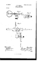
The invention also comprises details of construction, as set forth in the accompanying drawings, in which Figure 1 is a plan of my device in a foldedup position. Fig. 2 is an end view of the same. Fig. 3 is a part section and a longitudinal elevation showing the device in position for use. Fig. 4 is a section through the holder and a view of one end of the device.
As shown in the drawings, A is a curved loop or handle having the sides extended parallel with each other, as shown at 2. At one side of one of the arms 2 is an angular piece 3, and to this piece the circular holder 4 for the candle is pivoted. This holder has the pivoted arm split a short distance, so as to form an elastic central tongue 5, through which the holding-rivet passes. The spring of this tongue acts to press the outside portion 6 against which the holding-plate abuts, so that there will be friction enough to retain the holder at any angle to which it may be turned. It may be turned with its axis parallel or at right angles with the holder-shank. The holder also has an overlapping extension 7 at oneside projecting tangentially beyond the periphery.
The point or stab, as it is technically called, is shown at 8 and is pivoted between the sides 2, as at 9. The inner end projecting beyond the pivot is split, as shown, so that the two sides have a tendency to separate, and being slightly wider than the space between the arms 2 the inner ends of the point will be compressed between these sides when turned so that the point stands in line with the extensions. Raised lugs 10 are formed on one or both of the split ends of the point, and these engage with corresponding notches or depressions 11, formed in the inner faces of the sides 2, so that when in this position the point is firmly locked; buta little pressure will release it and allow it to be turned so as to fold back into the handle.
12 is the hook, which serves to hang the apparatus when it is not convenient to support it by the point. This hook is pivoted between the parts 2 and has the ends also split and made elastic, so as to spread and produce a friction between themselves and the inner faces of parts 2. One of these faces is formed with notches, as at 13, so that when the hook is in its vertical or hanging position the elastic ends will engage with a notch, and thus retain it in position. The edges of the split portion of the hook may also have lugs, as at 15, and the rear end of the split portion of the point has corresponding notches 16, which engage when the point is in line with the parts 2 and when the hook is in its vertical position, thus forming an additional look.
When not in use, the hook and point are folded back into the curved loop or handle.
Having thus described my invention, what I claim as new, and desire to secure by Letters Patent, is-
1. The combination in a miners candlestick of the handle having the parallel separated extensions, the holding-point pivoted between said extensions having the rear end split and made elastic, and locking-lugs by which it is engaged and held in place and in line for use.
2. The combination in a miners candlestick of the handle, the parallel extensions, the hanging-hook having its inner end split and pivoted therethrough between the extensions and notches with which the elastic separated ends engage to retain the hook in position.
3. The combination in a miners candlestick of a handle having parallel extensions, a pointed holder pivoted between said extensions, having the rear end separated and forming elastic arms, locking-notches formed in said arms, a hook having the inner ends split and pivoted between the sides of the handle and turnable so as to lie against the rear end of the pointed holder, said hooks having lugs to engage the'notches of said holder.
4. The combination in a miners candlestick of a handle having parallel sides, a locking-point and hanging-hook with split inner ends pivoted between the sides of the handle, and means for interlocking them therewith, and a cylindrical holder for the candle, an arm projecting from the handle sides to which said holder is pivoted, elastic tongues formed upon the holder through Whichthe pivoting-rivet passes.
5. The combination in a miners candle- GEORGE T. PARSLEY.
Witnesses:
D. C. EARHART, J. L. OoYLE.
Priority Applications (1)
| Application Number | Priority Date | Filing Date | Title |
|---|---|---|---|
| US3611500A US668317A (en) | 1900-11-10 | 1900-11-10 | Miner's candlestick. |
Applications Claiming Priority (1)
| Application Number | Priority Date | Filing Date | Title |
|---|---|---|---|
| US3611500A US668317A (en) | 1900-11-10 | 1900-11-10 | Miner's candlestick. |
Publications (1)
| Publication Number | Publication Date |
|---|---|
| US668317A true US668317A (en) | 1901-02-19 |
Family
ID=2736872
Family Applications (1)
| Application Number | Title | Priority Date | Filing Date |
|---|---|---|---|
| US3611500A Expired - Lifetime US668317A (en) | 1900-11-10 | 1900-11-10 | Miner's candlestick. |
Country Status (1)
| Country | Link |
|---|---|
| US (1) | US668317A (en) |
-
1900
- 1900-11-10 US US3611500A patent/US668317A/en not_active Expired - Lifetime
Similar Documents
| Publication | Publication Date | Title |
|---|---|---|
| US668317A (en) | Miner's candlestick. | |
| US1127987A (en) | Fishing-pole hanger. | |
| US721615A (en) | Tobacco-leaf hanger. | |
| US682602A (en) | Reflector. | |
| US295519A (en) | John p | |
| US200082A (en) | Improvement in lamp-brackets | |
| US1083092A (en) | Harness-hanger. | |
| US484695A (en) | Lamp-shade support | |
| US354261A (en) | hekry smith | |
| US554808A (en) | Half to emmett gilbreath | |
| US996717A (en) | Adjustable support for smoke-shells. | |
| US1220987A (en) | Chimney and stovepipe attachment. | |
| US1069170A (en) | Folding candlestick. | |
| US285310A (en) | shaffer | |
| US566193A (en) | Extension electric-lamp holder | |
| US1026622A (en) | Miner's lamp. | |
| US1058282A (en) | Lamp-chimney holder. | |
| US622121A (en) | Stovepipe-holder | |
| US312810A (en) | Charles p | |
| US602281A (en) | Testing-cap and clamp | |
| US1476380A (en) | Fastener | |
| US1094977A (en) | Supporting-bracket. | |
| US498780A (en) | Robert franken | |
| US740326A (en) | Cable-hanger. | |
| US1212406A (en) | Lamp-holder. |