US6653753B1 - Linear motor - Google Patents
Linear motor Download PDFInfo
- Publication number
- US6653753B1 US6653753B1 US09/719,663 US71966301A US6653753B1 US 6653753 B1 US6653753 B1 US 6653753B1 US 71966301 A US71966301 A US 71966301A US 6653753 B1 US6653753 B1 US 6653753B1
- Authority
- US
- United States
- Prior art keywords
- yoke
- vibrator
- inner yoke
- linear motor
- magnetic
- Prior art date
- Legal status (The legal status is an assumption and is not a legal conclusion. Google has not performed a legal analysis and makes no representation as to the accuracy of the status listed.)
- Expired - Fee Related
Links
Images


Classifications
-
- H—ELECTRICITY
- H02—GENERATION; CONVERSION OR DISTRIBUTION OF ELECTRIC POWER
- H02K—DYNAMO-ELECTRIC MACHINES
- H02K33/00—Motors with reciprocating, oscillating or vibrating magnet, armature or coil system
- H02K33/16—Motors with reciprocating, oscillating or vibrating magnet, armature or coil system with polarised armatures moving in alternate directions by reversal or energisation of a single coil system
Definitions
- the present invention relates to a linear motor performing linear motion.
- FIG. 19 illustrates a conventional linear motor.
- Tubular outer yoke 201 houses tubular inner yoke 203 having coil 202 .
- Permanent magnet 204 is disposed between outer yoke 201 and inner yoke 203 .
- Magnet 204 vibrates following the magnetic flux generated by inner yoke 203 , so that a vibrator—fixing magnet 204 —reciprocates.
- the permanent magnet is fixed to the vibrator on its outer yoke side.
- the vibrator is thus positioned between the inner yoke having the coil and the permanent magnet.
- a space between the inner yoke and the magnet becomes too wide.
- magnetic-flux-path incurs some loss.
- the magnetic flux generated by the inner yoke changes greatly, so that eddy current is produced at a vibrator facing the inner yoke.
- the vibrator supporting the permanent magnet is non-magnetic body, thus when the vibrator is placed between the magnet and the yoke, non-magnetic-section other than the space is produced.
- This structure allows the non-magnetic-section to interfere with magnetic-flux for generating vibration, thus the vibrator cannot vibrate efficiently.
- Both the inner and outer yokes are formed by laminating electromagnetic steel in the circumferential direction, therefore, manufacturing them is a cumbersome work.
- the objective of the present invention is to provide a linear motor, where a space between the permanent magnet and the inner yoke is provided as narrow as possible, the production of eddy current is thus restrained, and the yoke is easy to manufacture.
- the linear motor of the present invention comprises the following elements:
- the magnetic-flux-loops produced by the outer and inner yokes travel through the vibrator without being hindered by the vibrator. As a result, the linear motor can vibrate efficiently.
- the permanent magnet is fixed to the vibrator on its coil side, so that the magnet is placed closer to the yoke on the coil side.
- the linear motor of the present invention includes a plurality of coils in the inner yoke or outer yoke, and a plurality of permanent magnets on the side opposite to the coils of the vibrator.
- the plurality of permanent magnets arranged in the vibrator's vibrating direction have unlike polarities adjacently.
- the vibrator has slits between adjacent magnets, so that leakage flux produced between unlike adjacent polarities can be prevented.
- the electrical resistance of the vibrator of the present invention is not less than 100 ⁇ .cm, the production of eddy current can be restrained.
- the permeability of the vibrator of the present invention is preferably more than ten times of vacuum permeability.
- the vibrator is preferably made of the material mainly comprising iron and chrome.
- the vibrator is preferably made of the material including 80-90 wt % of iron and 10-20 wt % of chrome.
- the vibrator is preferably made of the material mainly comprising iron, chrome and aluminum.
- the vibrator is preferably made of the material including 75-88 wt % of iron, 10-20 wt % of chrome and 2-5 wt % of aluminum.
- the vibrator is preferably made of the material mainly comprising iron and silicon.
- the vibrator is preferably made of the material mainly comprising nickel and iron.
- At least one slit is provided on a side of the vibrator, so that the production of eddy current is restrained.
- This slit may be long and narrow in the vibrator's vibrating direction.
- At least one electrically insulated section made of resin is provided on a side of the vibrator, so that the production of eddy current is restrained.
- a compressor of the present invention comprises the following elements:
- a linear motor including:
- a coil provided to the outer yoke or the inner yoke
- a vibrator supporting the permanent magnet and made of magnetic material.
- the compressor can be driven efficiently.
- the linear motor of the present invention comprises the following elements:
- the permanent magnet is fixed to the outer yoke or inner yoke whichever includes the coil. This structure allows the permanent magnet to be placed closer to the yoke having the coil.
- the compressor of the present invention comprises the following elements:
- a linear motor including:
- a coil provided to the outer yoke or the inner yoke
- the permanent magnet is fixed to the outer yoke or inner yoke whichever includes the coil. This structure allows the compressor to be driven efficiently.
- the linear motor of the present invention comprises the following elements:
- This structure allows the linear motor to be manufactured with ease.
- the linear motor of the present invention may comprise the following elements:
- At least one of the outer yoke or inner yoke may be formed by compression-formed body made of metal magnetic particles.
- the yoke of the compressed and molded body of the present invention may be made of metal magnetic particles and electrically insulated resin.
- the yoke of the linear motor of the present invention may be a compression-formed body made of metal magnetic particles having an insulated layer on its surface.
- the yoke of the linear motor of the present invention is formed by metal magnetic particles and its surface electrically insulated may be made of inorganic material.
- the yoke of the linear motor of the present invention is divided in the cirumferential direction, so that the production of eddy current is restrained.
- the yoke of the linear motor of the present invention is divided in the circumferential direction and an insulating layer is provided to the bonding face of the yoke. This structure allows the motor to further restrain the production of eddy current.
- the compressor of the present invention comprises a linear motor including a yoke formed of a compression-formed body made of metal magnetic particles and a mover moving along the yoke.
- the linear motor of the present invention comprises the following elements:
- At least one of the outer yoke or inner yoke is formed by arranging a plurality of laminated blocks in an annular shape, and a space between the adjacent blocks is formed by the compression-formed body.
- the compressor of the present invention comprises the following elements:
- a linear motor including:
- At least one of the outer yoke or inner yoke is formed by arranging a plurality of laminated blocks in an annular shape, and a space between the adjacent blocks is formed by the compression-formed body.
- FIG. 1 ( a ) and FIG. 1 ( b ) are a cross section and a plan view of a linear motor in accordance with a first exemplary embodiment.
- FIG. 2 ( a ) is a partial cross section of the linear motor in accordance with the first embodiment
- FIG. 2 ( b ) is a partial cross section of a conventional linear motor.
- FIG. 3 ( a ) and FIG. 3 ( b ) are a cross section and a plan view of a linear motor in accordance with a second exemplary embodiment.
- FIG. 4 ( a ) and FIG. 4 ( b ) are a cross section and a plan view of a linear motor in accordance with a third exemplary embodiment.
- FIG. 5 is a cross section of another linear motor in accordance with the third embodiment.
- FIG. 6 ( a ) and FIG. 6 ( b ) are a cross section and a plan view of a linear motor in accordance with a fourth exemplary embodiment.
- FIG. 7 ( a ) and FIG. 7 ( b ) are a cross section and a plan view of a vibrator in accordance with a fourth exemplary embodiment.
- FIG. 8 is a cross section of a linear motor in accordance with a fifth exemplary embodiment.
- FIG. 9 is a cross section of a vibrator in accordance with the fifth embodiment.
- FIG. 10 is a cross section of another vibrator in accordance with the fifth embodiment.
- FIG. 11 is a cross section of still another vibrator in accordance with the fifth embodiment.
- FIG. 12 is a cross section of still further another vibrator in accordance with the fifth embodiment.
- FIG. 13 ( a ) and FIG. 13 ( b ) are a cross section and a plan view of a linear motor in accordance with a sixth exemplary embodiment.
- FIG. 14 is a flowchart illustrating a manufacturing process of a compressed and molded body in accordance with the sixth embodiment.
- FIG. 15 is a flowchart illustrating a manufacturing process of a compression-formed body in accordance with the sixth embodiment.
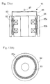
- FIG. 16 ( a ) and FIG. 16 ( b ) are a cross section and a plan view of a linear motor in accordance with a seventh exemplary embodiment.
- FIG. 17 ( a ) and FIG. 17 ( b ) are a cross section and a plan view of a linear motor in accordance with an eighth exemplary embodiment.
- FIG. 18 is a cross section of a linear motor compressor.
- FIG. 19 is a cross section of a conventional linear motor.
- FIG. 1 shows a construction of a linear motor.
- Linear motor 1 comprises the following elements:
- tubular vibrator 6 supporting magnets 5 a , 5 b.
- Magnets 5 a , 5 b are fixed to a side face of vibrator 6 on the side of inner yoke 4 .
- Output section 7 for supplying the vibration of vibrator 6 to outside, is disposed at an end of vibrator 6 .
- Output section 7 shapes in a lid closing tubular vibrator 6 .
- a resonance spring is disposed on an output shaft of output section 7 . Utilizing the resonance of the spring saves some force necessary for vibration, and also saves some driving current running through coils 2 .
- Inner yoke 3 is formed by laminating magnetic and rectangular steel sheets having two recesses in circumferential direction, and forms a tubular shape. Successive recesses form ring-shaped grooves on the outer wall of inner yoke 3 . Windings wound on these ring-shaped grooves form coils 2 .
- Outer yoke 4 is formed by laminating magnetic and rectangular sheets in circumferential direction, and forms a tubular shape.
- Inner yoke 3 is disposed in outer yoke 4 .
- the inner wall of outer yoke 4 is parallel to the outer wall of inner yoke 3 , and there is an even clearance therebetween.
- Ring-shaped permanent magnets 5 a , 5 b are bonded or press-fitted to the inner wall of vibrator 6 .
- the magnetic fluxes of magnets 5 a , 5 b are directed in radial direction of inner yoke 3 , and adjacent magnets 5 a , 5 b have unlike polarities.
- the magnet flux of magnet 5 a travels from inner yoke 3 to outer yoke 4 , while that of magnet 5 b travels from outer yoke 4 to inner yoke 3 .
- the structure discussed above allows the linear motor to vibrate vibrator 6 by switching the current of coils 2 .
- outer yoke 4 and inner yoke 3 form magnetic-flux-loops. These loops cause magnetic fluxes to appear at the space, and permanent magnet 5 moves to approach the magnetic fluxes. Switching the direction of current reverses the magnetic fluxes traveling through the space. As such, switching the current-direction vibrates the vibrator.
- a first feature of this first embodiment is that magnet 5 a , 5 b are fixed to the vibrator 6 on its inner yoke side, and the linear motor can be assembled by using magnets 5 a , 5 b in a state of being close to inner yoke 3 .
- FIG. 2 ( a ) is a partial cross section of the linear motor in accordance with the first embodiment
- FIG. 2 ( b ) is a partial cross section of a conventional linear motor.
- Magnetic-flux for generating vibration is produced in inner yoke 3 , therefore, permanent magnet 5 , corresponding to the magnetic-fluxes, is preferably placed as close as possible to inner yoke 3 .
- magnet 5 is fixed to vibrator 6 on its inner yoke side. Therefore between magnets 5 a , 5 b and the inner yoke, there is nothing but a space. Thus magnets 5 a , 5 b can be placed as close as possible to inner yoke 3 including coils 2 .
- FIG. 2 ( b ) shows that permanent magnet 205 , as disclosed in Japanese Examined Patent H06-91727, is fixed to vibrator 206 on its yoke 204 side.
- the vibrator of the conventional linear motor is made of non-magnetic material.
- magnet 205 is fixed to vibrator 206 , and between inner yoke 203 having a coils and permanent magnet 205 , there are a space and vibrator 206 .
- the space between magnet 205 and inner yoke 203 is greater than that shown in FIG. 2 ( a ) by the thickness of vibrator 206 .
- the conventional magnetic flux produced in inner yoke 203 and affecting magnet 205 is smaller than that in the first embodiment.
- permanent magnet 5 is fixed to vibrator 6 on its inner yoke side 3 .
- This structure allows the motor of the present invention to use magnetic-fluxes for generating vibration produced by the inner yoke more efficiently than the conventional motor.
- This structure also allows the vibrator to be placed more distantly from the inner yoke, which produces the magnetic-fluxes for generating vibration, than the conventional case, thereby restraining the production of eddy current.
- the vibrator of the first embodiment is made of magnetic material; however, the vibrator may be made of non-magnetic material with the same advantage.
- a second feature of the first embodiment is that vibrator 6 which fixes magnets 5 a , 5 b has magnetism. Since the conventional vibrator is made of non-magnetic material, which hinders the magnetic fluxes of the magnetic loops formed between inner yoke 3 and outer yoke 4 . However, vibrator 6 , in this embodiment, is made of magnetic material and does not hinder the magnetic loops produced between inner yoke 3 and outer yoke 4 . In other words, because vibrator 6 is made of magnetic material, non-magnetic distance between outer yoke 4 and inner yoke 3 can be practically shortened.
- Magnets 5 a , 5 b are fixed to vibrator 6 on its inner yoke 3 side, so that vibrator 6 can be utilized as a back yoke of magnets 5 a , 5 b.
- a plurality of permanent magnets 5 a , 5 b are fixed to a common vibrator, and magnets 5 a , 5 b are magnetically coupled with each other by vibrator 6 .
- vibrator 6 functions as the back yoke and thus uses the greater magnetic fluxes of magnets 5 a , 5 b.
- Vibrator 6 has magnetism and comprises iron, chrome and aluminum. It also includes silicon not more than 3 wt % for adjusting its resistance value. To be more specific about ingredients, the material includes 75-88 wt % of iron, 10-20 wt % of chrome, and 2-5 wt % of aluminum. Vibrator's permeability is more than 10 times as much as that of vacuum.
- outer yoke 4 and inner yoke 3 can be spaced with a shorter magnetic gap, and thus they reciprocate efficiently.
- vibrator 6 is placed between outer yoke 4 and permanent magnets 5 a , 5 b , so that vibrator 6 is utilized as the back yoke.
- Linear motor 21 shown in FIG. 3 comprises the following elements:
- vibrator 26 , fixing magnets 25 a , 25 b is placed between magnets 25 a , 25 b and inner yoke 24 , and has magnetism.
- Inner yoke 24 and outer yoke 23 are made by laminating electromagnetic steel sheets in circumferential direction.
- Linear compressor 150 comprises linear motor 160 , discharge mechanism 170 , spring mechanism 171 , sealed container 172 and supporting mechanism 173 .
- FIG. 4 shows a construction of linear motor 31 , which comprises the following elements:
- Permanent magnet 35 is fixed to vibrator 36 on its inner yoke 33 side.
- On one end of vibrator 36 there is output section 37 for supplying the vibration of vibrator 36 to outside.
- Output section 37 shapes in as if it closes tubular vibrator 36 .
- Tubular inner yoke 33 is made by laminating rectangular electromagnetic steel sheets having a recess in circumferential direction. The successive recess forms a ring-shaped groove on outside of inner yoke 33 . Winding wires on this groove forms coil 32 .
- Linear motor 51 shown in FIG. 6 comprises the following elements:
- a feature of this fourth embodiment is that vibrator 56 has slit 59 between magnets 55 a and 55 b as FIG. 7 shows. Slit 59 is formed extendedly along the circumference direction of vibrator 56 .
- the magnetic fluxes produced by inner yoke 53 forms, via vibrator 56 , magnetic loops between outer yoke 54 and inner yoke 53 .
- Vibrator 56 is situated between magnets 55 a , 55 b and inner yoke 53 ; however since vibrator 56 is made of magnetic material, the thickness of vibrator 56 is not included in magnetic distance.
- This structure i.e. permanent magnets 55 a , 55 b are fixed on outer wall of vibrator 56 , makes the manufacturing with ease because permanent magnets can be mounted to the vibrator on its outer wall.
- magnets 55 a , 55 b are only pasted to vibrator 56 , leakage flux is produced between magnets 55 a and 55 b using vibrator 56 as a magnetic-flux-path. Therefore, as shown in FIG. 7, slits 59 are provided between magnets 55 a and 55 b in order to reduce the leakage flux.
- Linear motor 61 shown in FIG. 8 comprises the following elements:
- Ring-shaped permanent magnets 65 a , 65 b are fixedly bonded or press-fitted on the inner wall of vibrator 66 .
- the magnetic fluxes of magnets 65 a , 65 b are directed in radial direction of inner yoke 63 , and adjacent magnets 65 have unlike polarities.
- Magnetic flux of magnet 65 a travels from inner yoke 63 to outer yoke 64 while that of magnet 65 b travels from outer yoke 64 to inner yoke 63 .
- This structure allows the linear motor to vibrate vibrator 66 by switching the current at coils 62 .
- magnetic loops are formed between outer yoke 64 and inner yoke 63 .
- This magnetic loops cause magnetic fluxes to appear in the space between the inner yoke and outer yoke, and permanent magnet 65 approaches this magnetic flux.
- switching the current reverses the magnetic fluxes traveling through the space, and magnet 65 moves in accordance with the magnetic fluxes. As such, vibrator 66 is vibrated by switching the current direction.
- the feature of this fifth embodiment is that long and narrow slits 67 are provided in the vibrating direction. Vibrator 66 vibrates crossing the magnetic fluxes, therefore, eddy current tends to appear in the circumferential direction of tubular vibrator 66 . Slits 67 are thus provided in the vibrating direction of vibrator 66 so that the production of eddy current in the circumferential direction can be restrained.
- the shape of the slits may be checked pattern 71 or zigzag pattern 72 as shown in FIGS. 10 and 11 in order to reinforce the strength of vibrator 66 .
- Vibrator 66 shown in FIG. 12 is formed by arranging a plurality of rectangular magnetic plates in an annular shape and respective plates are bonded with resin material.
- Linear motor 81 shown in FIG. 13 comprises the following elements:
- tubular vibrator 86 supporting magnets 85 a , 85 b and being made of magnetic material.
- Permanent magnets 85 a , 85 b are fixed to vibrator 86 on its inner yoke 83 side. On one end of vibrator 86 , there is output section 87 for taking out vibration of vibrator 86 . Output section 87 shapes in as if it closes tubular vibrator 86 .
- Inner yoke 83 and outer yoke 84 are made by compressing and molding the mixture of metal magnetic particles and electrically insulating resin.
- the adjacent metal magnetic particles in this compressed and molded body are electrically insulated by the insulating resin, therefore, the production of eddy current loss can be restrained without laminating electromagnetic steel sheets in circumferential direction.
- the yokes thus can eliminate the laminate.
- the metal magnetic particles used for sintered cores for the linear motor comprises mainly iron; however, it is not limited to iron, and it may comprise an alloy of iron and silicon, or iron and aluminum, iron and nickel, iron and cobalt alloy, nickel and iron, or an alloy of nickel and iron including chrome, aluminum, and titanium.
- the material may be a mixture of these alloys.
- One of these metal magnetic particles and electrically insulating resin e.g. epoxy resin, nylon resin, polymide resin, polyamide resin, polyester resin, are mixed.
- the metal magnetic particles mixed with the insulating resin is charged into a mold of the desired core for the linear motor, and compression molding not more than 1000 MPa is carried out to produce a shape of core. After this, thermal process not more than 300° C. is carried out for hardening the resin.
- the yoke of the linear motor can be unitarily manufactured.
- a yoke of a conventional linear motor has been produced by laminating a plurality of electromagnetic steel sheets in circumference direction, therefore, it is difficult to manufacture this yoke from the mechanical standpoint.
- This new manufacturing method eliminates the laminate of electromagnetic steel sheets, and yet obtains the same advantage, i.e. restraining the production of eddy current, as the laminated yoke.
- the adjacent metal-magnetic-particles are electrically insulated.
- the electrically insulating resin functions also as a binder for fusion-splicing the metal magnetic particles.
- the manufacturing method of the compressed and molded body i.e. compressing the particles and resin to be molded, is discussed above; however, as shown in FIG. 15, metal magnetic particles on which surface an electrically insulating layer is disposed can be compression-formed.
- the metal magnetic particles used for sintered cores for the linear motor comprises mainly iron; however, it is not limited to iron, and it may comprise an alloy of iron and silicon, or iron and aluminum, iron and nickel, iron and cobalt alloy.
- the material may be a mixture of these alloys.
- An electrically insulating layer made of e.g. inorganic material such as phosphate is formed on the surface of these particles. This layer insulates the adjacent metal magnetic particles, so that the production of eddy current is restrained.
- the metal magnetic particles having electrical insulation on their surfaces are charged in a mold, and compression forming not more than 1000 MPa is carried out to produce a shape of core. After this, thermal process at 350-800° C. is carried out for improving magnetic characteristics such as lowering hysteresis loss.
- Linear motor 91 shown in FIG. 16 comprises the following elements:
- tubular vibrator 96 supporting magnets 95 and is made of magnetic material.
- Permanent magnets 95 is fixed to vibrator 96 on its inner yoke 93 side. On one end of vibrator 96 , there is output section 97 for taking out vibration of vibrator 96 . Output section 97 shapes in as if it closes tubular vibrator 96 .
- Inner yoke 93 and outer yoke 94 are made by compressing and molding the mixture of metal magnetic particles and electrically insulating resin.
- inner yoke 93 and outer yoke 94 are compressed and molded bodies, and they are divided into a plurality of blocks in the circumference direction, and insulating layers 98 are provided to the divided bonding faces of the yoke.
- the yoke is divided into pieces, they can be manufactured with smaller molds, and thus the manufacturing cost can be lowered. Further, if the yoke is divided in the circumferential direction, and insulating layers 98 are provided on bonding faces, the production of eddy current is further lowered.
- Linear motor 101 shown in FIG. 17 comprises the following elements:
- tubular vibrator 106 supporting magnets 105 and is made of magnetic material.
- a feature of this eighth embodiment is that inside yoke 103 and outer yoke 104 , both are compressed and molded bodies, are formed by combining multi-layered blocks 110 made by laminating electromagnetic steel sheets with compressed and molded body 111 made by compressing and molding the metal magnetic particles and an electrical insulating resin.
- multi-layered blocks 110 are arranged in circumference shape, and compressed and molded bodies 111 fit into gaps between the adjacent blocks are combined with blocks 110 , thereby obtaining inner yoke 103 and outer yoke 104 .
- multi-layered blocks is increased, and compressed and molded bodies 111 are disposed therebetween.
- One plate of electromagnetic steel may be treated as a multi-layered block, and compressed and molded bodies are disposed between the adjacent plates. This structure is still within the scope of the present invention.
- a vibrator is made of magnetic material, so that a space is shortened. As a result, a highly efficient linear motor is provided.
- a permanent magnet is fixed to the vibrator on its coil side, thereby shortening the space between a yoke on a coil-side and the permanent magnet.
- a yoke can be manufactured with ease.
Priority Applications (1)
| Application Number | Priority Date | Filing Date | Title |
|---|---|---|---|
| US10/635,720 US7071584B2 (en) | 1999-04-13 | 2003-08-06 | Linear motor |
Applications Claiming Priority (5)
| Application Number | Priority Date | Filing Date | Title |
|---|---|---|---|
| JP10516299 | 1999-04-13 | ||
| JP11/105162 | 1999-04-13 | ||
| JP10516199 | 1999-04-13 | ||
| JP11/105161 | 1999-04-13 | ||
| PCT/JP2000/002382 WO2000062406A1 (fr) | 1999-04-13 | 2000-04-12 | Moteur lineaire |
Related Parent Applications (1)
| Application Number | Title | Priority Date | Filing Date |
|---|---|---|---|
| PCT/JP2000/002382 A-371-Of-International WO2000062406A1 (fr) | 1999-04-13 | 2000-04-12 | Moteur lineaire |
Related Child Applications (1)
| Application Number | Title | Priority Date | Filing Date |
|---|---|---|---|
| US10/635,720 Continuation US7071584B2 (en) | 1999-04-13 | 2003-08-06 | Linear motor |
Publications (1)
| Publication Number | Publication Date |
|---|---|
| US6653753B1 true US6653753B1 (en) | 2003-11-25 |
Family
ID=26445500
Family Applications (2)
| Application Number | Title | Priority Date | Filing Date |
|---|---|---|---|
| US09/719,663 Expired - Fee Related US6653753B1 (en) | 1999-04-13 | 2000-04-12 | Linear motor |
| US10/635,720 Expired - Fee Related US7071584B2 (en) | 1999-04-13 | 2003-08-06 | Linear motor |
Family Applications After (1)
| Application Number | Title | Priority Date | Filing Date |
|---|---|---|---|
| US10/635,720 Expired - Fee Related US7071584B2 (en) | 1999-04-13 | 2003-08-06 | Linear motor |
Country Status (5)
| Country | Link |
|---|---|
| US (2) | US6653753B1 (zh) |
| EP (1) | EP1089418A4 (zh) |
| KR (1) | KR100418376B1 (zh) |
| CN (1) | CN1225076C (zh) |
| WO (1) | WO2000062406A1 (zh) |
Cited By (16)
| Publication number | Priority date | Publication date | Assignee | Title |
|---|---|---|---|---|
| US20040145248A1 (en) * | 2001-05-16 | 2004-07-29 | Won-Hyun Jung | Reciprocating motor |
| US20050104456A1 (en) * | 2003-11-13 | 2005-05-19 | Smc Corporation | Electromagnetic actuator |
| US20050140218A1 (en) * | 2003-12-30 | 2005-06-30 | Lg Electronics Inc. | Reciprocating motor |
| US6914351B2 (en) * | 2003-07-02 | 2005-07-05 | Tiax Llc | Linear electrical machine for electric power generation or motive drive |
| US20050235481A1 (en) * | 2001-03-24 | 2005-10-27 | Lg Electronics Inc. | Mover assembly of reciprocating motor |
| US20060222532A1 (en) * | 2004-12-22 | 2006-10-05 | Lg Electronics Inc. | Reciprocating compressor |
| US20060267415A1 (en) * | 2005-05-31 | 2006-11-30 | Infinia Corporation | Dual linear electrodynamic system and method |
| US20070052508A1 (en) * | 2003-09-30 | 2007-03-08 | Sharp Kabushiki Kaisha | Electromagnetic actuator and stirling engine |
| US20070108850A1 (en) * | 2005-11-17 | 2007-05-17 | Tiax Llc | Linear electrical machine for electric power generation or motive drive |
| US20070267925A1 (en) * | 2006-05-19 | 2007-11-22 | Kevin Allan Dooley | Fault monitoring of electric machines |
| US20090066168A1 (en) * | 2007-09-10 | 2009-03-12 | Vincent Cardon | Vertical actuator having a gravity compensation device |
| WO2010059036A1 (en) | 2008-11-21 | 2010-05-27 | Magali Hadar | Rebound-effector |
| WO2010139323A3 (en) * | 2009-06-05 | 2011-04-07 | Danfoss Compressors Gmbh | Stirling cooling arrangement |
| US20120098356A1 (en) * | 2010-10-21 | 2012-04-26 | Seiko Epson Corporation | Linear motor, back yoke for linear motor, and manufacturing method of back yoke |
| US20120235516A1 (en) * | 2011-03-15 | 2012-09-20 | Vincent Cardon | Vertical Actuator Drive Having Gravity Compensation |
| US20130056661A1 (en) * | 2010-05-05 | 2013-03-07 | Tianjin Changing Power Technology Co., Ltd. | Actuation system for electromagnetic valves |
Families Citing this family (22)
| Publication number | Priority date | Publication date | Assignee | Title |
|---|---|---|---|---|
| KR100320217B1 (ko) | 2000-02-17 | 2002-01-10 | 구자홍 | 리니어 모터의 고정자 떨림 방지구조 |
| JP2002051521A (ja) * | 2000-07-28 | 2002-02-15 | Twinbird Corp | 電磁往復駆動機構 |
| KR100367603B1 (ko) | 2000-11-20 | 2003-01-10 | 엘지전자 주식회사 | 멀티 윈도우형 리니어 모터 |
| EP1305869B1 (en) * | 2001-05-24 | 2009-07-15 | Lg Electronics Inc. | Stator for reciprocating motor |
| KR100396786B1 (ko) * | 2001-10-30 | 2003-09-02 | 엘지전자 주식회사 | 왕복동식 모터의 고정자 구조 |
| KR100940158B1 (ko) * | 2002-07-30 | 2010-02-03 | 엘지전자 주식회사 | 왕복동식 모터 |
| KR100518014B1 (ko) | 2003-03-11 | 2005-09-30 | 엘지전자 주식회사 | 왕복동식 모터 및 이 왕복동식 모터의 라미네이션 시트제조 방법 |
| KR100533012B1 (ko) * | 2004-01-10 | 2005-12-02 | 엘지전자 주식회사 | 왕복동식 모터의 고정자 구조 |
| DE102004010847A1 (de) * | 2004-03-05 | 2005-09-22 | BSH Bosch und Siemens Hausgeräte GmbH | Lineare Antriebseinrichtung mit Magnetjochkörper und permanentmagnetischem Ankerkörper |
| US7128032B2 (en) * | 2004-03-26 | 2006-10-31 | Bose Corporation | Electromagnetic actuator and control |
| KR100608681B1 (ko) * | 2004-07-26 | 2006-08-08 | 엘지전자 주식회사 | 왕복동식 압축기 |
| KR100619731B1 (ko) * | 2004-07-26 | 2006-09-08 | 엘지전자 주식회사 | 왕복동모터 및 이를 구비한 왕복동식 압축기 |
| US7291942B2 (en) * | 2004-08-13 | 2007-11-06 | Mitsumi Electric Co., Ltd. | Autofocus actuator |
| CN101233673B (zh) * | 2005-07-29 | 2010-09-22 | 大冶美有限公司 | 往复移动式循环发动机 |
| JP5642969B2 (ja) * | 2007-01-08 | 2014-12-17 | エルジー エレクトロニクス インコーポレイティド | リニア圧縮機のリニアモータ |
| US8465266B2 (en) * | 2007-10-12 | 2013-06-18 | United Technologies Corp. | Vacuum pressure systems |
| JP5263649B2 (ja) * | 2008-01-18 | 2013-08-14 | 株式会社eスター | リニアアクチュエータ |
| JP5617119B2 (ja) * | 2013-02-01 | 2014-11-05 | 株式会社eスター | リニアアクチュエータ |
| CN104196647A (zh) * | 2014-08-18 | 2014-12-10 | 宁波华斯特林电机制造有限公司 | 一种高精度的斯特林循环机的导磁结构 |
| KR20170060114A (ko) | 2014-09-24 | 2017-05-31 | 택션 테크놀로지 인코포레이티드 | 오디오-주파수 진동들에 대해 댐핑된 전자기적으로 작동된 평면형 모션을 생성하기 위한 시스템들 및 방법들 |
| US10573139B2 (en) | 2015-09-16 | 2020-02-25 | Taction Technology, Inc. | Tactile transducer with digital signal processing for improved fidelity |
| KR102181534B1 (ko) | 2020-07-15 | 2020-11-20 | 주식회사 대곤코퍼레이션 | 진공용 리니어 모터 조립체 |
Citations (29)
| Publication number | Priority date | Publication date | Assignee | Title |
|---|---|---|---|---|
| US3421033A (en) * | 1966-06-07 | 1969-01-07 | Gen Electric | Single-phase induction electric motor |
| US3922501A (en) * | 1971-12-17 | 1975-11-25 | Pioneer Electronic Corp | Moving voice coil electro-acoustic converter with laminated magnetically anisotropic poles |
| US3993972A (en) * | 1974-08-14 | 1976-11-23 | Lucas Industries, Limited | Electro-magnetic devices |
| US4283647A (en) * | 1979-08-30 | 1981-08-11 | The Singer Company | Annular segment permanent magnet single air gap electric motor |
| US4349757A (en) * | 1980-05-08 | 1982-09-14 | Mechanical Technology Incorporated | Linear oscillating electric machine with permanent magnet excitation |
| US4429240A (en) * | 1977-09-21 | 1984-01-31 | Sony Corporation | Stator yoke for electrical apparatus |
| US4700093A (en) * | 1984-10-29 | 1987-10-13 | Kabushiki Kaisha Showa Seisakusho | Corrosion-resistant motor casing |
| US4757220A (en) * | 1984-02-29 | 1988-07-12 | Alsthom | Electrodynamic vernier machine |
| JPH0257277A (ja) | 1988-08-23 | 1990-02-27 | Ishikawajima Harima Heavy Ind Co Ltd | 回流式水槽 |
| US4990806A (en) * | 1988-05-10 | 1991-02-05 | Oki Electric Industry Co., Ltd. | Pulse motor |
| JPH03235651A (ja) | 1990-02-13 | 1991-10-21 | Toho Aen Kk | ボイスコイルモータ用焼結ヨーク材の防錆方法 |
| US5357587A (en) * | 1992-12-23 | 1994-10-18 | Grodinsky Robert M | Distortion reduction in loudspeakers |
| JPH06303755A (ja) | 1993-04-12 | 1994-10-28 | Foster Electric Co Ltd | リニアモータ |
| US5440183A (en) * | 1991-07-12 | 1995-08-08 | Denne Developments, Ltd. | Electromagnetic apparatus for producing linear motion |
| US5537482A (en) * | 1994-07-25 | 1996-07-16 | Jlj, Inc. | Magnetic, variable-volume sound producing device |
| WO1997013261A1 (en) | 1995-10-06 | 1997-04-10 | Sunpower, Inc. | Magnet support sleeve for linear electromechanical transducer |
| US5710474A (en) * | 1995-06-26 | 1998-01-20 | Cleveland Machine Controls | Brushless DC motor |
| US5734209A (en) * | 1990-01-10 | 1998-03-31 | Uniflo Oilcorp, Ltd. | Linear electric motor and method of using and constructing same |
| US5808381A (en) * | 1994-08-09 | 1998-09-15 | Hitachi Metals, Ltd. | Linear motor |
| JPH10285898A (ja) | 1997-04-10 | 1998-10-23 | Nabco Ltd | リニアアクチュエータ |
| JPH10323003A (ja) | 1997-04-29 | 1998-12-04 | Lg Electron Inc | 圧縮機用モータのマグネット配設構造 |
| JPH11187639A (ja) | 1997-12-19 | 1999-07-09 | Matsushita Electric Ind Co Ltd | 磁石可動型リニアアクチュエータ |
| JPH11220846A (ja) * | 1998-02-03 | 1999-08-10 | Hitachi Ltd | 磁石回転子およびそれを用いた回転電機 |
| US6060810A (en) * | 1998-07-13 | 2000-05-09 | Lg Electronics Inc. | Stator for linear motor by staggered core lamination |
| US6177748B1 (en) * | 1998-04-13 | 2001-01-23 | Reliance Electronics Technologies, Llc | Interleaved laminated core for electromagnetic machine |
| US6191517B1 (en) * | 1997-03-24 | 2001-02-20 | S. H. R. Limited Bvi | Brushless synchronous rotary electrical machine |
| US6222286B1 (en) * | 1994-08-01 | 2001-04-24 | Nisshin Steel Co., Ltd. | Stepping motor with rust inhibiting and eddy current minimizing characteristics |
| US6251514B1 (en) * | 1997-12-16 | 2001-06-26 | Materials Innovation, Inc. | Ferromagnetic powder for low core loss, well-bonded parts, parts made therefrom and methods for producing same |
| US6452302B1 (en) * | 1998-09-28 | 2002-09-17 | Hitachi, Ltd. | Rotary electric machine and electric vehicle using the same |
Family Cites Families (10)
| Publication number | Priority date | Publication date | Assignee | Title |
|---|---|---|---|---|
| US3695945A (en) * | 1970-04-30 | 1972-10-03 | Gen Electric | Method of producing a sintered cobalt-rare earth intermetallic product |
| US3917914A (en) * | 1974-03-15 | 1975-11-04 | Gen Electric | Loudspeaker |
| JPS62296758A (ja) * | 1986-06-13 | 1987-12-24 | Seiko Epson Corp | ステツプモ−タ |
| US5160447A (en) * | 1988-02-29 | 1992-11-03 | Kabushiki Kaisha Sankyo Seiki Seisakusho | Compressed powder magnetic core and method for fabricating same |
| JPH0257277U (zh) * | 1988-10-19 | 1990-04-25 | ||
| JPH05304754A (ja) * | 1990-12-28 | 1993-11-16 | Aichi Steel Works Ltd | リニアモータの振動子 |
| KR100206762B1 (ko) * | 1995-11-14 | 1999-07-01 | 구자홍 | 리니어모터의 마그네트 조립체 |
| AU9451198A (en) * | 1997-10-15 | 1999-05-03 | Advanced Motion Technologies Llc | A linear electromagnetic machine |
| EP0954086B1 (en) * | 1998-04-28 | 2003-05-14 | Matsushita Refrigeration Company | Linear motor and linear compressor |
| GB2339336B (en) * | 1998-06-16 | 2000-08-16 | Huntleigh Technology Plc | Magnetic actuator |
-
2000
- 2000-04-12 US US09/719,663 patent/US6653753B1/en not_active Expired - Fee Related
- 2000-04-12 EP EP00917295A patent/EP1089418A4/en not_active Withdrawn
- 2000-04-12 WO PCT/JP2000/002382 patent/WO2000062406A1/ja active IP Right Grant
- 2000-04-12 CN CNB008005494A patent/CN1225076C/zh not_active Expired - Fee Related
- 2000-04-12 KR KR10-2000-7014152A patent/KR100418376B1/ko not_active IP Right Cessation
-
2003
- 2003-08-06 US US10/635,720 patent/US7071584B2/en not_active Expired - Fee Related
Patent Citations (31)
| Publication number | Priority date | Publication date | Assignee | Title |
|---|---|---|---|---|
| US3421033A (en) * | 1966-06-07 | 1969-01-07 | Gen Electric | Single-phase induction electric motor |
| US3922501A (en) * | 1971-12-17 | 1975-11-25 | Pioneer Electronic Corp | Moving voice coil electro-acoustic converter with laminated magnetically anisotropic poles |
| US3993972A (en) * | 1974-08-14 | 1976-11-23 | Lucas Industries, Limited | Electro-magnetic devices |
| US4429240A (en) * | 1977-09-21 | 1984-01-31 | Sony Corporation | Stator yoke for electrical apparatus |
| US4283647A (en) * | 1979-08-30 | 1981-08-11 | The Singer Company | Annular segment permanent magnet single air gap electric motor |
| US4349757A (en) * | 1980-05-08 | 1982-09-14 | Mechanical Technology Incorporated | Linear oscillating electric machine with permanent magnet excitation |
| US4757220A (en) * | 1984-02-29 | 1988-07-12 | Alsthom | Electrodynamic vernier machine |
| US4700093A (en) * | 1984-10-29 | 1987-10-13 | Kabushiki Kaisha Showa Seisakusho | Corrosion-resistant motor casing |
| US4990806A (en) * | 1988-05-10 | 1991-02-05 | Oki Electric Industry Co., Ltd. | Pulse motor |
| JPH0257277A (ja) | 1988-08-23 | 1990-02-27 | Ishikawajima Harima Heavy Ind Co Ltd | 回流式水槽 |
| US5734209A (en) * | 1990-01-10 | 1998-03-31 | Uniflo Oilcorp, Ltd. | Linear electric motor and method of using and constructing same |
| JPH03235651A (ja) | 1990-02-13 | 1991-10-21 | Toho Aen Kk | ボイスコイルモータ用焼結ヨーク材の防錆方法 |
| US5440183A (en) * | 1991-07-12 | 1995-08-08 | Denne Developments, Ltd. | Electromagnetic apparatus for producing linear motion |
| US5357587A (en) * | 1992-12-23 | 1994-10-18 | Grodinsky Robert M | Distortion reduction in loudspeakers |
| JPH06303755A (ja) | 1993-04-12 | 1994-10-28 | Foster Electric Co Ltd | リニアモータ |
| US5537482A (en) * | 1994-07-25 | 1996-07-16 | Jlj, Inc. | Magnetic, variable-volume sound producing device |
| US6222286B1 (en) * | 1994-08-01 | 2001-04-24 | Nisshin Steel Co., Ltd. | Stepping motor with rust inhibiting and eddy current minimizing characteristics |
| US5808381A (en) * | 1994-08-09 | 1998-09-15 | Hitachi Metals, Ltd. | Linear motor |
| US5710474A (en) * | 1995-06-26 | 1998-01-20 | Cleveland Machine Controls | Brushless DC motor |
| WO1997013261A1 (en) | 1995-10-06 | 1997-04-10 | Sunpower, Inc. | Magnet support sleeve for linear electromechanical transducer |
| JPH10512437A (ja) | 1995-10-06 | 1998-11-24 | サンパワー・インコーポレーテツド | リニヤー形電気機械変換装置用磁石支持スリーブ |
| US6191517B1 (en) * | 1997-03-24 | 2001-02-20 | S. H. R. Limited Bvi | Brushless synchronous rotary electrical machine |
| JPH10285898A (ja) | 1997-04-10 | 1998-10-23 | Nabco Ltd | リニアアクチュエータ |
| US6097125A (en) * | 1997-04-29 | 2000-08-01 | Lg Electronics Inc. | Magnet fixed structure for compressor motor |
| JPH10323003A (ja) | 1997-04-29 | 1998-12-04 | Lg Electron Inc | 圧縮機用モータのマグネット配設構造 |
| US6251514B1 (en) * | 1997-12-16 | 2001-06-26 | Materials Innovation, Inc. | Ferromagnetic powder for low core loss, well-bonded parts, parts made therefrom and methods for producing same |
| JPH11187639A (ja) | 1997-12-19 | 1999-07-09 | Matsushita Electric Ind Co Ltd | 磁石可動型リニアアクチュエータ |
| JPH11220846A (ja) * | 1998-02-03 | 1999-08-10 | Hitachi Ltd | 磁石回転子およびそれを用いた回転電機 |
| US6177748B1 (en) * | 1998-04-13 | 2001-01-23 | Reliance Electronics Technologies, Llc | Interleaved laminated core for electromagnetic machine |
| US6060810A (en) * | 1998-07-13 | 2000-05-09 | Lg Electronics Inc. | Stator for linear motor by staggered core lamination |
| US6452302B1 (en) * | 1998-09-28 | 2002-09-17 | Hitachi, Ltd. | Rotary electric machine and electric vehicle using the same |
Cited By (25)
| Publication number | Priority date | Publication date | Assignee | Title |
|---|---|---|---|---|
| US20050235481A1 (en) * | 2001-03-24 | 2005-10-27 | Lg Electronics Inc. | Mover assembly of reciprocating motor |
| US8049374B2 (en) * | 2001-03-24 | 2011-11-01 | Lg Electronics Inc. | Mover assembly of reciprocating motor |
| US6894407B2 (en) * | 2001-05-16 | 2005-05-17 | Lg Electronics Inc. | Reciprocating motor |
| US20040145248A1 (en) * | 2001-05-16 | 2004-07-29 | Won-Hyun Jung | Reciprocating motor |
| US6914351B2 (en) * | 2003-07-02 | 2005-07-05 | Tiax Llc | Linear electrical machine for electric power generation or motive drive |
| US20070052508A1 (en) * | 2003-09-30 | 2007-03-08 | Sharp Kabushiki Kaisha | Electromagnetic actuator and stirling engine |
| US20050104456A1 (en) * | 2003-11-13 | 2005-05-19 | Smc Corporation | Electromagnetic actuator |
| US7288862B2 (en) * | 2003-12-30 | 2007-10-30 | Lg Electronics Inc. | Reciprocating motor |
| US20050140218A1 (en) * | 2003-12-30 | 2005-06-30 | Lg Electronics Inc. | Reciprocating motor |
| US7381033B2 (en) * | 2004-12-22 | 2008-06-03 | Lg Electronics Inc. | Reciprocating compressor |
| US20060222532A1 (en) * | 2004-12-22 | 2006-10-05 | Lg Electronics Inc. | Reciprocating compressor |
| US7994661B2 (en) | 2005-05-31 | 2011-08-09 | Infinia Corporation | Dual linear electrodynamic system and method |
| US20060267415A1 (en) * | 2005-05-31 | 2006-11-30 | Infinia Corporation | Dual linear electrodynamic system and method |
| US20100038976A1 (en) * | 2005-05-31 | 2010-02-18 | Infinia Corporation | Dual linear electrodynamic system and method |
| US20070108850A1 (en) * | 2005-11-17 | 2007-05-17 | Tiax Llc | Linear electrical machine for electric power generation or motive drive |
| US20070267925A1 (en) * | 2006-05-19 | 2007-11-22 | Kevin Allan Dooley | Fault monitoring of electric machines |
| US7696657B2 (en) * | 2006-05-19 | 2010-04-13 | Pratt & Whitney Canada Corp. | Fault monitoring of electric machines |
| US20090066168A1 (en) * | 2007-09-10 | 2009-03-12 | Vincent Cardon | Vertical actuator having a gravity compensation device |
| US7719144B2 (en) * | 2007-09-10 | 2010-05-18 | Etel S.A. | Vertical actuator having a gravity compensation device |
| WO2010059036A1 (en) | 2008-11-21 | 2010-05-27 | Magali Hadar | Rebound-effector |
| WO2010139323A3 (en) * | 2009-06-05 | 2011-04-07 | Danfoss Compressors Gmbh | Stirling cooling arrangement |
| US20130056661A1 (en) * | 2010-05-05 | 2013-03-07 | Tianjin Changing Power Technology Co., Ltd. | Actuation system for electromagnetic valves |
| US20120098356A1 (en) * | 2010-10-21 | 2012-04-26 | Seiko Epson Corporation | Linear motor, back yoke for linear motor, and manufacturing method of back yoke |
| US20120235516A1 (en) * | 2011-03-15 | 2012-09-20 | Vincent Cardon | Vertical Actuator Drive Having Gravity Compensation |
| US9172291B2 (en) * | 2011-03-15 | 2015-10-27 | Etel S.A. | Vertical actuator drive having gravity compensation |
Also Published As
| Publication number | Publication date |
|---|---|
| EP1089418A1 (en) | 2001-04-04 |
| KR100418376B1 (ko) | 2004-02-11 |
| EP1089418A4 (en) | 2005-08-03 |
| US7071584B2 (en) | 2006-07-04 |
| CN1225076C (zh) | 2005-10-26 |
| CN1300463A (zh) | 2001-06-20 |
| KR20010052826A (ko) | 2001-06-25 |
| US20040207272A1 (en) | 2004-10-21 |
| WO2000062406A1 (fr) | 2000-10-19 |
Similar Documents
| Publication | Publication Date | Title |
|---|---|---|
| US6653753B1 (en) | Linear motor | |
| US20070108850A1 (en) | Linear electrical machine for electric power generation or motive drive | |
| US6914351B2 (en) | Linear electrical machine for electric power generation or motive drive | |
| US20060113849A1 (en) | Motor having cores structure wherein magnetic circuit is designed in three dimensional configuration | |
| JP5341306B2 (ja) | リアクトル | |
| KR20030068477A (ko) | 리니어 모터 및 리니어 압축기 | |
| KR101535697B1 (ko) | 누설이 없는 아이언리스 코일 변환기 모터 조립체 | |
| US20040025325A1 (en) | Linear actuator | |
| JP2009089580A (ja) | アキシャルギャップ型回転電機及び回転駆動装置 | |
| JP4099646B2 (ja) | ボイスコイルモータ | |
| JP3371041B2 (ja) | 磁石可動形リニアアクチュエータ | |
| JP3714662B2 (ja) | ロータ用圧粉磁心の製造方法 | |
| JP2001025189A (ja) | 永久磁石回転子の永久磁石 | |
| US20020113497A1 (en) | Stator fastening structure of reciprocating motor | |
| US6770990B2 (en) | Reciprocating motor | |
| US11581763B2 (en) | Core piece, stator core, stator, and rotary electric machine | |
| KR20080063662A (ko) | 리니어 압축기 | |
| CN1750367B (zh) | 线性电动机和具有线性电动机的压缩机 | |
| CN112889202A (zh) | 铁芯、定子及旋转电机 | |
| US11742709B2 (en) | Axial gap motor having a void portion provided for the increased torque of said motor | |
| JP2012142601A (ja) | リアクトル、及びコンバータ | |
| JP4876364B2 (ja) | モータの製造方法 | |
| JP6120022B2 (ja) | リアクトル | |
| JPH0496600A (ja) | 希土類合金を用いた水中用送波器 | |
| KR100332807B1 (ko) | 리니어 모터의 가동자 구조 |
Legal Events
| Date | Code | Title | Description |
|---|---|---|---|
| AS | Assignment |
Owner name: MATSUSHITA ELECTRIC INDUSTRIAL CO., LTD., JAPAN Free format text: ASSIGNMENT OF ASSIGNORS INTEREST;ASSIGNORS:KAWANO, SHINICHIRO;HONDA, YUKIO;MURAKAMI, HIROSHI;REEL/FRAME:011840/0857 Effective date: 20010328 |
|
| FEPP | Fee payment procedure |
Free format text: PAYOR NUMBER ASSIGNED (ORIGINAL EVENT CODE: ASPN); ENTITY STATUS OF PATENT OWNER: LARGE ENTITY |
|
| FPAY | Fee payment |
Year of fee payment: 4 |
|
| REMI | Maintenance fee reminder mailed | ||
| LAPS | Lapse for failure to pay maintenance fees | ||
| STCH | Information on status: patent discontinuation |
Free format text: PATENT EXPIRED DUE TO NONPAYMENT OF MAINTENANCE FEES UNDER 37 CFR 1.362 |
|
| FP | Lapsed due to failure to pay maintenance fee |
Effective date: 20111125 |