US6516632B1 - Device for wet granulation of liquid-slag - Google Patents
Device for wet granulation of liquid-slag Download PDFInfo
- Publication number
- US6516632B1 US6516632B1 US09/720,138 US72013800A US6516632B1 US 6516632 B1 US6516632 B1 US 6516632B1 US 72013800 A US72013800 A US 72013800A US 6516632 B1 US6516632 B1 US 6516632B1
- Authority
- US
- United States
- Prior art keywords
- basin
- granulating
- granulate
- decanting
- water
- Prior art date
- Legal status (The legal status is an assumption and is not a legal conclusion. Google has not performed a legal analysis and makes no representation as to the accuracy of the status listed.)
- Expired - Fee Related
Links
- 239000002893 slag Substances 0.000 title claims abstract description 29
- 238000005550 wet granulation Methods 0.000 title claims abstract description 12
- XLYOFNOQVPJJNP-UHFFFAOYSA-N water Substances O XLYOFNOQVPJJNP-UHFFFAOYSA-N 0.000 claims abstract description 51
- 239000000203 mixture Substances 0.000 claims abstract description 16
- 239000007788 liquid Substances 0.000 claims abstract description 15
- 238000002347 injection Methods 0.000 claims abstract description 12
- 239000007924 injection Substances 0.000 claims abstract description 12
- 239000008187 granular material Substances 0.000 claims description 30
- 238000011144 upstream manufacturing Methods 0.000 claims description 2
- 238000004880 explosion Methods 0.000 description 3
- UFHFLCQGNIYNRP-UHFFFAOYSA-N Hydrogen Chemical compound [H][H] UFHFLCQGNIYNRP-UHFFFAOYSA-N 0.000 description 2
- 229910000831 Steel Inorganic materials 0.000 description 2
- 239000002360 explosive Substances 0.000 description 2
- 238000005469 granulation Methods 0.000 description 2
- 230000003179 granulation Effects 0.000 description 2
- 229910052739 hydrogen Inorganic materials 0.000 description 2
- 239000001257 hydrogen Substances 0.000 description 2
- 238000013021 overheating Methods 0.000 description 2
- 239000010959 steel Substances 0.000 description 2
- 238000007906 compression Methods 0.000 description 1
- 230000006835 compression Effects 0.000 description 1
- 230000005484 gravity Effects 0.000 description 1
- 239000002245 particle Substances 0.000 description 1
- 230000002093 peripheral effect Effects 0.000 description 1
- 238000012216 screening Methods 0.000 description 1
Images
Classifications
-
- C—CHEMISTRY; METALLURGY
- C21—METALLURGY OF IRON
- C21B—MANUFACTURE OF IRON OR STEEL
- C21B3/00—General features in the manufacture of pig-iron
- C21B3/04—Recovery of by-products, e.g. slag
- C21B3/06—Treatment of liquid slag
- C21B3/08—Cooling slag
-
- C—CHEMISTRY; METALLURGY
- C21—METALLURGY OF IRON
- C21B—MANUFACTURE OF IRON OR STEEL
- C21B2400/00—Treatment of slags originating from iron or steel processes
- C21B2400/02—Physical or chemical treatment of slags
- C21B2400/022—Methods of cooling or quenching molten slag
- C21B2400/024—Methods of cooling or quenching molten slag with the direct use of steam or liquid coolants, e.g. water
-
- C—CHEMISTRY; METALLURGY
- C21—METALLURGY OF IRON
- C21B—MANUFACTURE OF IRON OR STEEL
- C21B2400/00—Treatment of slags originating from iron or steel processes
- C21B2400/05—Apparatus features
- C21B2400/062—Jet nozzles or pressurised fluids for cooling, fragmenting or atomising slag
-
- C—CHEMISTRY; METALLURGY
- C21—METALLURGY OF IRON
- C21B—MANUFACTURE OF IRON OR STEEL
- C21B2400/00—Treatment of slags originating from iron or steel processes
- C21B2400/05—Apparatus features
- C21B2400/066—Receptacle features where the slag is treated
- C21B2400/072—Tanks to collect the slag, e.g. water tank
Definitions
- the invention relates to a device for wet granulation of liquid slag.
- a liquid slag flow is introduced into a powerful water flow, the liquid slag entrained by the water flow being granulated, solidified and cooled. The granulate is subsequently dewatered.
- Devices for wet granulation of liquid slag are known, for example, from the blast furnace sector. They comprise a granulating basin with an injection device for the granulating water as well as equipment for dewatering the granulate.
- Conventional dewatering equipment comprises a decanting basin separate from the granulating basin, in which the slag granulate settles.
- dewatering drums As described, for example, in U.S. Pat. No. 4,204,855.
- dewatering drums quickly pay off due to their high dewatering capacity.
- wet granulation with a dewatering drum downstream is however too expensive.
- the object of the present invention is to provide a simple and at the same time very compact device for wet granulation of liquid slag.
- a device for wet granulation of liquid slag comprises a granulating basin with an injection device for the granulating water, a decanting basin, separate from the granulating basin, in which the slag settles as granulate, as well as a device for introducing the granulate/water mixture from the granulating basin into the decanting basin.
- This device comprises at least one oblong distributor duct, which extends over the decanting basin and which has outlets for the granulate/water mixture distributed over the length of its underside. These outlets may, for example, comprise an outlet slot or several outlet openings arranged one behind the other.
- This inflow shaft can for example easily be formed by two screening walls attached to the distributor duct.
- the granulate/water mixture can be introduced into the decanting basin largely without turbulence through the distributor duct, its outlets and the inflow shaft. This ensures that the slag granulate also settles satisfactorily in relatively small decanting basins.
- the present invention consequently enables the creation of a compact device for wet granulation of liquid slag with extremely simple means.
- the decanting basin advantageously comprises overflow devices for the granulating water at its upper edge.
- the “clarified” granulating water is removed from the decanting basin via these overflow devices during the granulation and, if necessary, returned to the injection device in the granulating basin.
- the distributor duct is positioned lower than these overflow devices and is consequently below the water level in the decanting basin.
- the latter advantageously comprises at least one funnel-shaped recess with an outlet connection piece and a shut-off valve for closing the outlet connection piece.
- Utilization of space in the decanting basin is optimized by the fact that the inflow shaft and the at least one funnel-shaped recess have a common plane of symmetry.
- a particularly compact device can be achieved by a decanting basin having several funnel-shaped recesses one behind the other, the inflow shaft and the funnel-shaped recesses one behind the other having a common plane of symmetry.
- the granulating basin is advantageously designed as an oblong basin with a bottom surface, two lateral faces and two end faces.
- the injection device for the granulating water is arranged at a first end face of this basin and the at least one distributor duct forms its discharge opening into the granulating basin at the opposite end of the basin.
- the injection device for the granulating water comprises a chamber, which surrounds the first end of the basin and has outlet nozzles for the granulating water.
- These outlet nozzles for the granulating water are preferably arranged in the two lateral faces as well as in the first end face of the basin.
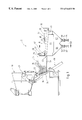
- FIG. 1 is a longitudinal section through a device for wet granulation of liquid slag according to the invention with a slag ladle in the emptying position;
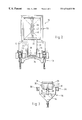
- FIG. 2 is a plan view of the device in FIG. 1 without the slag ladle;
- FIG. 3 is a cross-section along the line A—A through the device in FIG. 1 .
- reference 10 designates a slag ladle with liquid slag, which is to be granulated in a granulating device 12 according to the invention.
- This granulating device 12 consists essentially of a granulating basin 14 and a decanting basin 16 , which is attached directly to the granulating basin 14 .
- the granulating device 12 furthermore comprises a slewing device 18 for emptying the slag ladle 10 into the granulating basin 14 .
- the slewing device 18 grips the slag ladle 10 at its bearing journals 20 and slews it about a slewing axis 22 into a discharge position above the rear end face of the granulating basin 14 , such that the liquid slag can flow into the granulating basin 14 .
- the angle of inclination of the ladle 10 is adapted such that the slag flow into the granulating basin 14 is as constant as possible.
- the granulating basin 14 is formed by an oblong basin, which has a bottom surface 24 , two lateral faces 26 , 28 , as well as a rear end face 30 and a front end face 32 .
- the liquid slag flows from the slag ladle 10 into the rear end face of the granulating basin 14 .
- an injection device for the granulating water is installed in the basin. This injection device comprises a water chamber 34 , which encloses the rear end face 30 and rear section of the two lateral faces 26 and 28 .
- the granulating water is fed to the water chamber 34 via connection pieces 35 .
- the granulating water flows from the water chamber 34 into the oblong basin of the granulating basin via a large number of outlet openings 36 in the rear end face 30 and the two lateral faces 26 and 28 .
- An inflow rate in the order of about 10 m/s should be achieved at the outlet openings 36 .
- the liquid slag is caught by the granulating water flow, whereby the slag granulates and solidifies.
- the granulating basin 14 is connected to the decanting basin 16 via a device for introducing the granulate/water mixture into the decanting basin 16 , which is generally designated 38 in the figures.
- This device 38 comprises at least one tubular distributor duct 40 , which extends over the decanting basin 16 in the longitudinal direction of the latter.
- this distributor duct 40 On its underside this distributor duct 40 has outlets 42 for the granulate/water mixture, which are distributed over the length of the decanting basin 16 .
- These outlets 42 may for example comprise one or more outlet slots and/or several outlet openings arranged one behind the other.
- the outlets 42 should be arranged such that the granulate/water flow from the granulating basin through the distributor duct 40 is distributed as uniformly as possible over the full length of the decanting basin 16 .
- the distributor duct 40 is laid with a gradient, the top end forming a discharge opening 44 for the granulate/water flow in the front end face 32 of the granulating basin 14 immediately above the bottom surface 24 .
- the bottom end of the distributor duct 40 is closed and lies on a supporting base 45 on the decanting basin 16 .
- the granulating basin 14 comprises on its front end face 32 an overflow 46 , which is also connected to the distributor duct 40 by means of an overflow pipe 48 .
- screen walls 50 , 52 which extend into the decanting basin 16 to a point well below the outlets 42 in the distributor duct 40 , are mounted on both sides of the distributor duct 40 .
- These screen walls 50 , 52 form under the distributor duct 40 a vertical inflow shaft 54 open at the bottom, into which the outlets 42 for the granulate/water mixture discharge.
- the granulate/water mixture can be fed largely without turbulence into the decanting basin 16 through the distributor duct 40 , its outlets 42 and the inflow shaft 54 . This ensures that the slag granulate settles satisfactorily in the relatively small decanting basin 16 .
- the decanting basin 16 is provided at its upper edge with an overflow duct 56 for the granulating water.
- the “clarified” granulating water is withdrawn from the decanting basin 16 via this overflow duct 56 during the granulation.
- the distributor duct 40 is positioned lower and consequently below the water level 58 in the decanting basin 16 .
- the device according to the invention for introduction of the granulate/water mixture into the decanting basin 16 ensures that most of the granulate particles settle in the decanting basin 16 before the granulating water flows into the peripheral overflow duct 56 . From the overflow duct, the “clarified” granulating water can be fed back into the injection device of the granulating basin 14 .
- the latter For removal of the granulate from the granulating basin 16 the latter has in its bottom surface two funnel-shaped recesses 60 , 62 , each with an outlet connection piece 64 , 66 and a shut-off valve 68 , 70 for closing the outlet connection piece.
- the granulate accumulates in these recesses 60 , 62 and can be removed by opening the shut-off valves 68 , 70 .
- the shut-off valves 68 , 70 are preferably compression valves, i.e. valves with a diaphragm, which encloses a through duct in the valve and constricts this through duct when a pressure medium is applied.
- Upstream of each shut-off valve 68 , 70 is located a filter connection 72 , 74 , via which the decanting basin 16 is dewatered before removal of the granulate.
- the simplicity and compactness of the granulating device 12 described make it particularly suitable for use in an electric steel plant. It is of advantage that the electroslag has a relatively high specific gravity and consequently settles well in the decanting basin.
Landscapes
- Engineering & Computer Science (AREA)
- Chemical & Material Sciences (AREA)
- Manufacturing & Machinery (AREA)
- Materials Engineering (AREA)
- Metallurgy (AREA)
- Organic Chemistry (AREA)
- Manufacture Of Iron (AREA)
- Furnace Details (AREA)
- Curing Cements, Concrete, And Artificial Stone (AREA)
- Processing Of Solid Wastes (AREA)
Applications Claiming Priority (3)
| Application Number | Priority Date | Filing Date | Title |
|---|---|---|---|
| LU90255 | 1998-06-26 | ||
| LU90255A LU90255B1 (de) | 1998-06-26 | 1998-06-26 | Vorrichtung zum nassgranulieren von fluessiger Schlacke |
| PCT/EP1999/004111 WO2000000649A1 (de) | 1998-06-26 | 1999-06-15 | Vorrichtung zum nassgranulieren von flüssiger schlacke |
Publications (1)
| Publication Number | Publication Date |
|---|---|
| US6516632B1 true US6516632B1 (en) | 2003-02-11 |
Family
ID=19731754
Family Applications (1)
| Application Number | Title | Priority Date | Filing Date |
|---|---|---|---|
| US09/720,138 Expired - Fee Related US6516632B1 (en) | 1998-06-26 | 1999-06-15 | Device for wet granulation of liquid-slag |
Country Status (14)
| Country | Link |
|---|---|
| US (1) | US6516632B1 (enExample) |
| EP (1) | EP1097245B1 (enExample) |
| JP (1) | JP2003520290A (enExample) |
| CN (1) | CN1218052C (enExample) |
| AT (1) | ATE231923T1 (enExample) |
| AU (1) | AU743721B2 (enExample) |
| BR (1) | BR9911391A (enExample) |
| CA (1) | CA2334197C (enExample) |
| DE (1) | DE59904173D1 (enExample) |
| ES (1) | ES2191439T3 (enExample) |
| LU (1) | LU90255B1 (enExample) |
| TW (1) | TW426549B (enExample) |
| WO (1) | WO2000000649A1 (enExample) |
| ZA (1) | ZA200007698B (enExample) |
Cited By (1)
| Publication number | Priority date | Publication date | Assignee | Title |
|---|---|---|---|---|
| CN109338121A (zh) * | 2018-10-30 | 2019-02-15 | 铜陵有色金属集团股份有限公司金冠铜业分公司 | 翻包平台锁包装置 |
Families Citing this family (6)
| Publication number | Priority date | Publication date | Assignee | Title |
|---|---|---|---|---|
| LU90346B1 (fr) * | 1999-02-08 | 2000-08-09 | Wurth Paul Sa | Installation pour la granulation aqueuse |
| DE10148152B4 (de) * | 2001-09-28 | 2010-04-08 | Egon Evertz Kg (Gmbh & Co.) | Verfahren und Vorrichtung zum Kühlen von Pfannen- und Konverterschlacken |
| KR101147876B1 (ko) | 2004-07-14 | 2012-07-02 | 파울 부르쓰 소시에떼 아노님 | 용융체의 과립화 방법 및 장치 |
| CN1312295C (zh) * | 2005-06-23 | 2007-04-25 | 天津市隆安冶金机械厂 | 气提转毂法高炉炉渣冲制工艺及其冲制装置 |
| JP6414123B2 (ja) * | 2016-03-31 | 2018-10-31 | Jfeスチール株式会社 | スラリーディストリビューター |
| CN111575420B (zh) * | 2020-07-06 | 2022-02-18 | 付光明 | 一种环保节能型高炉熔渣的处理方法及专用处理设备 |
Citations (4)
| Publication number | Priority date | Publication date | Assignee | Title |
|---|---|---|---|---|
| US1416069A (en) | 1912-03-29 | 1922-05-16 | Schumacher Wilhelm | Method of obtaining granular slag |
| US2210999A (en) | 1937-12-20 | 1940-08-13 | Bartholomew Tracy | Production of dry granulated slag |
| DE1458808A1 (de) | 1965-11-05 | 1969-02-06 | Acieries Et Minieres De La Sam | Verfahren und Vorrichtung zum Granulieren von Schlacke |
| DE2157653A1 (de) | 1971-11-20 | 1973-05-30 | Knapsack Ag | Verfahren und vorrichtung zur ueberfuehrung fluessiger ofenschlacke in granulierte form |
-
1998
- 1998-06-26 LU LU90255A patent/LU90255B1/de active
- 1998-11-11 TW TW087118750A patent/TW426549B/zh not_active IP Right Cessation
-
1999
- 1999-06-15 JP JP2000557002A patent/JP2003520290A/ja active Pending
- 1999-06-15 CN CN998073504A patent/CN1218052C/zh not_active Expired - Fee Related
- 1999-06-15 BR BR9911391-0A patent/BR9911391A/pt not_active IP Right Cessation
- 1999-06-15 US US09/720,138 patent/US6516632B1/en not_active Expired - Fee Related
- 1999-06-15 AT AT99929210T patent/ATE231923T1/de active
- 1999-06-15 CA CA002334197A patent/CA2334197C/en not_active Expired - Fee Related
- 1999-06-15 ES ES99929210T patent/ES2191439T3/es not_active Expired - Lifetime
- 1999-06-15 AU AU46103/99A patent/AU743721B2/en not_active Ceased
- 1999-06-15 WO PCT/EP1999/004111 patent/WO2000000649A1/de not_active Ceased
- 1999-06-15 DE DE59904173T patent/DE59904173D1/de not_active Expired - Lifetime
- 1999-06-15 EP EP99929210A patent/EP1097245B1/de not_active Expired - Lifetime
-
2000
- 2000-12-20 ZA ZA200007698A patent/ZA200007698B/en unknown
Patent Citations (4)
| Publication number | Priority date | Publication date | Assignee | Title |
|---|---|---|---|---|
| US1416069A (en) | 1912-03-29 | 1922-05-16 | Schumacher Wilhelm | Method of obtaining granular slag |
| US2210999A (en) | 1937-12-20 | 1940-08-13 | Bartholomew Tracy | Production of dry granulated slag |
| DE1458808A1 (de) | 1965-11-05 | 1969-02-06 | Acieries Et Minieres De La Sam | Verfahren und Vorrichtung zum Granulieren von Schlacke |
| DE2157653A1 (de) | 1971-11-20 | 1973-05-30 | Knapsack Ag | Verfahren und vorrichtung zur ueberfuehrung fluessiger ofenschlacke in granulierte form |
Cited By (1)
| Publication number | Priority date | Publication date | Assignee | Title |
|---|---|---|---|---|
| CN109338121A (zh) * | 2018-10-30 | 2019-02-15 | 铜陵有色金属集团股份有限公司金冠铜业分公司 | 翻包平台锁包装置 |
Also Published As
| Publication number | Publication date |
|---|---|
| EP1097245A1 (de) | 2001-05-09 |
| AU743721B2 (en) | 2002-01-31 |
| ES2191439T3 (es) | 2003-09-01 |
| AU4610399A (en) | 2000-01-17 |
| CA2334197A1 (en) | 2000-01-06 |
| ZA200007698B (en) | 2001-06-21 |
| ATE231923T1 (de) | 2003-02-15 |
| CN1305533A (zh) | 2001-07-25 |
| CA2334197C (en) | 2008-08-12 |
| TW426549B (en) | 2001-03-21 |
| WO2000000649A1 (de) | 2000-01-06 |
| DE59904173D1 (de) | 2003-03-06 |
| CN1218052C (zh) | 2005-09-07 |
| JP2003520290A (ja) | 2003-07-02 |
| LU90255B1 (de) | 2000-01-03 |
| EP1097245B1 (de) | 2003-01-29 |
| BR9911391A (pt) | 2001-03-13 |
Similar Documents
| Publication | Publication Date | Title |
|---|---|---|
| US4125146A (en) | Continuous casting processes and apparatus | |
| US6516632B1 (en) | Device for wet granulation of liquid-slag | |
| US3615329A (en) | A recirculatory system for the granulation of molten slag | |
| CA1136365A (en) | Method of hauling granulates and similar material and apparatus for performing the method | |
| MXPA01000088A (en) | Method for wet granulation of liquid-slag | |
| CA1169247A (en) | Apparatus for refining molten aluminum | |
| CN1985009B (zh) | 用于熔融物造粒的方法和装置 | |
| JPS5913885B2 (ja) | 細密除塵器 | |
| JP2003520290A5 (enExample) | ||
| JPS6036336B2 (ja) | 水平連続鋳造におけるブレ−クアウト発生時の流出溶鋼処理設備 | |
| JP3363548B2 (ja) | 冷却槽の集塵装置 | |
| US2139949A (en) | Apparatus for handling molten slag | |
| CA2360211C (en) | Installation for aqueous granulation | |
| AU2002238481B2 (en) | Tank for draining a granular material/liquid mixture | |
| JPS6383208A (ja) | 高炉銑滓分離方法 | |
| US2733810A (en) | murry | |
| JPS6393466A (ja) | 注湯取鍋用溶湯注入器 | |
| SU945116A1 (ru) | Установка дл получени гранулированного шлака | |
| SU1146090A2 (ru) | Классификатор | |
| SU1025728A1 (ru) | Главный желоб доменной печи | |
| SU1627560A1 (ru) | Шлакова чаша | |
| SU753809A1 (ru) | Установка дл переработки жидкого доменного шлака | |
| SU1392113A1 (ru) | Установка дл модифицировани чугуна | |
| SU654563A1 (ru) | Устройство дл гранул ции шлакового расплава | |
| JPS62155400A (ja) | スラリ−均等分配装置 |
Legal Events
| Date | Code | Title | Description |
|---|---|---|---|
| AS | Assignment |
Owner name: WURTH, S.A. PAUL, LUXEMBOURG Free format text: ASSIGNMENT OF ASSIGNORS INTEREST;ASSIGNORS:ULVELING, LEON;ROTH, JEAN-LUC;RADOUX, HENRI;REEL/FRAME:011495/0617 Effective date: 20001214 |
|
| CC | Certificate of correction | ||
| FPAY | Fee payment |
Year of fee payment: 4 |
|
| FPAY | Fee payment |
Year of fee payment: 8 |
|
| REMI | Maintenance fee reminder mailed | ||
| LAPS | Lapse for failure to pay maintenance fees | ||
| STCH | Information on status: patent discontinuation |
Free format text: PATENT EXPIRED DUE TO NONPAYMENT OF MAINTENANCE FEES UNDER 37 CFR 1.362 |
|
| FP | Lapsed due to failure to pay maintenance fee |
Effective date: 20150211 |