US6460880B1 - Method of forming a motor vehicle instrument panel with a flexibly tethered air bag deployment door - Google Patents
Method of forming a motor vehicle instrument panel with a flexibly tethered air bag deployment door Download PDFInfo
- Publication number
- US6460880B1 US6460880B1 US09/127,681 US12768198A US6460880B1 US 6460880 B1 US6460880 B1 US 6460880B1 US 12768198 A US12768198 A US 12768198A US 6460880 B1 US6460880 B1 US 6460880B1
- Authority
- US
- United States
- Prior art keywords
- panel
- door
- hinge
- air bag
- integral
- Prior art date
- Legal status (The legal status is an assumption and is not a legal conclusion. Google has not performed a legal analysis and makes no representation as to the accuracy of the status listed.)
- Expired - Fee Related
Links
Images


Classifications
-
- B—PERFORMING OPERATIONS; TRANSPORTING
- B29—WORKING OF PLASTICS; WORKING OF SUBSTANCES IN A PLASTIC STATE IN GENERAL
- B29C—SHAPING OR JOINING OF PLASTICS; SHAPING OF MATERIAL IN A PLASTIC STATE, NOT OTHERWISE PROVIDED FOR; AFTER-TREATMENT OF THE SHAPED PRODUCTS, e.g. REPAIRING
- B29C37/00—Component parts, details, accessories or auxiliary operations, not covered by group B29C33/00 or B29C35/00
- B29C37/0053—Moulding articles characterised by the shape of the surface, e.g. ribs, high polish
- B29C37/0057—Moulding single grooves or ribs, e.g. tear lines
-
- B—PERFORMING OPERATIONS; TRANSPORTING
- B29—WORKING OF PLASTICS; WORKING OF SUBSTANCES IN A PLASTIC STATE IN GENERAL
- B29C—SHAPING OR JOINING OF PLASTICS; SHAPING OF MATERIAL IN A PLASTIC STATE, NOT OTHERWISE PROVIDED FOR; AFTER-TREATMENT OF THE SHAPED PRODUCTS, e.g. REPAIRING
- B29C39/00—Shaping by casting, i.e. introducing the moulding material into a mould or between confining surfaces without significant moulding pressure; Apparatus therefor
- B29C39/02—Shaping by casting, i.e. introducing the moulding material into a mould or between confining surfaces without significant moulding pressure; Apparatus therefor for making articles of definite length, i.e. discrete articles
- B29C39/12—Making multilayered or multicoloured articles
- B29C39/123—Making multilayered articles
-
- B—PERFORMING OPERATIONS; TRANSPORTING
- B29—WORKING OF PLASTICS; WORKING OF SUBSTANCES IN A PLASTIC STATE IN GENERAL
- B29C—SHAPING OR JOINING OF PLASTICS; SHAPING OF MATERIAL IN A PLASTIC STATE, NOT OTHERWISE PROVIDED FOR; AFTER-TREATMENT OF THE SHAPED PRODUCTS, e.g. REPAIRING
- B29C45/00—Injection moulding, i.e. forcing the required volume of moulding material through a nozzle into a closed mould; Apparatus therefor
- B29C45/16—Making multilayered or multicoloured articles
-
- B—PERFORMING OPERATIONS; TRANSPORTING
- B60—VEHICLES IN GENERAL
- B60R—VEHICLES, VEHICLE FITTINGS, OR VEHICLE PARTS, NOT OTHERWISE PROVIDED FOR
- B60R11/00—Arrangements for holding or mounting articles, not otherwise provided for
- B60R11/02—Arrangements for holding or mounting articles, not otherwise provided for for radio sets, television sets, telephones, or the like; Arrangement of controls thereof
-
- B—PERFORMING OPERATIONS; TRANSPORTING
- B60—VEHICLES IN GENERAL
- B60R—VEHICLES, VEHICLE FITTINGS, OR VEHICLE PARTS, NOT OTHERWISE PROVIDED FOR
- B60R13/00—Elements for body-finishing, identifying, or decorating; Arrangements or adaptations for advertising purposes
- B60R13/02—Internal Trim mouldings ; Internal Ledges; Wall liners for passenger compartments; Roof liners
- B60R13/0262—Mid-console liners
-
- B—PERFORMING OPERATIONS; TRANSPORTING
- B60—VEHICLES IN GENERAL
- B60R—VEHICLES, VEHICLE FITTINGS, OR VEHICLE PARTS, NOT OTHERWISE PROVIDED FOR
- B60R21/00—Arrangements or fittings on vehicles for protecting or preventing injuries to occupants or pedestrians in case of accidents or other traffic risks
- B60R21/02—Occupant safety arrangements or fittings, e.g. crash pads
- B60R21/16—Inflatable occupant restraints or confinements designed to inflate upon impact or impending impact, e.g. air bags
- B60R21/20—Arrangements for storing inflatable members in their non-use or deflated condition; Arrangement or mounting of air bag modules or components
- B60R21/215—Arrangements for storing inflatable members in their non-use or deflated condition; Arrangement or mounting of air bag modules or components characterised by the covers for the inflatable member
- B60R21/216—Arrangements for storing inflatable members in their non-use or deflated condition; Arrangement or mounting of air bag modules or components characterised by the covers for the inflatable member comprising tether means for limitation of cover motion during deployment
-
- B—PERFORMING OPERATIONS; TRANSPORTING
- B60—VEHICLES IN GENERAL
- B60R—VEHICLES, VEHICLE FITTINGS, OR VEHICLE PARTS, NOT OTHERWISE PROVIDED FOR
- B60R21/00—Arrangements or fittings on vehicles for protecting or preventing injuries to occupants or pedestrians in case of accidents or other traffic risks
- B60R21/02—Occupant safety arrangements or fittings, e.g. crash pads
- B60R21/16—Inflatable occupant restraints or confinements designed to inflate upon impact or impending impact, e.g. air bags
- B60R21/20—Arrangements for storing inflatable members in their non-use or deflated condition; Arrangement or mounting of air bag modules or components
- B60R21/215—Arrangements for storing inflatable members in their non-use or deflated condition; Arrangement or mounting of air bag modules or components characterised by the covers for the inflatable member
- B60R21/2165—Arrangements for storing inflatable members in their non-use or deflated condition; Arrangement or mounting of air bag modules or components characterised by the covers for the inflatable member characterised by a tear line for defining a deployment opening
-
- B—PERFORMING OPERATIONS; TRANSPORTING
- B29—WORKING OF PLASTICS; WORKING OF SUBSTANCES IN A PLASTIC STATE IN GENERAL
- B29L—INDEXING SCHEME ASSOCIATED WITH SUBCLASS B29C, RELATING TO PARTICULAR ARTICLES
- B29L2031/00—Other particular articles
- B29L2031/30—Vehicles, e.g. ships or aircraft, or body parts thereof
- B29L2031/3005—Body finishings
- B29L2031/3038—Air bag covers
-
- B—PERFORMING OPERATIONS; TRANSPORTING
- B60—VEHICLES IN GENERAL
- B60R—VEHICLES, VEHICLE FITTINGS, OR VEHICLE PARTS, NOT OTHERWISE PROVIDED FOR
- B60R11/00—Arrangements for holding or mounting articles, not otherwise provided for
- B60R11/02—Arrangements for holding or mounting articles, not otherwise provided for for radio sets, television sets, telephones, or the like; Arrangement of controls thereof
- B60R11/0205—Arrangements for holding or mounting articles, not otherwise provided for for radio sets, television sets, telephones, or the like; Arrangement of controls thereof for radio sets
-
- B—PERFORMING OPERATIONS; TRANSPORTING
- B60—VEHICLES IN GENERAL
- B60R—VEHICLES, VEHICLE FITTINGS, OR VEHICLE PARTS, NOT OTHERWISE PROVIDED FOR
- B60R11/00—Arrangements for holding or mounting articles, not otherwise provided for
- B60R11/02—Arrangements for holding or mounting articles, not otherwise provided for for radio sets, television sets, telephones, or the like; Arrangement of controls thereof
- B60R11/0211—Arrangements for holding or mounting articles, not otherwise provided for for radio sets, television sets, telephones, or the like; Arrangement of controls thereof for record carriers apparatus, e.g. video recorders, tape players or CD players
-
- B—PERFORMING OPERATIONS; TRANSPORTING
- B60—VEHICLES IN GENERAL
- B60R—VEHICLES, VEHICLE FITTINGS, OR VEHICLE PARTS, NOT OTHERWISE PROVIDED FOR
- B60R11/00—Arrangements for holding or mounting articles, not otherwise provided for
- B60R11/02—Arrangements for holding or mounting articles, not otherwise provided for for radio sets, television sets, telephones, or the like; Arrangement of controls thereof
- B60R11/0229—Arrangements for holding or mounting articles, not otherwise provided for for radio sets, television sets, telephones, or the like; Arrangement of controls thereof for displays, e.g. cathodic tubes
-
- B—PERFORMING OPERATIONS; TRANSPORTING
- B60—VEHICLES IN GENERAL
- B60R—VEHICLES, VEHICLE FITTINGS, OR VEHICLE PARTS, NOT OTHERWISE PROVIDED FOR
- B60R11/00—Arrangements for holding or mounting articles, not otherwise provided for
- B60R11/02—Arrangements for holding or mounting articles, not otherwise provided for for radio sets, television sets, telephones, or the like; Arrangement of controls thereof
- B60R11/0252—Arrangements for holding or mounting articles, not otherwise provided for for radio sets, television sets, telephones, or the like; Arrangement of controls thereof for personal computers, e.g. laptops, notebooks
-
- B—PERFORMING OPERATIONS; TRANSPORTING
- B60—VEHICLES IN GENERAL
- B60R—VEHICLES, VEHICLE FITTINGS, OR VEHICLE PARTS, NOT OTHERWISE PROVIDED FOR
- B60R13/00—Elements for body-finishing, identifying, or decorating; Arrangements or adaptations for advertising purposes
- B60R13/02—Internal Trim mouldings ; Internal Ledges; Wall liners for passenger compartments; Roof liners
- B60R13/0275—Internal Trim mouldings ; Internal Ledges; Wall liners for passenger compartments; Roof liners comprising removable or hinged parts
-
- B—PERFORMING OPERATIONS; TRANSPORTING
- B60—VEHICLES IN GENERAL
- B60R—VEHICLES, VEHICLE FITTINGS, OR VEHICLE PARTS, NOT OTHERWISE PROVIDED FOR
- B60R13/00—Elements for body-finishing, identifying, or decorating; Arrangements or adaptations for advertising purposes
- B60R13/08—Insulating elements, e.g. for sound insulation
- B60R13/0815—Acoustic or thermal insulation of passenger compartments
-
- B—PERFORMING OPERATIONS; TRANSPORTING
- B60—VEHICLES IN GENERAL
- B60R—VEHICLES, VEHICLE FITTINGS, OR VEHICLE PARTS, NOT OTHERWISE PROVIDED FOR
- B60R13/00—Elements for body-finishing, identifying, or decorating; Arrangements or adaptations for advertising purposes
- B60R13/08—Insulating elements, e.g. for sound insulation
- B60R13/0846—Insulating elements, e.g. for sound insulation for duct, cable or rod passages, e.g. between engine and passenger compartments
-
- B—PERFORMING OPERATIONS; TRANSPORTING
- B60—VEHICLES IN GENERAL
- B60R—VEHICLES, VEHICLE FITTINGS, OR VEHICLE PARTS, NOT OTHERWISE PROVIDED FOR
- B60R11/00—Arrangements for holding or mounting articles, not otherwise provided for
- B60R2011/0001—Arrangements for holding or mounting articles, not otherwise provided for characterised by position
- B60R2011/0003—Arrangements for holding or mounting articles, not otherwise provided for characterised by position inside the vehicle
- B60R2011/0005—Dashboard
-
- B—PERFORMING OPERATIONS; TRANSPORTING
- B60—VEHICLES IN GENERAL
- B60R—VEHICLES, VEHICLE FITTINGS, OR VEHICLE PARTS, NOT OTHERWISE PROVIDED FOR
- B60R11/00—Arrangements for holding or mounting articles, not otherwise provided for
- B60R2011/0001—Arrangements for holding or mounting articles, not otherwise provided for characterised by position
- B60R2011/0003—Arrangements for holding or mounting articles, not otherwise provided for characterised by position inside the vehicle
- B60R2011/0007—Mid-console
-
- B—PERFORMING OPERATIONS; TRANSPORTING
- B60—VEHICLES IN GENERAL
- B60R—VEHICLES, VEHICLE FITTINGS, OR VEHICLE PARTS, NOT OTHERWISE PROVIDED FOR
- B60R11/00—Arrangements for holding or mounting articles, not otherwise provided for
- B60R2011/0042—Arrangements for holding or mounting articles, not otherwise provided for characterised by mounting means
- B60R2011/0043—Arrangements for holding or mounting articles, not otherwise provided for characterised by mounting means for integrated articles, i.e. not substantially protruding from the surrounding parts
- B60R2011/0045—Arrangements for holding or mounting articles, not otherwise provided for characterised by mounting means for integrated articles, i.e. not substantially protruding from the surrounding parts with visible part, e.g. flush mounted
-
- B—PERFORMING OPERATIONS; TRANSPORTING
- B60—VEHICLES IN GENERAL
- B60R—VEHICLES, VEHICLE FITTINGS, OR VEHICLE PARTS, NOT OTHERWISE PROVIDED FOR
- B60R11/00—Arrangements for holding or mounting articles, not otherwise provided for
- B60R2011/0042—Arrangements for holding or mounting articles, not otherwise provided for characterised by mounting means
- B60R2011/008—Adjustable or movable supports
- B60R2011/0082—Adjustable or movable supports collapsible, e.g. for storing after use
-
- B—PERFORMING OPERATIONS; TRANSPORTING
- B60—VEHICLES IN GENERAL
- B60R—VEHICLES, VEHICLE FITTINGS, OR VEHICLE PARTS, NOT OTHERWISE PROVIDED FOR
- B60R11/00—Arrangements for holding or mounting articles, not otherwise provided for
- B60R2011/0042—Arrangements for holding or mounting articles, not otherwise provided for characterised by mounting means
- B60R2011/008—Adjustable or movable supports
- B60R2011/0092—Adjustable or movable supports with motorization
-
- B—PERFORMING OPERATIONS; TRANSPORTING
- B60—VEHICLES IN GENERAL
- B60R—VEHICLES, VEHICLE FITTINGS, OR VEHICLE PARTS, NOT OTHERWISE PROVIDED FOR
- B60R11/00—Arrangements for holding or mounting articles, not otherwise provided for
- B60R2011/0094—Arrangements for holding or mounting articles, not otherwise provided for characterised by means for covering after user, e.g. boxes, shutters or the like
-
- B—PERFORMING OPERATIONS; TRANSPORTING
- B60—VEHICLES IN GENERAL
- B60R—VEHICLES, VEHICLE FITTINGS, OR VEHICLE PARTS, NOT OTHERWISE PROVIDED FOR
- B60R11/00—Arrangements for holding or mounting articles, not otherwise provided for
- B60R2011/0096—Theft prevention of articles
-
- B—PERFORMING OPERATIONS; TRANSPORTING
- B60—VEHICLES IN GENERAL
- B60R—VEHICLES, VEHICLE FITTINGS, OR VEHICLE PARTS, NOT OTHERWISE PROVIDED FOR
- B60R11/00—Arrangements for holding or mounting articles, not otherwise provided for
- B60R11/02—Arrangements for holding or mounting articles, not otherwise provided for for radio sets, television sets, telephones, or the like; Arrangement of controls thereof
- B60R2011/0276—Arrangements for holding or mounting articles, not otherwise provided for for radio sets, television sets, telephones, or the like; Arrangement of controls thereof for rear passenger use
-
- B—PERFORMING OPERATIONS; TRANSPORTING
- B60—VEHICLES IN GENERAL
- B60R—VEHICLES, VEHICLE FITTINGS, OR VEHICLE PARTS, NOT OTHERWISE PROVIDED FOR
- B60R13/00—Elements for body-finishing, identifying, or decorating; Arrangements or adaptations for advertising purposes
- B60R13/02—Internal Trim mouldings ; Internal Ledges; Wall liners for passenger compartments; Roof liners
- B60R2013/0287—Internal Trim mouldings ; Internal Ledges; Wall liners for passenger compartments; Roof liners integrating other functions or accessories
-
- B—PERFORMING OPERATIONS; TRANSPORTING
- B60—VEHICLES IN GENERAL
- B60R—VEHICLES, VEHICLE FITTINGS, OR VEHICLE PARTS, NOT OTHERWISE PROVIDED FOR
- B60R21/00—Arrangements or fittings on vehicles for protecting or preventing injuries to occupants or pedestrians in case of accidents or other traffic risks
- B60R21/02—Occupant safety arrangements or fittings, e.g. crash pads
- B60R21/16—Inflatable occupant restraints or confinements designed to inflate upon impact or impending impact, e.g. air bags
- B60R21/20—Arrangements for storing inflatable members in their non-use or deflated condition; Arrangement or mounting of air bag modules or components
- B60R21/215—Arrangements for storing inflatable members in their non-use or deflated condition; Arrangement or mounting of air bag modules or components characterised by the covers for the inflatable member
- B60R2021/21537—Arrangements for storing inflatable members in their non-use or deflated condition; Arrangement or mounting of air bag modules or components characterised by the covers for the inflatable member characterised by hinges
Definitions
- This invention relates to motor vehicle instrument panels having an integral air bag deployment door defined by a tear seam and more particularly to a tether for a potentially frangible air bag door when it is separated at very low temperatures from the instrument panel and then because of cold embrittlement from a flexible hinge that is integral with the door and normally provides through bending movement for opening swinging movement of the door and its retention to the vehicle structure at higher temperatures.
- a molded motor vehicle instrument panel made of a thermoplastic material well suited for the primary purpose of such a panel has an integral air bag deployment door for a passenger side air bag that is safely retained to the vehicle structure in a very cost effective manner.
- the air bag door is defined by a tear seam in the panel and is normally retained by an integral flexible mounting/hinge flange to a part of the vehicle structure when the seam is torn by the inflating air bag and wherein this flange which before was integral with both the door and the panel is then separated from the main body of the panel while remaining integral with the door and bends to allow the door to swing open to allow deployment of the air bag through an opening in the instrument panel while retaining same to the vehicle structure as the door is then free of the instrument panel.
- a portion of the air bag door can break away from the mounting/hinge flange where it joins therewith because of plastic embrittlement at these low temperatures and the high bending stresses encountered at this juncture.
- This separation of the broken door portion from the vehicle structure is prevented by bonding a layer of second plastics material over the juncture zone and an adjoining inside surface of the potentially frangible door portion and an adjoining one side of the mounting/hinge flange.
- the second plastics material has the physical characteristic of remaining ductile to a substantial degree at low temperatures substantially below the temperature at which the first plastics material becomes brittle.
- the bonded layer thus forms a tether that tethers the frangible door portion to the mounting/hinge flange in a flexible manner when this door portion breaks away from the flange because of embrittlement of the first plastics material at the low temperatures on tearing of the tear seam and opening movement of the door by the inflating air bag pressing against the inside surface of the frangible door portion.
- This allows the broken door portion to continue movement in it opening direction to allow continued deployment of the air bag while the broken door portion remains connected by the flexible tether to the mounting/hinge flange and thereby the vehicle structure.
- the instrument panel and the air bag deployment door tethering layer may be formed in various ways including injection molding the panel and injection molding, spraying or low pressure molding the tethering layer in a second step.
- Such formation of the tether in place as a bonded layer is particularly advantageous from both a cost and production standpoint as it becomes integral with the instrument panel and there is no need to inventory a separate tether that must then be fastened by some form of fastening means to both the mounting/hinge flange and the door.
- the bonding of the tethering layer to the inside surface of the door hides its presence from view which is desirable from an appearance or styling standpoint.
- Another object is to provide a new and improved method of forming a motor vehicle instrument panel with an integral air bag deployment door and a flexible tether for the door at low cost and of high quality and to meet certain styling desires.
- Another object is to provide a method of forming a motor vehicle instrument panel with a tethered air bag deployment door wherein the panel including the door is formed of a plastics material suited to meet the requirements of an instrument panel and the tether is formed of a layer of plastics material that spans a potential fracture zone in the door and remains ductile at low temperatures that cause embrittlement of the door that could result in the fracturing of a portion of the door at thus fracture zone on air bag deployment and loss of its retention to the vehicle structure but for the tethering layer.
- Another object is to provide a method of forming a motor vehicle instrument panel including an air bag deployment door that is defined by a tear seam molded in the panel wherein the panel is formed of a plastics material suited to its requirements and the door is retained to the vehicle structure on breaking away at very cold temperatures by a flexible layer of plastics material that is formed in place over an inside surface of the door and one side of a mounting/hinge flange that is molded integral with the inside surface of the door and normally retains the air bag door to the vehicle structure on opening movement.
- Another object is to provide a low cost, high quality motor vehicle instrument panel with flexibly tethered air bag deployment door produced by the above method.
- a second aspect of the present invention includes an automotive air bag cover assembly comprising a hinge panel that is connected, in a layered disposition, to an inside surface of at least one of the integral air bag cover and instrument panel.
- the instrument panel comprises a first plastics material and is configured to mount in the passenger compartment of the motor vehicle.
- the air bag door panel also comprises the first plastics material and is formed with the instrument panel as a single integral panel.
- the door panel is at least partially surrounded by the instrument panel.
- Another object of the second aspect of the present invention is to provide a hinge panel to act as a primary hinge between the door panel and the instrument panel during air bag deployment.
- the hinge panel spans a panel juncture zone between the door panel and the instrument panel.
- Another object of the second aspect of the present invention is to aid in bending the first plastics material at the hinge location by providing a panel juncture zone that includes a styling groove separating at least a portion of the door panel and the instrument panel.
- the styling groove may also function as a tear seam.
- Another object of the second aspect of the present invention is to guide tearing around the door panel when the air bag inflates by providing a panel juncture zone that includes a weakened tear seam separating at least a portion of the door panel and the instrument panel.
- Another object of the second aspect of the present invention is to provide a hinge that includes a hinge panel edge aligned with at least a portion of the tear seam to act in guiding tearing along the tear seam as the door is forced open during air bag inflation.
- Another object of the second aspect of the present invention is to prevent hinge panel fracture at low temperatures by providing a hinge panel comprising a second plastics material that is more ductile and less brittle at low temperatures than the first plastics material.
- Another object of the second aspect of the present invention is to prevent hinge panel fracture by providing a hinge panel comprising metal.
- Another object of the second aspect of the present invention is to provide a means of securing the door panel to a structural member during deployment by providing a hinge flange that extends transversely inward from the inside surface of the door panel.
- the hinge flange is configured to secure the door panel to a structural member.
- the hinge panel spans a juncture zone between the hinge flange and door panel in a layered disposition with a portion of the hinge panel being attached to the hinge flange.
- Another object of the second aspect of the present invention is to provide a means for supporting an air bag canister assembly on the instrument panel by providing a collar that extends transversely inward from the inside surface of the instrument panel and from around the door panel.
- the collar defines a door-collar interface along the region where the collar extends from the panel.
- the hinge panel spans the door-collar interface, one portion of the hinge panel being attached to the collar and another portion of the hinge panel being attached to the door panel.
- Another object of the second aspect of the present invention is to provide a method for making an air bag cover assembly.
- the method includes providing a mold having first and second mold portions.
- the first and second mold portions form a mold cavity when closed together.
- the mold cavity has a shape that complements the shape of the integral instrument and door panel and the hinge panel.
- the hinge panel is placed in the second mold portion.
- the mold is then closed and the first plastics material is introduced into the mold cavity in molten form.
- the molten first plastics material is then allowed to conform to the shape of the mold cavity and to solidify in the mold cavity.
- the mold is then opened and the completed assembly is removed from the mold.
- the method may also include formation of the hinge panel from the second plastics material and the selection of a second plastic material that is more ductile and less brittle at low temperatures than the first plastics material.
- the method may alternatively include the provision of a hinge panel comprising metal.
- a hinge panel comprising metal.
- metal is generally preferred over plastic due to increased rigidity which aids in evenly distributing door opening forces along a tear seam to promote more uniform tear seam fracture and subsequent door opening.
- the method may also include the placement of the hinge panel on the mold cavity surface of the second mold portion in a position spanning a portion of the mold configured to form the panel juncture zone between the instrument panel and door panel portions of the integral panel.
- the mold cavity surface of the second mold portion may be shaped to form a hinge-flange that protrudes transversely inward from the door panel portion of the integral panel.
- the hinge panel is placed on the mold cavity surface of the second mold portion in a position spanning a portion of the mold configured to form a flange juncture zone between the hinge-flange and the door panel.
- FIG. 1 is a perspective view of a motor vehicle instrument panel including integral air bag deployment door with a flexible tether made according to the present invention and as installed in a motor vehicle over an air bag system;
- FIG. 2 is an enlarged view taken along the line 2 — 2 in FIG. 1 when looking in the direction of the arrows;
- FIG. 3 is a view taken along the line 3 — 3 in FIG. 2 when looking in the direction of the arrows;
- FIG. 4 is a view like FIG. 2 but showing the air bag door opened and broken during the deployment of the air bag at a very low temperature;
- FIG. 5 is a fragmentary perspective view of mold tools used to mold the flexible tethering layer in FIGS. 2 and 3 and includes a sectional view of the instrument panel as molded and then located between these tools for the molding of the flexible tethering layer;
- FIG. 6 is view taken along the line 6 — 6 in FIG. 5 when looking in the direction of the arrows;
- FIG. 7 is a sectional view of the instrument panel as molded without the flexible tethering layer and includes a diagrammatic view of spraying apparatus for forming the flexible tethering layer;
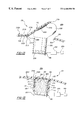
- FIG. 8 is a cross-sectional side view of a motor vehicle instrument panel constructed according to the invention and including an integral air bag deployment door in a closed position, a plastic insert molded hinge and an integral mounting/hinge flange;
- FIG. 9 is a cross-sectional side view of the instrument panel of FIG. 8 with the air bag deployment door being moved out of the closed position by an inflating air bag;
- FIG. 10 is a cross-sectional side view of the instrument panel of FIGS. 8 and 9 with the air bag deployment door being fractured as it is moved out of the closed position by an inflating air bag;
- FIG. 11 is a perspective view of a motor vehicle instrument panel including integral air bag deployment door having a plastic insert molded hinge constructed according to the present invention and as installed in a motor vehicle over an air bag system;
- FIG. 12 is a cross-sectional side view of the instrument panel and air bag system of FIG. 11 with the air bag deployment door in a closed position;
- FIG. 13 is a cross-sectional side view of the instrument panel and air bag system of FIG. 11 with the air bag deployment door being moved out of the closed position by air bag inflation;
- FIG. 14 is a cross-sectional side view of a motor vehicle instrument panel constructed according to the invention and including an integral air bag deployment door and including a metal insert molded hinge;
- FIG. 15 is a cross-sectional side view of a motor vehicle instrument panel constructed according to the invention and including a collar extending transversely inward from an inside surface of the instrument panel, an integral air bag deployment door in a closed position and a plastic insert molded hinge.
- FIGS. 1-4 there is illustrated a molded instrument panel air bag cover assembly 10 for concealing an inflatable air bag system of a motor vehicle.
- the motor vehicle structure is generally designated as 11 .
- Alternative embodiments of the instrument panel cover assembly 10 are generally shown at 10 a in FIGS. 8-10, 10 b in FIGS. 11-14, and 10 c in FIG. 15 .
- Reference numerals with the suffix “a” in FIGS. 8-10, the suffix “b” in FIGS. 11-14 and the suffix “c” in FIG. 15 designate the alternative configuration of each element common to the embodiment of FIGS. 1-4. Unless the description indicates otherwise, where the description uses a reference numeral to refers to an element in FIGS. 1-4, I intend that portion of the description to apply equally to elements in FIGS. 8-10, 11 - 14 and 15 ; indicated by the same reference numeral with the suffix “a”, “b” or “C”; respectively.
- the cover assembly 10 has a contoured section 12 on the driver side for the installation of an instrument cluster (not shown) and an air bag deployment door 14 of rectangular shape on the passenger side that is defined by a tear seam 16 molded in the cover assembly.
- the tear seam 16 may be formed by a groove either in the face of the panel as shown or by a similar groove in the back side of the panel to hide the tear seam from view as is well known in the art.
- the cover assembly covers an air bag system 18 that is located behind the cover assembly directly behind the air bag door 14 and is mounted on a sheet metal portion 20 of the vehicle structure at the front of the passenger compartment.
- the air bag system 18 is of a conventional type that includes an inflatable air bag 22 , a gas generator 24 and a controller 26 that includes a vehicle impact sensor and triggers ignition of the gas generator to inflate the air bag for deployment into the passenger space 28 directly in front of a passenger seated on this side.
- the cover assembly 10 is a molded one-piece part of generally uniform wall thickness and is formed of a suitable thermoplastic material such as styrene-maleic anhydride, polypropylene, polycarbonate, polyphenylene oxide and polyurethane that provides sufficient stiffness so that the panel is self-supporting to maintain the desired shape and has sufficient heat resistance to resist deformation due to heat in its interior vehicle environment where it is located immediately behind the windshield (not shown).
- a suitable thermoplastic material such as styrene-maleic anhydride, polypropylene, polycarbonate, polyphenylene oxide and polyurethane that provides sufficient stiffness so that the panel is self-supporting to maintain the desired shape and has sufficient heat resistance to resist deformation due to heat in its interior vehicle environment where it is located immediately behind the windshield (not shown).
- the cover assembly may be molded in various conventional ways including injection molding as is well known in the art.
- the groove forming the tear seam 16 is made deep enough in relation to the wall thickness of the cover assembly and the strength of the plastic material used so as to sufficiently weaken the wall section at the tear seam to the point that it is torn by the force of the inflating air bag acting against the back or inside surface of the air bag door and creates on its separation from the cover assembly an opening 30 therein for the deployment of the air bag as illustrated in FIG. 4 and described in more detail later.
- the cover assembly 10 is fastened to portions of the vehicle structure 11 at various locations outside the area of the air bag door with one such location being shown in FIG. 2 wherein a sheet metal screw 32 fastens the panel at a lower edge thereof beneath the air bag door to a sheet metal portion 34 of the vehicle structure.
- a sheet metal screw 32 fastens the panel at a lower edge thereof beneath the air bag door to a sheet metal portion 34 of the vehicle structure.
- similar screws or other conventional type fasteners are used at other locations outside the area of the air bag door to securely fasten the cover assembly in place on the vehicle structure.
- the air bag deployment door 14 in the cover assembly 10 is separately fastened to the vehicle structure by an elongated mounting/hinge flange 36 that is molded integral with the back inside surface of the door and extends horizontally along substantially the entire length and adjacent to the upper edge thereof as seen in FIGS. 1-3.
- the flange 36 has a flat rectangular portion 38 that extends inwardly of the door a substantial distance and terminates in a flat, rectangular, angled, horizontally extending, distal portion 40 that is fastened along its length by bolts 42 to a sheet metal portion 44 of the vehicle structure.
- the flange 36 is also formed with a controlled thickness and is capable of elastic bending to a significant degree in the rectangular portion 38 in a certain substantial temperature range and down to a certain low temperature (e.g. ⁇ 20° F.) without breaking and thereby act as a cantilever hinge to normally provide for outward swinging opening movement of the door when the door is separated along the tear seam from the cover assembly for air bag deployment.
- a certain low temperature e.g. ⁇ 20° F.
- the flange 36 acts to fasten the cover assembly to the vehicle structure at the air bag door and also provides support for the latter against a pushing force such as from a passenger which could otherwise push the door inward and separate the door from the cover assembly along the tear seam.
- the flange 36 is designed to normally hinge and retain the air bag door 14 to the vehicle structure during its outward opening movement when the tear seam 16 is torn by the force of the inflating air bag and in doing so is highly stressed at its juncture 48 with the door as the flange portion 38 bends to effect swinging movement of the door.
- the typical plastic material suitable for the cover assembly in its primary application can become brittle to the point where the lower and major portion 46 of the door, that is forced by the inflating air bag to bend outward about the horizontally extending juncture 48 of the door with the flange 36 , may fracture or break off at this highly stressed location or zone (see FIG.
- a flexible door tethering layer 50 of controlled thickness that is formed in place over the one side 52 of the mounting/hinge flange 36 adjoining the potential fracture zone 48 , over this zone, and over the inside surface 54 of the potentially frangible door portion 46 .
- the material forming the door tethering layer 50 is a flexible plastics material of a prescribed controlled thickness that is formed in place as described in more detail latter, bonds in its formation without an added adhesive to the material of the cover assembly, and remains flexible or ductile at temperatures substantially below that at which the material of the cover assembly 10 including the integral air bag deployment door 14 becomes brittle.
- tethering layer 50 examples include polyurethane elastomers, polyester elastomers, and polyolefin elastomers.
- tethering material while well suited for its application is not suited to meet the stiff requirements of the cover assembly.
- the flexible tethering layer 50 extends horizontally substantially the entire length of the mounting/hinge flange 36 and is bonded to the side 52 of the flat flange portion 38 at a margin portion 56 of the tethering layer that extends laterally to the distal flange portion 40 so as to maximize the bonding area on this side of the potential fracture zone 48 and thereby maximize the retention of the tethering layer to the flange 36 .
- the tethering layer 50 spans and is bonded to the potential fracture zone 48 at an intermediate portion 58 of the tethering layer and is bonded to the inside surface 54 of the potentially frangible air bag door portion 46 at a margin portion 60 that extends laterally to near the lower edge of the door so as to maximize the bonding area of the tethering layer with this door portion and its retention to the flange 36 .
- the tethering layer 50 at its intermediate portion 58 that spans the potential fracture zone flexes when door breakage occurs because of cold plastic embrittlement to permit the broken door portion 46 to continue to swing outward and upward about the line of fracture at the flange 36 to provide for continued air bag deployment while retaining the broken door portion safely to the vehicle structure with the tethering layer 50 and flange 36 .
- the bonded retention of the tethering layer over substantially the entire inside surface of the separated door portion 46 and that of the bending portion 38 of the flange 36 maximizes the retention forces available from the tethering layer 50 across the door fracture to retain the broken door portion 46 to the flange 36 and thus to the vehicle structure.
- the controlled thickness of the tethering layer 50 is determined in relation to the tensile strength of it plastics material so as to not fail in bending tension at its intermediate portion 58 at the greatest anticipated forces acting thereon from the propelled mass of the broken door portion 46 .
- the intermediate bending portion 58 of the tether layer 50 could have a greater thickness than the adjoining margin portions 58 and 60 for greater tensile strength as necessary in a particular application to conserve material and/or space.
- the cover assembly 10 including the integral air bag deployment door 14 and the mounting/hinge flange 36 is molded in one-piece at one time of the same plastics material such as that previously described which is suitable for the primary purpose of an cover assembly wherein it must be sufficiently stiff for self support and resistant to heat.
- the cover assembly 10 is molded in a conventional manner well known in the art and may be formed for example in an injection mold or reaction injection mold whose mold cavity completely defines the surfaces of the cover assembly including the groove defining the tear seam 16 in either the outside or inside surface.
- the appearance side mold tool 70 of an injection mold used to mold the appearance or front side of cover assembly 10 which is shown in place as molded thereby in these illustrative views and wherein the flexible tethering layer is yet to be formed.
- the injection mold for the cover assembly 10 further includes another mold tool (not shown) that defines the back side of the panel and cooperates with the mold tool 70 to form a mold cavity into which the plastics material for the panel is injected in molten form under pressure in a conventional manner.
- the air bag deployment door tethering layer 50 may then be formed in place with an injection mold tool 72 that seats against the inside surface of the cover assembly over the area in which the tethering layer 50 is to be formed and which includes the side 52 of the mounting/hinge flange 36 and the inside surface 54 of the frangible door portion 46 .
- the cover assembly could be supported by a dedicated support tool that is much smaller than the cover assembly mold tool 70 and has a similar support surface that just spans the area of the outer side of the molded cover assembly opposite where the tethering layer is to be formed.
- the injection mold tool 72 is formed on its molding side with a tethering layer defining cavity 74 that is closed by the side 52 of the mounting/hinge flange 36 and the inside surface 54 of the frangible door portion 46 and defines therewith a closed mold cavity 76 that defines the entirety of the tethering layer shape.
- the mold tools 70 and 72 with the cover assembly 10 located there between are clamped together in a conventional type plastics injection molding machine (not shown) and the tethering plastics material as earlier described is injected in molten form under high pressure in a conventional manner through a passage 78 in the mold tool 72 into the closed mold cavity 76 to form the flexible tethering layer 50 .
- a low pressure mold tool with a tethering layer defining mold cavity like the cavity 74 in mold tool 72 but with the low pressure mold tool suitably adapted in a conventional manner for gravity molding, reaction injection molding, or resin transfer molding of the tethering layer with reactive components of the plastics material can also be used to mold the tethering layer in place on the inside surface of the cover assembly.
- the plastics material forming the tethering layer bonds without an added adhesive to the inside surface of the cover assembly to form a strong attachment thereto over the entire extensive interface between the tethering layer 50 and both the mounting/hinge flange 36 and the frangible door portion 46 .
- the tethering layer 50 may also be formed in place on the inside surface of the cover assembly by spraying the tether forming plastics material as illustrated in FIG. 7 .
- This is preferably accomplished with a mask 80 of controlled thickness that is laid against the side 52 of the mounting/hinge flange 36 and the inside surface 54 of the frangible door portion 46 in interfacing relationship therewith and has an opening 82 that defines the periphery of the tethering layer 50 .
- the mask 80 has the desired thickness of the tethering layer or a slightly greater thickness and may be formed of metal or plastic and either be flexible so as to readily conform to the surface to be masked or be preformed with the required interfacing shape.
- the mask 80 is held in place by suitable means such as by flanges 84 fixed to a robot arm and the outer surface 86 of the mask is coated with a suitable release agent such as silicone to prevent the tether forming plastics material from adhering thereto.
- the tether forming plastics material is sprayed through the mask opening 82 onto the unmasked area of the panel to form the tethering layer 50 using a conventional type plastics spraying system 88 that includes a suitable mixing head 90 having a spray wand 92 .
- the spraying system 88 operates in a conventional manner to effect spraying on command and wherein reactive components of the plastics material are delivered to the mixing head 90 by separate lines 94 and 96 and these components are mixed in the mixing head just prior to spraying with the wand 92 .
- the mixing head 90 may be manipulated by an operator or a robot and the mixed plastics material is dispensed from the mixing head through the spray wand onto the unmasked area of side 52 of the mounting/hinge flange 36 and the inside surface 54 of the frangible door portion 46 as illustrated in FIG. 7 to form the tethering layer to the desired controlled thickness. Then on setting of the sprayed plastics material, the mask is removed leaving the tethering layer in place and bonded without adhesive to the cover assembly.
- the gravity molding material can be a thermoset material such as polyurethane
- the resin transfer molding material can be a thermoset material such as polyester
- the reaction injection molding material can be a thermoset material such as polyurethane
- the spray molding material can be a thermoset material such as polyurethane
- the injection molding material can be thermoplastic material such as polyolefin.
- the second, third and fourth embodiments 10 a- c of the cover assembly 10 each comprise an instrument panel generally indicated at 100 a- c.
- the instrument panel 100 a- c comprises a first plastics material and is configured to mount in the passenger compartment of the motor vehicle.
- An air bag door panel shown at 14 a- c also comprises the first plastics material and is formed with the instrument panel 100 a- c as a single integral and unitary panel 14 a- c, 100 a- c.
- the door panel 14 a- c is at least partially surrounded by the instrument panel 100 a- c.
- a hinge panel shown at 51 a- c, is connected to an inside surface 102 a- c of the unitary panel 14 a- c, 100 a- c in a layered disposition.
- the inside surface 102 a- c is disposed opposite an outside or “class A” surface 104 a- c of the unitary panel 14 a- c, 100 a- c.
- the hinge panel 51 a- c comprises a second plastics material that is more ductile and less brittle at low temperatures than the first plastics material.
- the hinge panel 51 a- c is insert molded into an inside surface of at least one of the instrument panel 100 a- c and the door panel 14 a- c.
- the hinge panel 51 may comprise sheet metal or both sheet metal and plastic.
- Metal is especially advantageous as a component of an aft edge of the hinge panel aligned with a tear seam due to increased rigidity which aids in distributing door opening forces more evenly along the tear seam to promote more uniform tear seam fracture and subsequent door opening.
- the hinge panel 51 a- c includes a hinge panel aft edge 110 a- c aligned with an aft portion of the tear seam 16 a relative to the direction of door opening during air bag inflation.
- the alignment of the aft portion of the tear seam 16 a and the hinge panel aft edge 110 a- c helps to guide tearing along the tear seam 108 .
- the door panel 14 a of the second embodiment includes a hinge flange 36 a extending transversely inward from the inside surface 54 a.
- the hinge flange 36 a is configured to secure the door panel 14 a to a structural member 44 a.
- the hinge panel 51 a spans a flange juncture zone, shown at 112 a in FIGS. 8-10, where the hinge flange 36 a integrally extends from the inside surface of the door panel 14 a.
- the hinge panel 51 a acts as a secondary hinge and a tether in the event the door panel 14 a should fracture at the flange juncture zone 112 a —or at any other point spanned by the hinge panel 51 a.
- the hinge panel 51 a is attached to the hinge flange 36 a and door panel 14 a in a layered disposition by insert molding.
- a forward tear seam portion 108 a of the weakened tear seam 16 a runs parallel to and adjacent the panel juncture zone 112 a of the second embodiment.
- the forward tear seam portion 108 a delineates a boundary between a forward portion of the door panel 14 a and the instrument panel 100 a.
- the forward tear seam portion 108 a completes a full 360° tear seam path for the tear seam 16 a that defines the entire outline of the air bag door panel 14 a. Therefore, upon air bag inflation, the entire door panel 14 a is torn free of the instrument panel 100 a and is tethered only by the hinge flange 36 a.
- the forward tear seam portion 108 a may be omitted.
- the hinge panel 51 b of the third embodiment spans a panel juncture zone 106 b between the door panel 14 b and the instrument panel 100 b.
- the hinge panel 51 b acts as a secondary hinge between the door panel 14 b and the instrument panel 100 b during air bag deployment.
- the hinge panel 51 b may lie flush with the inside surface.
- the hinge panel 51 b may be molded in a raised position to allow for a constant thickness of the first material over the unitary panel 14 b, 100 b.
- the panel juncture zone 106 b of the third embodiment may include a styling groove 108 b separating at least a portion of the door panel 14 b and the instrument panel 100 b.
- the styling groove 108 b may be formed by methods other than injection molding such as laser scoring, cutting or melting.
- the styling groove 108 b promotes upward bending of the first plastics material at the hinge location by removing material that would otherwise impede such upward bending.
- a urethane foam layer 120 may be disposed over the unitary panel 14 b and a plastic skin layer 122 may be disposed over the foam layer. While the foam and skin layers 120 , 122 are shown on the unitary panel 14 b of the embodiment of FIG. 14, such layers may also be included in any embodiment of the invention.
- the instrument panel 100 c of the fourth embodiment includes a collar 114 that integrally extends transversely inward from the inside surface 102 c and from around the door panel 14 c.
- the collar 114 defines a door-collar interface 116 along a region where the collar 114 c extends from the unitary panel 14 c, 100 c.
- the collar 114 forms a sleeve for receiving an air bag canister assembly 18 c.
- the collar 114 may serve as a guide chute for a deploying air bag.
- the hinge panel 51 c spans the door-collar interface 116 .
- a styling groove 108 c may be aligned with the portion of the door-collar interface 116 that the hinge panel 51 c spans.
- the styling groove 108 c is formed into the outside or “class A” surface 104 c to aid upward bending of the door panel 14 c.
- air bag cover assemblies 10 a- c can be made by first providing a mold having first and second mold portions.
- the first and second mold portions form a mold cavity when closed together.
- the mold cavity has a shape that complements the shape of whichever unitary panel 14 a- c, 100 a- c and hinge panel 51 a- c is to be formed.
- a hinge panel 51 a- c is formed from the second plastics material, metal or a combination thereof and is placed in the second mold portion.
- the hinge panel 51 is placed in a portion of the mold cavity in the second mold portion in a position spanning a portion of the mold configured to form the juncture zone 112 a, 106 b or interface 116 between the door panel 14 a- c and either the instrument panel 100 b of the second embodiment, the hinge flange 36 a of the third embodiment or the collar 114 of the fourth embodiment.
- the mold cavity surface of the second mold portion is shaped to receive the hinge-flange 36 a.
- the hinge panel 51 a is placed on the mold cavity surface of the second mold portion in a position spanning a portion of the mold configured to form the flange juncture zone 112 a between the hinge-flange 36 a and the door panel 14 a.
- the mold cavity surface of the second mold portion has a shape complementing that of the inside surface 102 a of the unitary panel 14 a, 100 a. The mold is then closed by positioning the first mold portion on the lower mold portion.
- the first mold portion includes a mold cavity surface shaped to complement the shape of the outside or “class A” surface 104 a of the unitary panel 14 a, 100 a.
- the first plastics material is then introduced into the mold cavity in molten form.
- the molten first plastics material is allowed to conform to the shape of the mold cavity and to solidify in the mold cavity.
- the mold is then opened and the completed assembly 10 a is removed from the mold with the hinge panel 51 a molded into the unitary panel 14 a, 100 a as shown in FIG. 8 .
Landscapes
- Engineering & Computer Science (AREA)
- Mechanical Engineering (AREA)
- Manufacturing & Machinery (AREA)
- Air Bags (AREA)
Abstract
Description
Claims (31)
Priority Applications (11)
| Application Number | Priority Date | Filing Date | Title |
|---|---|---|---|
| US09/127,681 US6460880B1 (en) | 1995-04-21 | 1998-07-31 | Method of forming a motor vehicle instrument panel with a flexibly tethered air bag deployment door |
| PCT/US1999/015831 WO2000003899A2 (en) | 1998-07-16 | 1999-07-14 | Motor vehicle interior components |
| AU49908/99A AU4990899A (en) | 1998-07-16 | 1999-07-14 | Motor vehicle interior components |
| KR1020067010511A KR100735927B1 (en) | 1998-07-16 | 1999-07-14 | Motor vehicle interior components |
| KR1020017000689A KR100735926B1 (en) | 1998-07-16 | 1999-07-14 | Automotive interior parts and how to form parts |
| CA002337143A CA2337143A1 (en) | 1998-07-16 | 1999-07-14 | Motor vehicle interior components |
| CN99809769A CN1352603A (en) | 1998-07-16 | 1999-07-14 | Motor vehicle interior componnets |
| EP99933970A EP1097062A2 (en) | 1998-07-16 | 1999-07-14 | Motor vehicle interior components |
| KR1020067010512A KR100735928B1 (en) | 1998-07-16 | 1999-07-14 | Motor vehicle interior components and method of forming such |
| JP2000560022A JP2003534178A (en) | 1998-07-16 | 1999-07-14 | Automotive interior components |
| BR9912081-0A BR9912081A (en) | 1998-07-16 | 1999-07-14 | Motor vehicle interior components |
Applications Claiming Priority (2)
| Application Number | Priority Date | Filing Date | Title |
|---|---|---|---|
| US08/426,104 US5804121A (en) | 1995-04-21 | 1995-04-21 | Method of forming a motor vehicle instrument panel with a flexibly tethered air bag deployment door |
| US09/127,681 US6460880B1 (en) | 1995-04-21 | 1998-07-31 | Method of forming a motor vehicle instrument panel with a flexibly tethered air bag deployment door |
Related Parent Applications (1)
| Application Number | Title | Priority Date | Filing Date |
|---|---|---|---|
| US08/426,104 Continuation-In-Part US5804121A (en) | 1995-04-21 | 1995-04-21 | Method of forming a motor vehicle instrument panel with a flexibly tethered air bag deployment door |
Publications (2)
| Publication Number | Publication Date |
|---|---|
| US20020043788A1 US20020043788A1 (en) | 2002-04-18 |
| US6460880B1 true US6460880B1 (en) | 2002-10-08 |
Family
ID=46276256
Family Applications (1)
| Application Number | Title | Priority Date | Filing Date |
|---|---|---|---|
| US09/127,681 Expired - Fee Related US6460880B1 (en) | 1995-04-21 | 1998-07-31 | Method of forming a motor vehicle instrument panel with a flexibly tethered air bag deployment door |
Country Status (1)
| Country | Link |
|---|---|
| US (1) | US6460880B1 (en) |
Cited By (26)
| Publication number | Priority date | Publication date | Assignee | Title |
|---|---|---|---|---|
| US20030025306A1 (en) * | 2001-08-06 | 2003-02-06 | Honda Giken Kogyo Kabushiki Kaisha | Air bag system mounting structure |
| US20030090035A1 (en) * | 2000-04-20 | 2003-05-15 | Mori Steven J. | Method of molding a panel |
| US20030132621A1 (en) * | 1999-12-10 | 2003-07-17 | Matthiar Arieth | Airbag system for motor vehicle integrated in an inner trim piece |
| US20030201571A1 (en) * | 2002-04-24 | 2003-10-30 | Davis Joseph J. | Method for manufacturing cockpit-type instrument panels |
| US6644685B2 (en) * | 2001-09-07 | 2003-11-11 | Visteon Global Technologies, Inc. | Seamless passenger side airbag door |
| US20040075251A1 (en) * | 2002-10-15 | 2004-04-22 | Nishikawa Kasei Co., Ltd. | Vehicle air bag door |
| US20040183279A1 (en) * | 2003-03-21 | 2004-09-23 | Depue Todd | Interior vehicle trim panel |
| US20040201205A1 (en) * | 2003-04-11 | 2004-10-14 | Webber James Lloyd | Air bag assembly having controlled cushion deployment |
| US20040232668A1 (en) * | 2003-05-07 | 2004-11-25 | Depue Todd | Airbag support assembly for a vehicle instrument panel |
| US6874810B2 (en) * | 2002-04-03 | 2005-04-05 | Autoliv Asp. Inc. | Airbag cover deployment flaps |
| US20050121818A1 (en) * | 2003-12-09 | 2005-06-09 | Cowelchuk Glenn A. | Method of manufacturing an airbag assembly and vehicle trim component |
| US20050127641A1 (en) * | 2003-12-10 | 2005-06-16 | Cowelchuk Glenn A. | Method of manufacturing an airbag assembly and vehicle trim component |
| DE10358896A1 (en) * | 2003-12-16 | 2005-07-21 | Lisa Dräxlmaier GmbH | Cover for airbag module for motor vehicles has flap mounted pivoted on dashboard, with edge tape and reinforcing part |
| US20060012153A1 (en) * | 2000-12-08 | 2006-01-19 | Acts Advanced Car Technology Systems Gmbh & Co. Kg | Airbag system for motor vehicle integrated in an inner trim piece |
| US20060055079A1 (en) * | 2004-09-15 | 2006-03-16 | Skirha Dirk-Martin Iii | In-mold dual shot masking |
| US20060186649A1 (en) * | 2005-02-23 | 2006-08-24 | Masao Izumi | Trim articles with invisible tear seams and methods of making the same |
| US7100941B2 (en) | 2003-02-24 | 2006-09-05 | Collins & Aikman | Pre-weakening of fabric covered airbag doors |
| US20070023222A1 (en) * | 2005-07-26 | 2007-02-01 | Honda Motor Co., Ltd. | Collision object protection assembly |
| US7226079B2 (en) * | 2002-05-10 | 2007-06-05 | Lear Corporation | Air bag assembly with two piece air bag housing |
| US20080136144A1 (en) * | 2004-11-23 | 2008-06-12 | Johnson Controls Technology Company | Separate Reaction Surface for Vehicle Trim Panel |
| US20080203709A1 (en) * | 2007-02-06 | 2008-08-28 | Lisa Draxlmaier Gmbh | Directional device for deployment of an airbag |
| US20100066059A1 (en) * | 2008-09-17 | 2010-03-18 | Tk Holdings Inc. | Protective cushion wrap with slip feature |
| DE102009012898A1 (en) * | 2009-03-12 | 2010-09-16 | GM Global Technology Operations, Inc., Detroit | Airbag arrangement i.e. front seat passenger airbag arrangement, for vehicle, has coupling device acting as hinge during opening of airbag flap, where coupling device is fastened at filling channel section by integral connection |
| US8240733B2 (en) | 2010-04-07 | 2012-08-14 | Honda Motor Co., Ltd. | Automobile carpet having a removed section |
| US10682975B2 (en) | 2016-07-29 | 2020-06-16 | Shanghai Yanfeng Jingqiao Automotive Trim Systems Co. Ltd. | Vehicle interior component |
| US11247632B2 (en) | 2019-10-07 | 2022-02-15 | Ford Global Technologies, Llc | Airbag assembly with releasable panel |
Families Citing this family (7)
| Publication number | Priority date | Publication date | Assignee | Title |
|---|---|---|---|---|
| US6565115B2 (en) * | 2001-09-07 | 2003-05-20 | Visteon Global Technologies, Inc. | Invisible airbag door |
| US20040056382A1 (en) * | 2002-09-19 | 2004-03-25 | Shaner Kenneth W. | Method of molding a vehicle trim component |
| US6932381B2 (en) * | 2002-12-27 | 2005-08-23 | Lear Corporation | Air bag assembly with door support |
| US7478827B2 (en) * | 2003-03-06 | 2009-01-20 | Ford Global Technologies, Llc | Laminated backing for containing fragments of a fractured trim cover during deployment of a passenger restraint |
| WO2011143282A1 (en) * | 2010-05-11 | 2011-11-17 | Johnson Controls Technology Company | Vehicle interior assembly |
| JP5638937B2 (en) | 2010-12-28 | 2014-12-10 | 矢崎総業株式会社 | Wire harness and method of manufacturing wire harness |
| CA3078770A1 (en) * | 2017-10-10 | 2019-04-18 | Magna Exteriors Inc. | Active aero system in-mold assembly hinge modular frame |
Citations (21)
| Publication number | Priority date | Publication date | Assignee | Title |
|---|---|---|---|---|
| US5013065A (en) | 1988-11-01 | 1991-05-07 | Kolbenschmidt Aktiengesellschaft | Gas bag apparatus for protection against an impact |
| US5044663A (en) * | 1990-02-12 | 1991-09-03 | Solvay Automotive, Inc. | Blow molded airbag with fabric reinforcements |
| US5096221A (en) | 1991-02-21 | 1992-03-17 | Davidson Textron Inc. | Air bag door with plural substrates |
| JPH04143145A (en) | 1990-10-04 | 1992-05-18 | Sumitomo Bakelite Co Ltd | Resin compound for air bag and air bag cover made of the same compound |
| US5116079A (en) | 1990-12-06 | 1992-05-26 | Davidson Textron Inc. | Instrument panel air bag cover door |
| GB2250295A (en) | 1990-11-29 | 1992-06-03 | Asahi Chemical Ind | Cover for accommodating air bag in air bag system |
| US5158322A (en) * | 1990-10-26 | 1992-10-27 | Mayco Plastics, Inc. | Closure for vehicle trim |
| US5161819A (en) | 1991-04-25 | 1992-11-10 | Davidson Textron Inc. | Tamper proof air bag door |
| US5320381A (en) * | 1993-07-02 | 1994-06-14 | General Motors Corporation | Air bag deployment door hinge |
| US5322324A (en) * | 1993-08-03 | 1994-06-21 | Morton International, Inc. | Cover for an inflatable air bag housing |
| US5335939A (en) | 1991-11-13 | 1994-08-09 | Toyoda Gosei Co., Ltd. | Air bag device |
| US5378014A (en) | 1992-11-13 | 1995-01-03 | Davidson Textron Inc. | Dual door arrangement for air bag deployment |
| US5431435A (en) * | 1994-09-26 | 1995-07-11 | Davidson Textron Inc. | Door panel air bag cover |
| US5549324A (en) * | 1995-07-11 | 1996-08-27 | Davidson Textron Inc. | Construction and method of forming a door assembly for an air system |
| US5564731A (en) * | 1995-03-31 | 1996-10-15 | Davidson Textron Inc. | Motor vehicle instrument panel with flexible tethering hinged air bag deployment door |
| US5664801A (en) | 1996-03-13 | 1997-09-09 | Davidson Textron Inc. | Mounting system for airbag reaction canister |
| US5673931A (en) | 1995-11-22 | 1997-10-07 | Davidson Textron Inc. | Cover assembly |
| US5685930A (en) | 1995-03-31 | 1997-11-11 | Davidson Textron Inc. | Motor vehicle instrument panel with flexible tethering hinged air bag deployment door |
| US5813696A (en) * | 1996-10-28 | 1998-09-29 | Trw Vehicle Safety Systems Inc. | Air bag with tether |
| US5901976A (en) * | 1996-04-27 | 1999-05-11 | Trw Automotive Safety Systems Gmbh | Airbag lid |
| US5941558A (en) * | 1997-06-09 | 1999-08-24 | Textron Automotive Company Inc. | Apparatus for deploying an airbag through a hard panel |
-
1998
- 1998-07-31 US US09/127,681 patent/US6460880B1/en not_active Expired - Fee Related
Patent Citations (21)
| Publication number | Priority date | Publication date | Assignee | Title |
|---|---|---|---|---|
| US5013065A (en) | 1988-11-01 | 1991-05-07 | Kolbenschmidt Aktiengesellschaft | Gas bag apparatus for protection against an impact |
| US5044663A (en) * | 1990-02-12 | 1991-09-03 | Solvay Automotive, Inc. | Blow molded airbag with fabric reinforcements |
| JPH04143145A (en) | 1990-10-04 | 1992-05-18 | Sumitomo Bakelite Co Ltd | Resin compound for air bag and air bag cover made of the same compound |
| US5158322A (en) * | 1990-10-26 | 1992-10-27 | Mayco Plastics, Inc. | Closure for vehicle trim |
| GB2250295A (en) | 1990-11-29 | 1992-06-03 | Asahi Chemical Ind | Cover for accommodating air bag in air bag system |
| US5116079A (en) | 1990-12-06 | 1992-05-26 | Davidson Textron Inc. | Instrument panel air bag cover door |
| US5096221A (en) | 1991-02-21 | 1992-03-17 | Davidson Textron Inc. | Air bag door with plural substrates |
| US5161819A (en) | 1991-04-25 | 1992-11-10 | Davidson Textron Inc. | Tamper proof air bag door |
| US5335939A (en) | 1991-11-13 | 1994-08-09 | Toyoda Gosei Co., Ltd. | Air bag device |
| US5378014A (en) | 1992-11-13 | 1995-01-03 | Davidson Textron Inc. | Dual door arrangement for air bag deployment |
| US5320381A (en) * | 1993-07-02 | 1994-06-14 | General Motors Corporation | Air bag deployment door hinge |
| US5322324A (en) * | 1993-08-03 | 1994-06-21 | Morton International, Inc. | Cover for an inflatable air bag housing |
| US5431435A (en) * | 1994-09-26 | 1995-07-11 | Davidson Textron Inc. | Door panel air bag cover |
| US5564731A (en) * | 1995-03-31 | 1996-10-15 | Davidson Textron Inc. | Motor vehicle instrument panel with flexible tethering hinged air bag deployment door |
| US5685930A (en) | 1995-03-31 | 1997-11-11 | Davidson Textron Inc. | Motor vehicle instrument panel with flexible tethering hinged air bag deployment door |
| US5549324A (en) * | 1995-07-11 | 1996-08-27 | Davidson Textron Inc. | Construction and method of forming a door assembly for an air system |
| US5673931A (en) | 1995-11-22 | 1997-10-07 | Davidson Textron Inc. | Cover assembly |
| US5664801A (en) | 1996-03-13 | 1997-09-09 | Davidson Textron Inc. | Mounting system for airbag reaction canister |
| US5901976A (en) * | 1996-04-27 | 1999-05-11 | Trw Automotive Safety Systems Gmbh | Airbag lid |
| US5813696A (en) * | 1996-10-28 | 1998-09-29 | Trw Vehicle Safety Systems Inc. | Air bag with tether |
| US5941558A (en) * | 1997-06-09 | 1999-08-24 | Textron Automotive Company Inc. | Apparatus for deploying an airbag through a hard panel |
Cited By (41)
| Publication number | Priority date | Publication date | Assignee | Title |
|---|---|---|---|---|
| US20030132621A1 (en) * | 1999-12-10 | 2003-07-17 | Matthiar Arieth | Airbag system for motor vehicle integrated in an inner trim piece |
| US20030090035A1 (en) * | 2000-04-20 | 2003-05-15 | Mori Steven J. | Method of molding a panel |
| US20060012153A1 (en) * | 2000-12-08 | 2006-01-19 | Acts Advanced Car Technology Systems Gmbh & Co. Kg | Airbag system for motor vehicle integrated in an inner trim piece |
| US6966575B2 (en) * | 2001-08-06 | 2005-11-22 | Honda Giken Kogyo Kabushiki Kaisha | Air bag system mounting structure |
| US20030025306A1 (en) * | 2001-08-06 | 2003-02-06 | Honda Giken Kogyo Kabushiki Kaisha | Air bag system mounting structure |
| US6644685B2 (en) * | 2001-09-07 | 2003-11-11 | Visteon Global Technologies, Inc. | Seamless passenger side airbag door |
| US6874810B2 (en) * | 2002-04-03 | 2005-04-05 | Autoliv Asp. Inc. | Airbag cover deployment flaps |
| US20030201571A1 (en) * | 2002-04-24 | 2003-10-30 | Davis Joseph J. | Method for manufacturing cockpit-type instrument panels |
| US6756004B2 (en) * | 2002-04-24 | 2004-06-29 | Lear Corporation | Method for manufacturing cockpit-type instrument panels |
| US7226079B2 (en) * | 2002-05-10 | 2007-06-05 | Lear Corporation | Air bag assembly with two piece air bag housing |
| US20040075251A1 (en) * | 2002-10-15 | 2004-04-22 | Nishikawa Kasei Co., Ltd. | Vehicle air bag door |
| US7178825B2 (en) * | 2002-10-15 | 2007-02-20 | Nishikawa Kasei Co., Ltd. | Vehicle air bag door |
| US7100941B2 (en) | 2003-02-24 | 2006-09-05 | Collins & Aikman | Pre-weakening of fabric covered airbag doors |
| US7556284B2 (en) | 2003-02-24 | 2009-07-07 | Riha Keith A | Pre-weakening of fabric covered airbag doors |
| US20040183279A1 (en) * | 2003-03-21 | 2004-09-23 | Depue Todd | Interior vehicle trim panel |
| US7014208B2 (en) | 2003-03-21 | 2006-03-21 | Lear Corporation | Interior vehicle trim panel |
| US6991253B2 (en) * | 2003-04-11 | 2006-01-31 | Delphi Technologies, Inc. | Air bag assembly having controlled cushion deployment |
| US20040201205A1 (en) * | 2003-04-11 | 2004-10-14 | Webber James Lloyd | Air bag assembly having controlled cushion deployment |
| US20040232668A1 (en) * | 2003-05-07 | 2004-11-25 | Depue Todd | Airbag support assembly for a vehicle instrument panel |
| US7140636B2 (en) | 2003-05-07 | 2006-11-28 | Lear Corporation | Airbag support assembly for a vehicle instrument panel |
| US7291301B2 (en) * | 2003-12-09 | 2007-11-06 | International Automotive Components Group North America, Inc. | Method of manufacturing an airbag assembly and vehicle trim component |
| US20050121818A1 (en) * | 2003-12-09 | 2005-06-09 | Cowelchuk Glenn A. | Method of manufacturing an airbag assembly and vehicle trim component |
| US7160404B2 (en) | 2003-12-10 | 2007-01-09 | Lear Corporation | Method of manufacturing an airbag assembly and vehicle trim component |
| US20050127641A1 (en) * | 2003-12-10 | 2005-06-16 | Cowelchuk Glenn A. | Method of manufacturing an airbag assembly and vehicle trim component |
| DE10358896A1 (en) * | 2003-12-16 | 2005-07-21 | Lisa Dräxlmaier GmbH | Cover for airbag module for motor vehicles has flap mounted pivoted on dashboard, with edge tape and reinforcing part |
| DE10358896B4 (en) * | 2003-12-16 | 2008-07-03 | Lisa Dräxlmaier GmbH | Cover for an airbag assembly |
| US7807084B2 (en) * | 2004-09-15 | 2010-10-05 | Osram Sylvania Inc. | In-mold dual shot masking |
| US20060055079A1 (en) * | 2004-09-15 | 2006-03-16 | Skirha Dirk-Martin Iii | In-mold dual shot masking |
| US20080136144A1 (en) * | 2004-11-23 | 2008-06-12 | Johnson Controls Technology Company | Separate Reaction Surface for Vehicle Trim Panel |
| US20060186649A1 (en) * | 2005-02-23 | 2006-08-24 | Masao Izumi | Trim articles with invisible tear seams and methods of making the same |
| US7615177B2 (en) | 2005-02-23 | 2009-11-10 | Calsonickansei North America, Inc. | Trim articles with invisible tear seams and methods of making the same |
| US7287618B2 (en) * | 2005-07-26 | 2007-10-30 | Honda Motor Co., Ltd. | Collision object protection assembly |
| US20070023222A1 (en) * | 2005-07-26 | 2007-02-01 | Honda Motor Co., Ltd. | Collision object protection assembly |
| US20080203709A1 (en) * | 2007-02-06 | 2008-08-28 | Lisa Draxlmaier Gmbh | Directional device for deployment of an airbag |
| US8181986B2 (en) * | 2007-02-06 | 2012-05-22 | Lisa Dräxlmaier GmbH | Directional device for deployment of an airbag |
| US7712781B2 (en) | 2008-09-17 | 2010-05-11 | Tk Holdings Inc. | Protective cushion wrap with slip feature |
| US20100066059A1 (en) * | 2008-09-17 | 2010-03-18 | Tk Holdings Inc. | Protective cushion wrap with slip feature |
| DE102009012898A1 (en) * | 2009-03-12 | 2010-09-16 | GM Global Technology Operations, Inc., Detroit | Airbag arrangement i.e. front seat passenger airbag arrangement, for vehicle, has coupling device acting as hinge during opening of airbag flap, where coupling device is fastened at filling channel section by integral connection |
| US8240733B2 (en) | 2010-04-07 | 2012-08-14 | Honda Motor Co., Ltd. | Automobile carpet having a removed section |
| US10682975B2 (en) | 2016-07-29 | 2020-06-16 | Shanghai Yanfeng Jingqiao Automotive Trim Systems Co. Ltd. | Vehicle interior component |
| US11247632B2 (en) | 2019-10-07 | 2022-02-15 | Ford Global Technologies, Llc | Airbag assembly with releasable panel |
Also Published As
| Publication number | Publication date |
|---|---|
| US20020043788A1 (en) | 2002-04-18 |
Similar Documents
| Publication | Publication Date | Title |
|---|---|---|
| US6460880B1 (en) | Method of forming a motor vehicle instrument panel with a flexibly tethered air bag deployment door | |
| US7040649B2 (en) | Interior finish member for an automobile with an air bag device | |
| US5804121A (en) | Method of forming a motor vehicle instrument panel with a flexibly tethered air bag deployment door | |
| KR100735927B1 (en) | Motor vehicle interior components | |
| US5096221A (en) | Air bag door with plural substrates | |
| US5407225A (en) | Invisible airbag door having reinforced PVC shell | |
| JP3453361B2 (en) | Integrated airbag door and method of manufacturing the same | |
| US7793972B2 (en) | Front pillar trim panel with tether | |
| US7222876B2 (en) | Door lining for a private car, comprising an integrated lateral airbag module | |
| US20050121890A1 (en) | Hidden air bag apparatus | |
| US6955376B1 (en) | Apparatus for deploying an air bag through a hard panel | |
| US6079733A (en) | Trim piece construction for an air bag installation | |
| EP0710591B1 (en) | Seamless door for air bag module | |
| JP2003137054A (en) | Insert member of air bag door | |
| JPH07156737A (en) | Structure of air bag integrated with interior side members and its manufacture | |
| US20020074782A1 (en) | Vehicle instrument panel | |
| WO1992014632A1 (en) | Air bag door with unzipping seam | |
| US10369953B2 (en) | Interior panels including substrates with inserts for defining integrated airbag deployment doors for motor vehicles and methods of making the same | |
| KR100439920B1 (en) | Apparatus for deploying an air bag through a hard panel | |
| US5374079A (en) | Closure for air bag assembly | |
| KR100496690B1 (en) | reaction-plate hinge structure for inflating of passenger-air-bag | |
| KR100735926B1 (en) | Automotive interior parts and how to form parts | |
| JP2002137710A (en) | Structure for opening air bag door | |
| JP3695557B2 (en) | Structure of the airbag door part of the instrument panel | |
| JP2870729B2 (en) | Automotive instrument panel |
Legal Events
| Date | Code | Title | Description |
|---|---|---|---|
| AS | Assignment |
Owner name: TEXTRON AUTOMOTIVE COMPANY INC., MICHIGAN Free format text: ASSIGNMENT OF ASSIGNORS INTEREST;ASSIGNORS:GALLAGHER, MICHAEL J.;GRAY, JOHN D.;FARRINGTON, STEPHEN D.;REEL/FRAME:009455/0662 Effective date: 19980724 |
|
| AS | Assignment |
Owner name: JPMORGAN CHASE BANK, AS COLLATERAL AGENT, TEXAS Free format text: SECURITY INTEREST;ASSIGNOR:COLLINS & AIKMAN DEVELOPMENT COMPANY (DE CORPORATION);REEL/FRAME:012676/0783 Effective date: 20011220 |
|
| AS | Assignment |
Owner name: COLLINS & ALKMAN PROUCTS CO., MICHIGAN Free format text: ASSIGNMENT OF ASSIGNORS INTEREST;ASSIGNOR:KAUTEX, INC. (F/K/A) TEXTRON AUTOMOTIVE COMPANY, INC.;REEL/FRAME:015312/0258 Effective date: 20011220 |
|
| FPAY | Fee payment |
Year of fee payment: 4 |
|
| SULP | Surcharge for late payment | ||
| FEPP | Fee payment procedure |
Free format text: PAYOR NUMBER ASSIGNED (ORIGINAL EVENT CODE: ASPN); ENTITY STATUS OF PATENT OWNER: LARGE ENTITY Free format text: PAYER NUMBER DE-ASSIGNED (ORIGINAL EVENT CODE: RMPN); ENTITY STATUS OF PATENT OWNER: LARGE ENTITY |
|
| REMI | Maintenance fee reminder mailed | ||
| LAPS | Lapse for failure to pay maintenance fees | ||
| STCH | Information on status: patent discontinuation |
Free format text: PATENT EXPIRED DUE TO NONPAYMENT OF MAINTENANCE FEES UNDER 37 CFR 1.362 |
|
| FP | Lapsed due to failure to pay maintenance fee |
Effective date: 20101008 |