US6394176B1 - Combined heat exchanger, particularly for a motor vehicle - Google Patents
Combined heat exchanger, particularly for a motor vehicle Download PDFInfo
- Publication number
- US6394176B1 US6394176B1 US09/442,281 US44228199A US6394176B1 US 6394176 B1 US6394176 B1 US 6394176B1 US 44228199 A US44228199 A US 44228199A US 6394176 B1 US6394176 B1 US 6394176B1
- Authority
- US
- United States
- Prior art keywords
- tubes
- heat exchanger
- bank
- oil
- tube
- Prior art date
- Legal status (The legal status is an assumption and is not a legal conclusion. Google has not performed a legal analysis and makes no representation as to the accuracy of the status listed.)
- Expired - Lifetime
Links
Images
Classifications
-
- F—MECHANICAL ENGINEERING; LIGHTING; HEATING; WEAPONS; BLASTING
- F28—HEAT EXCHANGE IN GENERAL
- F28D—HEAT-EXCHANGE APPARATUS, NOT PROVIDED FOR IN ANOTHER SUBCLASS, IN WHICH THE HEAT-EXCHANGE MEDIA DO NOT COME INTO DIRECT CONTACT
- F28D1/00—Heat-exchange apparatus having stationary conduit assemblies for one heat-exchange medium only, the media being in contact with different sides of the conduit wall, in which the other heat-exchange medium is a large body of fluid, e.g. domestic or motor car radiators
- F28D1/02—Heat-exchange apparatus having stationary conduit assemblies for one heat-exchange medium only, the media being in contact with different sides of the conduit wall, in which the other heat-exchange medium is a large body of fluid, e.g. domestic or motor car radiators with heat-exchange conduits immersed in the body of fluid
- F28D1/04—Heat-exchange apparatus having stationary conduit assemblies for one heat-exchange medium only, the media being in contact with different sides of the conduit wall, in which the other heat-exchange medium is a large body of fluid, e.g. domestic or motor car radiators with heat-exchange conduits immersed in the body of fluid with tubular conduits
- F28D1/053—Heat-exchange apparatus having stationary conduit assemblies for one heat-exchange medium only, the media being in contact with different sides of the conduit wall, in which the other heat-exchange medium is a large body of fluid, e.g. domestic or motor car radiators with heat-exchange conduits immersed in the body of fluid with tubular conduits the conduits being straight
- F28D1/0535—Heat-exchange apparatus having stationary conduit assemblies for one heat-exchange medium only, the media being in contact with different sides of the conduit wall, in which the other heat-exchange medium is a large body of fluid, e.g. domestic or motor car radiators with heat-exchange conduits immersed in the body of fluid with tubular conduits the conduits being straight the conduits having a non-circular cross-section
- F28D1/05366—Assemblies of conduits connected to common headers, e.g. core type radiators
- F28D1/05391—Assemblies of conduits connected to common headers, e.g. core type radiators with multiple rows of conduits or with multi-channel conduits combined with a particular flow pattern, e.g. multi-row multi-stage radiators
-
- F—MECHANICAL ENGINEERING; LIGHTING; HEATING; WEAPONS; BLASTING
- F25—REFRIGERATION OR COOLING; COMBINED HEATING AND REFRIGERATION SYSTEMS; HEAT PUMP SYSTEMS; MANUFACTURE OR STORAGE OF ICE; LIQUEFACTION SOLIDIFICATION OF GASES
- F25B—REFRIGERATION MACHINES, PLANTS OR SYSTEMS; COMBINED HEATING AND REFRIGERATION SYSTEMS; HEAT PUMP SYSTEMS
- F25B39/00—Evaporators; Condensers
- F25B39/04—Condensers
-
- F—MECHANICAL ENGINEERING; LIGHTING; HEATING; WEAPONS; BLASTING
- F28—HEAT EXCHANGE IN GENERAL
- F28D—HEAT-EXCHANGE APPARATUS, NOT PROVIDED FOR IN ANOTHER SUBCLASS, IN WHICH THE HEAT-EXCHANGE MEDIA DO NOT COME INTO DIRECT CONTACT
- F28D1/00—Heat-exchange apparatus having stationary conduit assemblies for one heat-exchange medium only, the media being in contact with different sides of the conduit wall, in which the other heat-exchange medium is a large body of fluid, e.g. domestic or motor car radiators
- F28D1/02—Heat-exchange apparatus having stationary conduit assemblies for one heat-exchange medium only, the media being in contact with different sides of the conduit wall, in which the other heat-exchange medium is a large body of fluid, e.g. domestic or motor car radiators with heat-exchange conduits immersed in the body of fluid
- F28D1/04—Heat-exchange apparatus having stationary conduit assemblies for one heat-exchange medium only, the media being in contact with different sides of the conduit wall, in which the other heat-exchange medium is a large body of fluid, e.g. domestic or motor car radiators with heat-exchange conduits immersed in the body of fluid with tubular conduits
- F28D1/0408—Multi-circuit heat exchangers, e.g. integrating different heat exchange sections in the same unit or heat exchangers for more than two fluids
- F28D1/0426—Multi-circuit heat exchangers, e.g. integrating different heat exchange sections in the same unit or heat exchangers for more than two fluids with units having particular arrangement relative to the large body of fluid, e.g. with interleaved units or with adjacent heat exchange units in common air flow or with units extending at an angle to each other or with units arranged around a central element
- F28D1/0443—Combination of units extending one beside or one above the other
-
- F—MECHANICAL ENGINEERING; LIGHTING; HEATING; WEAPONS; BLASTING
- F28—HEAT EXCHANGE IN GENERAL
- F28F—DETAILS OF HEAT-EXCHANGE AND HEAT-TRANSFER APPARATUS, OF GENERAL APPLICATION
- F28F1/00—Tubular elements; Assemblies of tubular elements
- F28F1/02—Tubular elements of cross-section which is non-circular
- F28F1/022—Tubular elements of cross-section which is non-circular with multiple channels
-
- F—MECHANICAL ENGINEERING; LIGHTING; HEATING; WEAPONS; BLASTING
- F28—HEAT EXCHANGE IN GENERAL
- F28F—DETAILS OF HEAT-EXCHANGE AND HEAT-TRANSFER APPARATUS, OF GENERAL APPLICATION
- F28F13/00—Arrangements for modifying heat-transfer, e.g. increasing, decreasing
-
- F—MECHANICAL ENGINEERING; LIGHTING; HEATING; WEAPONS; BLASTING
- F25—REFRIGERATION OR COOLING; COMBINED HEATING AND REFRIGERATION SYSTEMS; HEAT PUMP SYSTEMS; MANUFACTURE OR STORAGE OF ICE; LIQUEFACTION SOLIDIFICATION OF GASES
- F25B—REFRIGERATION MACHINES, PLANTS OR SYSTEMS; COMBINED HEATING AND REFRIGERATION SYSTEMS; HEAT PUMP SYSTEMS
- F25B2500/00—Problems to be solved
- F25B2500/01—Geometry problems, e.g. for reducing size
-
- F—MECHANICAL ENGINEERING; LIGHTING; HEATING; WEAPONS; BLASTING
- F28—HEAT EXCHANGE IN GENERAL
- F28D—HEAT-EXCHANGE APPARATUS, NOT PROVIDED FOR IN ANOTHER SUBCLASS, IN WHICH THE HEAT-EXCHANGE MEDIA DO NOT COME INTO DIRECT CONTACT
- F28D21/00—Heat-exchange apparatus not covered by any of the groups F28D1/00 - F28D20/00
- F28D2021/0019—Other heat exchangers for particular applications; Heat exchange systems not otherwise provided for
- F28D2021/008—Other heat exchangers for particular applications; Heat exchange systems not otherwise provided for for vehicles
- F28D2021/0084—Condensers
-
- F—MECHANICAL ENGINEERING; LIGHTING; HEATING; WEAPONS; BLASTING
- F28—HEAT EXCHANGE IN GENERAL
- F28D—HEAT-EXCHANGE APPARATUS, NOT PROVIDED FOR IN ANOTHER SUBCLASS, IN WHICH THE HEAT-EXCHANGE MEDIA DO NOT COME INTO DIRECT CONTACT
- F28D21/00—Heat-exchange apparatus not covered by any of the groups F28D1/00 - F28D20/00
- F28D2021/0019—Other heat exchangers for particular applications; Heat exchange systems not otherwise provided for
- F28D2021/008—Other heat exchangers for particular applications; Heat exchange systems not otherwise provided for for vehicles
- F28D2021/0089—Oil coolers
-
- F—MECHANICAL ENGINEERING; LIGHTING; HEATING; WEAPONS; BLASTING
- F28—HEAT EXCHANGE IN GENERAL
- F28F—DETAILS OF HEAT-EXCHANGE AND HEAT-TRANSFER APPARATUS, OF GENERAL APPLICATION
- F28F2270/00—Thermal insulation; Thermal decoupling
- F28F2270/02—Thermal insulation; Thermal decoupling by using blind conduits
-
- Y—GENERAL TAGGING OF NEW TECHNOLOGICAL DEVELOPMENTS; GENERAL TAGGING OF CROSS-SECTIONAL TECHNOLOGIES SPANNING OVER SEVERAL SECTIONS OF THE IPC; TECHNICAL SUBJECTS COVERED BY FORMER USPC CROSS-REFERENCE ART COLLECTIONS [XRACs] AND DIGESTS
- Y10—TECHNICAL SUBJECTS COVERED BY FORMER USPC
- Y10S—TECHNICAL SUBJECTS COVERED BY FORMER USPC CROSS-REFERENCE ART COLLECTIONS [XRACs] AND DIGESTS
- Y10S165/00—Heat exchange
- Y10S165/916—Oil cooler
Definitions
- the invention relates to a combined heat exchanger, particularly for a motor vehicle, including a bank of tubes linked to manifolds and divided into two parts capable of being traversed by different fluids.
- the invention relates more particularly to a combined heat exchanger in which the bank of tubes is divided into a part forming an oil cooler, the tubes of which are suitable for being traversed by oil, and into a part forming a condenser, the tubes of which are suitable for being traversed by a cooling fluid.
- the oil is typically the transmission oil, in particular for an automatic gearbox of a motor vehicle.
- the condenser it serves to cool the cooling fluid for a motor vehicle air-conditioning installation.
- the cooling of the cooling fluid and the cooling of the transmission oil are carried out by two separate exchangers, usually a parallel-flow condenser and an oil exchanger, of the vane type, placed in proximity to the condenser.
- the two fluids circulate at very different temperatures, that of the oil being very much higher than that of the cooling fluid. These substantial temperature differences are capable of engendering differential-expansion phenomena which may damage the heat exchanger and lead to leakage.
- the cooling fluid is heated by the oil, which then leads to a degradation in performance of the condenser part.
- the invention aims to afford a solution to the above problems.
- a combined heat exchanger including a bank of tubes linked to manifolds and divided into a part forming an oil cooler, the tubes of which are suitable for being traversed by oil, and into a part forming a condenser, the tubes of which are suitable for being traversed by a cooling fluid, wherein the tubes of the oil-cooler part and the tubes of the condenser part are different and possess respective hydraulic diameters related by the following inequality:
- DH hydraulic diameter DH of a tube
- S designates the area of the cross-section of the tube (expressed in mm 2 ) and P the internal perimeter, or “wet perimeter”, of the tube (expressed in mm).
- the combined heat exchanger of the invention comprises different tubes, that is to say that the tubes of the condenser part are adapted to the circulation of the cooling fluid, whereas the tubes of the oil-cooler part are adapted to the circulation of the oil.
- the tubes of the bank are advantageously multi-channel tubes.
- the hydraulic diameter of the tubes of the oil-cooler part is preferably greater than the hydraulic diameter of the tubes of the condenser part.
- the number of channels of the tubes of the oil-cooler part is particularly advantageous for the number of channels of the tubes of the oil-cooler part to be less than the number of channels of the tubes of the condenser part. This means, in other words, that the tubes of the oil-cooler part contain fewer partitions than the tubes of the condenser part. This makes it possible to increase the hydraulic diameter and thus significantly to lower the loss of pressure head generated by the circulation of the oil in these tubes.
- the tubes of the bank are advantageously obtained by extrusion.
- the tubes of the bank are linked to two manifolds each of which includes a separating partition for isolating the oil circulating in the oil-cooler part and the cooling fluid circulating in the condenser part.
- the heat exchanger comprises means forming a thermal barrier between the tubes of the oil-cooler part and the tubes of the condenser part.
- the means forming a thermal barrier comprise a tube of the bank, called “inactive tube” or “dead tube”, which is not traversed by any fluid and which opens out between double partitions of each of the manifolds.
- the thermal-barrier forming means comprise a region devoid of corrugated spacers, which extends between two adjacent tubes belonging respectively to the oil-cooler part and to the condenser part.
- the bank and the manifolds are assembled by brazing.
- the combined heat exchanger of the invention can be produced according to the well-known technology of brazed exchangers, such as that used, for example, in the production of the condensers.
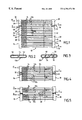
- FIG. 1 is a view in longitudinal section of a combined heat exchanger according to a first embodiment of the invention
- FIG. 2 is a view in section, on an enlarged scale, of a tube of the oil-cooler part
- FIG. 3 is a view in section, on an enlarged scale, of a tube of the condenser part
- FIG. 4 is a partial view in longitudinal section of a combined exchanger according to a second embodiment of the invention.
- FIG. 5 is a partial view in longitudinal section of an exchanger of the combined heat exchanger according to a third embodiment of the invention.
- the combined heat exchanger represented in FIG. 1 comprises a bank 10 , also called core, consisting of a multiplicity of tubes 12 extending parallel to each other and between which are arranged corrugated spacers 14 forming cooling fins.
- the ends of the tubes 12 open out, at one end, into a common manifold 16 and, at the other end, into another common manifold 18 .
- These two manifolds are of tubular configuration and extend parallel to each other.
- the various components of the heat exchanger that is to say the tubes 12 , the fins and the manifolds 16 and 18 are made of metal and assembled together by brazing.
- the bank is divided into two parts, namely a part A forming an oil cooler and consisting of tubes 12 a and a part B forming a condenser and consisting of tubes 12 b .
- the tubes 12 a are suitable for being traversed by oil H, such as the transmission oil for a motor-vehicle automatic gearbox.
- the tubes 12 b are suitable for being traversed by a cooling fluid R of a motor vehicle air-conditioning installation. It will be understood that these two fluids circulate in two different parts of the bank and are intended to be swept by the same airflow which sweeps over the bank 10 .
- the manifolds 16 and 18 include respective insulating partitions 20 and 22 for insulating the two fluids from one another.
- the partition 20 divides the manifold 16 into a compartment 24 for the oil (here placed in the upper part) and a compartment 26 for the cooling fluid (here placed in the lower part).
- the partition 22 divides the manifold 18 into a compartment 28 for the oil (here placed in the upper part) and a compartment 30 for the cooling fluid (here placed in the lower part).
- the oil to be cooled enters the compartment 24 through an entry pipe 32 , then flows in the tubes 12 a by parallel flow so as to reach the compartment 28 . It then leaves the compartment 28 through an outlet pipe 34 .
- the compartment 26 is itself divided into two parts, namely an upper part 36 and a lower part 38 , by a partition 40 .
- the compartment 30 of the manifold 18 is divided into two parts, namely an upper part 42 and a lower part 44 , by a partition 46 .
- the cooling fluid R enters the compartment 36 through a entry pipe 48 , flows in a part of the tubes 12 b so as to reach the compartment 42 , then flows in the opposite direction to reach the compartment 38 . Next, the cooling fluid reaches the compartment 44 , flowing again in the reverse direction, and leaves the heat exchanger through an outlet pipe 50 .
- the cooling fluid R flows alternately according to a three-pass mode.
- the tubes 12 a and 12 b are flat, multi-channel tubes, obtained by extrusion from an appropriate metal alloy, generally aluminum based.
- each tube 12 a (FIG. 2) includes two channels 52 separated by a partition 54
- each tube 12 b (FIG. 3) includes four channels 56 separated by three partitions 58 .
- the tubes 12 a and 12 b have the same outer cross-section, which allows standardization of manufacture, in the sense that the ends of the tubes are accommodated in identical holes formed in the manifolds 16 and 18 .
- the tubes 12 a and 12 b have hydraulic diameters DH of DHa and DHb respectively.
- the tubes 12 a and 12 b thus have specific characteristics making it possible to adapt them respectively to the cooling of the oil and to the cooling of the cooling fluid. Because the tubes 12 a have fewer channels (and thus fewer partitions) than the tubes 12 b , the hydraulic diameter of the tubes 12 a is increased, which makes it possible significantly to lower the loss of pressure head generated by the flowing of the oil in the tubes 12 a.
- the product DHa ⁇ DHb takes a value which falls in an interval defined by the following inequality:
- partitions 20 and 22 are provided which are particularly good insulators and which, advantageously, may be double partitions.
- FIG. 4 another embodiment of the invention is shown with means forming a thermal barrier between the tubes 12 a and the tubes 12 b.
- the bank 10 includes an inactive tube 12 i , also called “dead tube”, which is not traversed by any fluid and which opens out between a double partition 20 of the manifold 16 and a double partition 22 of the manifold 18 .
- the heat exchanger of FIG. 5 includes other means forming a thermal barrier.
- the bank is configured in such a way as to include a region 60 devoid of corrugated spacers, which extends between the parts A and B of the bank, that is to say between two adjacent tubes 12 a and 12 b belonging to these two parts A and B.
- the tubes 12 a and 12 b each have a length of 600 mm.
- the hydraulic diameter DHa of each of the tubes 12 a is equal to 1.6, while the hydraulic diameter DHb of each of the tubes 12 b is equal to 1.313, the product DHa ⁇ DHb thus being equal to 2.1.
Abstract
Description
Claims (20)
Applications Claiming Priority (2)
| Application Number | Priority Date | Filing Date | Title |
|---|---|---|---|
| FR9814655 | 1998-11-20 | ||
| FR9814655A FR2786259B1 (en) | 1998-11-20 | 1998-11-20 | COMBINED HEAT EXCHANGER, PARTICULARLY FOR A MOTOR VEHICLE |
Publications (1)
| Publication Number | Publication Date |
|---|---|
| US6394176B1 true US6394176B1 (en) | 2002-05-28 |
Family
ID=9533009
Family Applications (1)
| Application Number | Title | Priority Date | Filing Date |
|---|---|---|---|
| US09/442,281 Expired - Lifetime US6394176B1 (en) | 1998-11-20 | 1999-11-19 | Combined heat exchanger, particularly for a motor vehicle |
Country Status (7)
| Country | Link |
|---|---|
| US (1) | US6394176B1 (en) |
| EP (1) | EP1003005B1 (en) |
| AT (1) | ATE261573T1 (en) |
| BR (1) | BR9905655A (en) |
| DE (1) | DE69915431T2 (en) |
| ES (1) | ES2217672T3 (en) |
| FR (1) | FR2786259B1 (en) |
Cited By (76)
| Publication number | Priority date | Publication date | Assignee | Title |
|---|---|---|---|---|
| US20020040776A1 (en) * | 2000-10-11 | 2002-04-11 | Hiroshi Kokubunji | Heat exchanger |
| US20030209344A1 (en) * | 2002-05-07 | 2003-11-13 | Valeo Engine Cooling | Heat exchanger |
| US20030213587A1 (en) * | 2002-05-16 | 2003-11-20 | Takamitsu Mano | Heat exchanger with dual heat-exchanging portions |
| US20040216863A1 (en) * | 2003-04-30 | 2004-11-04 | Valeo, Inc. | Heat exchanger |
| US20040244953A1 (en) * | 2003-05-14 | 2004-12-09 | Naohisa Kamiyama | Compound type heat exchanger |
| US20040251015A1 (en) * | 2003-05-30 | 2004-12-16 | Pascal Bonnet | Heat exchanger having an improved baffle |
| US20040261983A1 (en) * | 2003-06-25 | 2004-12-30 | Zaiqian Hu | Heat exchanger |
| US20050006069A1 (en) * | 2003-05-14 | 2005-01-13 | Naohisa Kamiyama | Multi-function heat exchanger |
| US20050006080A1 (en) * | 2003-05-15 | 2005-01-13 | Naohisa Kamiyama | Compound type heat exchanger |
| US20050006081A1 (en) * | 2003-05-15 | 2005-01-13 | Naohisa Kamiyama | Compound type heat exchanger |
| US20050006068A1 (en) * | 2003-06-30 | 2005-01-13 | Sameer Desai | Heat exchanger |
| US20050056049A1 (en) * | 2003-09-16 | 2005-03-17 | Ryouichi Sanada | Heat exchanger module |
| GB2406164A (en) * | 2003-09-22 | 2005-03-23 | Visteon Global Tech Inc | Improved cooling performance of an automotive heat exchanger |
| US20050092475A1 (en) * | 2002-03-20 | 2005-05-05 | Behr Gmbh & Co. Kg | Heat exchanger and cooling system |
| US20050097457A1 (en) * | 1998-01-14 | 2005-05-05 | Microsoft Corporation | Extensible ordered information within a markup language document |
| US20050133207A1 (en) * | 2003-12-22 | 2005-06-23 | Modine Manufacturing Co. | Multi-fluid heat exchanger and method of making same |
| EP1531309A3 (en) * | 2003-11-13 | 2005-07-20 | Calsonic Kansei UK Limited | Condenser |
| US20050217839A1 (en) * | 2004-03-30 | 2005-10-06 | Papapanu Steven J | Integral primary and secondary heat exchanger |
| US20050236146A1 (en) * | 2003-12-11 | 2005-10-27 | Behr Gmbh & Co. Kg. | Assembly configuration for devices for exchanging heat |
| US20050257921A1 (en) * | 2004-05-21 | 2005-11-24 | Valeo, Inc. | Multi-type fins for multi-exchangers |
| US20060016584A1 (en) * | 2004-07-23 | 2006-01-26 | Homayoun Sanatgar | Fluid cooler assembly |
| WO2006014956A1 (en) * | 2004-07-31 | 2006-02-09 | Valeo, Inc. | Heat exchano'er having a double baffle |
| US20060060327A1 (en) * | 2004-09-23 | 2006-03-23 | Visteon Global Technologies, Inc. | Integrated condenser oil cooler with a receiver/dryer |
| US20060101850A1 (en) * | 2004-11-12 | 2006-05-18 | Carrier Corporation | Parallel flow evaporator with shaped manifolds |
| US20060102331A1 (en) * | 2004-11-12 | 2006-05-18 | Carrier Corporation | Parallel flow evaporator with spiral inlet manifold |
| US20060101849A1 (en) * | 2004-11-12 | 2006-05-18 | Carrier Corporation | Parallel flow evaporator with variable channel insertion depth |
| US20060113068A1 (en) * | 2004-11-30 | 2006-06-01 | Valeo, Inc. | Multi fluid heat exchanger assembly |
| US20060137368A1 (en) * | 2004-12-27 | 2006-06-29 | Carrier Corporation | Visual display of temperature differences for refrigerant charge indication |
| US20060207754A1 (en) * | 2005-03-18 | 2006-09-21 | Christopher Wisniewski | Variable oil cooler tube size for combo cooler |
| US20060254752A1 (en) * | 2005-04-06 | 2006-11-16 | Matsushita Electric Industrial Co., Ltd. | Radiator and heatsink apparatus having the radiator |
| US20060278365A1 (en) * | 2004-06-10 | 2006-12-14 | Ryouichi Sanada | Cooling system used for hybrid-powered automobile |
| US20070044953A1 (en) * | 2005-08-31 | 2007-03-01 | Valeo, Inc. | Heat exchanger |
| US20070144803A1 (en) * | 2005-12-24 | 2007-06-28 | Dr. Ing. H.C.F. Porsche Ag | Heat exchanger device |
| US20070187077A1 (en) * | 2006-02-13 | 2007-08-16 | Daebok Kwon | Integral-type heat exchanger |
| US20070199685A1 (en) * | 2006-02-28 | 2007-08-30 | Valeo, Inc. | Two-fold combo-cooler |
| US20080023182A1 (en) * | 2006-07-25 | 2008-01-31 | Henry Earl Beamer | Dual mode heat exchanger assembly |
| US20080047687A1 (en) * | 2006-08-22 | 2008-02-28 | Frank Joseph Leitch | Combination heat exchanger having an improved end tank assembly |
| US20080093051A1 (en) * | 2005-02-02 | 2008-04-24 | Arturo Rios | Tube Insert and Bi-Flow Arrangement for a Header of a Heat Pump |
| US20080104975A1 (en) * | 2005-02-02 | 2008-05-08 | Carrier Corporation | Liquid-Vapor Separator For A Minichannel Heat Exchanger |
| US20080115528A1 (en) * | 2006-11-17 | 2008-05-22 | Denso Corporation | Cooling module |
| US7377126B2 (en) | 2004-07-14 | 2008-05-27 | Carrier Corporation | Refrigeration system |
| CN100395444C (en) * | 2004-08-26 | 2008-06-18 | 株式会社电装 | Intercooler |
| US20080141709A1 (en) * | 2006-11-22 | 2008-06-19 | Johnson Controls Technology Company | Multi-Block Circuit Multichannel Heat Exchanger |
| US20080142203A1 (en) * | 2006-11-22 | 2008-06-19 | Johnson Controls Technology Company | Multichannel Heat Exchanger With Dissimilar Multichannel Tubes |
| US7398819B2 (en) | 2004-11-12 | 2008-07-15 | Carrier Corporation | Minichannel heat exchanger with restrictive inserts |
| US20090020081A1 (en) * | 2007-07-16 | 2009-01-22 | Gm Global Technology Operations, Inc. | Integrated Vehicle Cooling System |
| US20090038778A1 (en) * | 2005-12-28 | 2009-02-12 | Wabtec Holding Corp. | Multi-fluid heat exchanger arrangement |
| US20090073658A1 (en) * | 2007-09-13 | 2009-03-19 | Balcerak John A | Modular Liquid Cooling System |
| US20090078399A1 (en) * | 2007-09-21 | 2009-03-26 | Denso Corporation | Combined heat exchanger |
| US20100071675A1 (en) * | 2007-03-16 | 2010-03-25 | Peter Geskes | Flow channel, heat exchanger, exhaust gas recirculation system, charge air supply system, use of a heat exchanger |
| US20100147498A1 (en) * | 2008-12-15 | 2010-06-17 | Delphi Technologies, Inc. | Heat exchanger assembly |
| US20100212874A1 (en) * | 2007-06-20 | 2010-08-26 | Halla Climate Control Corp. | Cooling system for a vehicle |
| WO2010105170A2 (en) * | 2009-03-13 | 2010-09-16 | Carrier Corporation | Manifold assembly for distributing a fluid to a heat exchanger |
| CN101600919B (en) * | 2006-11-22 | 2011-06-01 | 约翰逊控制技术公司 | Multichannel heat exchanger with dissimilar multichannel tubes |
| US20110174301A1 (en) * | 2010-01-20 | 2011-07-21 | Carrier Corporation | Primary Heat Exchanger Design for Condensing Gas Furnace |
| US20120011867A1 (en) * | 2009-04-03 | 2012-01-19 | Carrier Corporation | Multi-circuit heat exchanger |
| DE102012009357A1 (en) | 2012-05-10 | 2012-11-29 | Daimler Ag | Heat exchanger i.e. radiator, for use in e.g. low temperature cooling circuit to cool vehicle's internal combustion engine, has fluidically separate sections together with coolant channels forming fluidically separate partial heat exchanger |
| EP2375208B1 (en) * | 2010-03-31 | 2012-12-05 | VALEO AUTOSYSTEMY Sp. Z. o.o. | Improved heat exchanger |
| US8397797B2 (en) | 2010-03-31 | 2013-03-19 | Denso International America, Inc. | Low thermal strain multi-cooler |
| US20130220584A1 (en) * | 2010-12-01 | 2013-08-29 | Sharp Kabushiki Kaisha | Heat exchanger, and all-in-one air conditioner equipped therewith |
| WO2014076874A1 (en) * | 2012-11-13 | 2014-05-22 | 株式会社デンソー | Heat exchanger |
| CN104567469A (en) * | 2014-12-26 | 2015-04-29 | 无锡久盛换热器有限公司 | Compact oil-air cooler |
| EP2887000A2 (en) | 2013-12-20 | 2015-06-24 | Valeo North America, Inc. | Combo-cooler |
| US20150241130A1 (en) * | 2012-10-23 | 2015-08-27 | Kiturami Boiler Co., Ltd. | Condensation heat exchanger having dummy pipe |
| US20150298538A1 (en) * | 2014-04-18 | 2015-10-22 | Ford Global Technologies, Llc | Multiple zoned radiator |
| US20170328637A1 (en) * | 2016-05-13 | 2017-11-16 | Denso Thermal Systems S.P.A. | Heat exchanger with dummy tubes |
| US20170370658A1 (en) * | 2016-06-23 | 2017-12-28 | Modine Manufacturing Company | Heat Exchanger and Header for the Same |
| US20180058765A1 (en) * | 2016-08-26 | 2018-03-01 | Autokühler GmbH & Co., Kg | Heat exchanger |
| US20180149089A1 (en) * | 2016-11-30 | 2018-05-31 | Hamilton Sundstrand Corporation | Method for reducing thermally induced stresses in a heat exchanger |
| US10161686B2 (en) | 2009-04-13 | 2018-12-25 | Carrier Corporation | Microchanel heat exchanger evaporator |
| US20190086152A1 (en) * | 2017-09-18 | 2019-03-21 | Ingersoll-Rand Company | Evaporative cooling of a heat exchanger in a compressor system |
| CN109579576A (en) * | 2018-11-27 | 2019-04-05 | 爱赫德换热系统(无锡)有限公司 | A kind of oil gas combines the heat exchanger of heat exchange |
| EP3139122B1 (en) * | 2015-09-07 | 2020-04-22 | Lg Electronics Inc. | Micro channel type heat exchanger |
| USD892878S1 (en) * | 2019-02-28 | 2020-08-11 | Resource International Inc. | Transmission cooler for automotive applications |
| USD892877S1 (en) * | 2019-02-28 | 2020-08-11 | Resource International Inc. | Transmission cooler for automotive applications |
| EP3809081A1 (en) * | 2019-10-18 | 2021-04-21 | Valeo Autosystemy SP. Z.O.O. | A heat exchanger |
Families Citing this family (6)
| Publication number | Priority date | Publication date | Assignee | Title |
|---|---|---|---|---|
| DE10158436A1 (en) * | 2001-11-29 | 2003-06-12 | Behr Gmbh & Co | heat exchangers |
| DE102006017434B4 (en) | 2005-08-04 | 2020-03-12 | Hanon Systems | Multi-flow heat exchanger |
| DE102006005245A1 (en) * | 2006-02-02 | 2007-08-09 | Behr Gmbh & Co. Kg | Heat exchanger for a refrigeration cycle |
| WO2008064247A1 (en) * | 2006-11-22 | 2008-05-29 | Johnson Controls Technology Company | Multi-function multichannel heat exchanger |
| WO2011005986A2 (en) * | 2009-07-10 | 2011-01-13 | Johnson Controls Technology Company | Multichannel heat exchanger with differing fin spacing |
| DE102010043243A1 (en) * | 2010-11-03 | 2012-05-03 | BSH Bosch und Siemens Hausgeräte GmbH | heat exchangers |
Citations (20)
| Publication number | Priority date | Publication date | Assignee | Title |
|---|---|---|---|---|
| US2037845A (en) * | 1935-08-12 | 1936-04-21 | Young Radiator Co | Radiator |
| US2264820A (en) * | 1939-05-17 | 1941-12-02 | Fred M Young | Combination oil and water cooler |
| US2505790A (en) * | 1946-07-24 | 1950-05-02 | Perfex Corp | Combination radiator and oil cooler |
| DE1088027B (en) * | 1958-07-04 | 1960-09-01 | Zieren Chemiebau Gmbh Dr A | Process and device for the separation of reaction products which are solid at room temperature from gas mixtures |
| US3447596A (en) * | 1967-07-10 | 1969-06-03 | Carl N Hughes | Automobile air-conditioning system |
| US4651816A (en) * | 1986-03-19 | 1987-03-24 | Modine Manufacturing Company | Heat exchanger module for a vehicle or the like |
| EP0361358A1 (en) | 1988-09-30 | 1990-04-04 | FIAT AUTO S.p.A. | Integral water/oil radiator, particularly for vehicles |
| US4947931A (en) * | 1989-12-28 | 1990-08-14 | Vitacco Richard L | Plastic vehicular radiator-condenser with metal cooling inserts |
| US4998580A (en) * | 1985-10-02 | 1991-03-12 | Modine Manufacturing Company | Condenser with small hydraulic diameter flow path |
| US5186244A (en) | 1992-04-08 | 1993-02-16 | General Motors Corporation | Tube design for integral radiator/condenser |
| GB2262600A (en) * | 1991-12-19 | 1993-06-23 | Behr Gmbh & Co | Modular unit with multiple heat exchanger for motor vehicles |
| US5303770A (en) * | 1993-06-04 | 1994-04-19 | Dierbeck Robert F | Modular heat exchanger |
| US5372188A (en) * | 1985-10-02 | 1994-12-13 | Modine Manufacturing Co. | Heat exchanger for a refrigerant system |
| DE9401035U1 (en) | 1994-01-22 | 1995-05-24 | Behr Gmbh & Co | Cooling device for a motor vehicle |
| US5526873A (en) * | 1989-07-19 | 1996-06-18 | Valeo Thermique Moteur | Heat exchanger apparatus for a plurality of cooling circuits using the same coolant |
| EP0773419A2 (en) | 1995-11-13 | 1997-05-14 | Denso Corporation | Heat exchanger |
| US5743328A (en) | 1989-08-23 | 1998-04-28 | Showa Aluminum Corporation | Duplex heat exchanger |
| US5894885A (en) * | 1996-11-04 | 1999-04-20 | Valeo Thermique Moteur | Condenser having a simplified assembly for use in an air conditioning circuit for a vehicle |
| US6035927A (en) * | 1997-07-09 | 2000-03-14 | Behr Gmbh & Co. | Tube/fin block for a heat exchanger and manufacturing process therefor |
| US6062303A (en) * | 1997-09-26 | 2000-05-16 | Halla Climate Control Corp. | Multiflow type condenser for an air conditioner |
Family Cites Families (1)
| Publication number | Priority date | Publication date | Assignee | Title |
|---|---|---|---|---|
| JPS61167202A (en) | 1985-01-18 | 1986-07-28 | Murata Mfg Co Ltd | Dielectric resonator |
-
1998
- 1998-11-20 FR FR9814655A patent/FR2786259B1/en not_active Expired - Fee Related
-
1999
- 1999-11-10 ES ES99122374T patent/ES2217672T3/en not_active Expired - Lifetime
- 1999-11-10 AT AT99122374T patent/ATE261573T1/en not_active IP Right Cessation
- 1999-11-10 DE DE69915431T patent/DE69915431T2/en not_active Revoked
- 1999-11-10 EP EP99122374A patent/EP1003005B1/en not_active Revoked
- 1999-11-18 BR BR9905655-0A patent/BR9905655A/en not_active IP Right Cessation
- 1999-11-19 US US09/442,281 patent/US6394176B1/en not_active Expired - Lifetime
Patent Citations (22)
| Publication number | Priority date | Publication date | Assignee | Title |
|---|---|---|---|---|
| US2037845A (en) * | 1935-08-12 | 1936-04-21 | Young Radiator Co | Radiator |
| US2264820A (en) * | 1939-05-17 | 1941-12-02 | Fred M Young | Combination oil and water cooler |
| US2505790A (en) * | 1946-07-24 | 1950-05-02 | Perfex Corp | Combination radiator and oil cooler |
| DE1088027B (en) * | 1958-07-04 | 1960-09-01 | Zieren Chemiebau Gmbh Dr A | Process and device for the separation of reaction products which are solid at room temperature from gas mixtures |
| US3447596A (en) * | 1967-07-10 | 1969-06-03 | Carl N Hughes | Automobile air-conditioning system |
| US4998580A (en) * | 1985-10-02 | 1991-03-12 | Modine Manufacturing Company | Condenser with small hydraulic diameter flow path |
| US5341870A (en) * | 1985-10-02 | 1994-08-30 | Modine Manufacturing Company | Evaporator or evaporator/condenser |
| US5372188A (en) * | 1985-10-02 | 1994-12-13 | Modine Manufacturing Co. | Heat exchanger for a refrigerant system |
| US4651816A (en) * | 1986-03-19 | 1987-03-24 | Modine Manufacturing Company | Heat exchanger module for a vehicle or the like |
| EP0361358A1 (en) | 1988-09-30 | 1990-04-04 | FIAT AUTO S.p.A. | Integral water/oil radiator, particularly for vehicles |
| US4923001A (en) * | 1988-09-30 | 1990-05-08 | Fiat Auto S.P.A. | Integral water/oil radiator, particularly for vehicles |
| US5526873A (en) * | 1989-07-19 | 1996-06-18 | Valeo Thermique Moteur | Heat exchanger apparatus for a plurality of cooling circuits using the same coolant |
| US5743328A (en) | 1989-08-23 | 1998-04-28 | Showa Aluminum Corporation | Duplex heat exchanger |
| US4947931A (en) * | 1989-12-28 | 1990-08-14 | Vitacco Richard L | Plastic vehicular radiator-condenser with metal cooling inserts |
| GB2262600A (en) * | 1991-12-19 | 1993-06-23 | Behr Gmbh & Co | Modular unit with multiple heat exchanger for motor vehicles |
| US5186244A (en) | 1992-04-08 | 1993-02-16 | General Motors Corporation | Tube design for integral radiator/condenser |
| US5303770A (en) * | 1993-06-04 | 1994-04-19 | Dierbeck Robert F | Modular heat exchanger |
| DE9401035U1 (en) | 1994-01-22 | 1995-05-24 | Behr Gmbh & Co | Cooling device for a motor vehicle |
| EP0773419A2 (en) | 1995-11-13 | 1997-05-14 | Denso Corporation | Heat exchanger |
| US5894885A (en) * | 1996-11-04 | 1999-04-20 | Valeo Thermique Moteur | Condenser having a simplified assembly for use in an air conditioning circuit for a vehicle |
| US6035927A (en) * | 1997-07-09 | 2000-03-14 | Behr Gmbh & Co. | Tube/fin block for a heat exchanger and manufacturing process therefor |
| US6062303A (en) * | 1997-09-26 | 2000-05-16 | Halla Climate Control Corp. | Multiflow type condenser for an air conditioner |
Cited By (146)
| Publication number | Priority date | Publication date | Assignee | Title |
|---|---|---|---|---|
| US20050097457A1 (en) * | 1998-01-14 | 2005-05-05 | Microsoft Corporation | Extensible ordered information within a markup language document |
| US6938675B2 (en) * | 2000-10-11 | 2005-09-06 | Denso Corporation | Heat exchanger |
| US20020040776A1 (en) * | 2000-10-11 | 2002-04-11 | Hiroshi Kokubunji | Heat exchanger |
| US20050092475A1 (en) * | 2002-03-20 | 2005-05-05 | Behr Gmbh & Co. Kg | Heat exchanger and cooling system |
| US20050161203A1 (en) * | 2002-05-07 | 2005-07-28 | Valeo, Inc | Heat exchanger |
| US20030209344A1 (en) * | 2002-05-07 | 2003-11-13 | Valeo Engine Cooling | Heat exchanger |
| US6793012B2 (en) * | 2002-05-07 | 2004-09-21 | Valeo, Inc | Heat exchanger |
| US20040200604A1 (en) * | 2002-05-07 | 2004-10-14 | Valeo, Inc | Heat exchanger |
| US7059393B2 (en) | 2002-05-07 | 2006-06-13 | Valeo, Inc. | Heat exchanger |
| US6942023B2 (en) * | 2002-05-07 | 2005-09-13 | Valeo, Inc. | Heat exchanger |
| US20030213587A1 (en) * | 2002-05-16 | 2003-11-20 | Takamitsu Mano | Heat exchanger with dual heat-exchanging portions |
| US6883600B2 (en) * | 2002-05-16 | 2005-04-26 | Denso Corporation | Heat exchanger with dual heat-exchanging portions |
| US20040216863A1 (en) * | 2003-04-30 | 2004-11-04 | Valeo, Inc. | Heat exchanger |
| US20050016716A1 (en) * | 2003-04-30 | 2005-01-27 | Valeo, Inc. | Heat exchanger |
| US7337832B2 (en) | 2003-04-30 | 2008-03-04 | Valeo, Inc. | Heat exchanger |
| WO2004099695A1 (en) * | 2003-04-30 | 2004-11-18 | Valeo Inc. | Heat exchanger |
| US20050006069A1 (en) * | 2003-05-14 | 2005-01-13 | Naohisa Kamiyama | Multi-function heat exchanger |
| US7077193B2 (en) * | 2003-05-14 | 2006-07-18 | Calsonic Kansei Corporation | Compound type heat exchanger |
| US7051795B2 (en) * | 2003-05-14 | 2006-05-30 | Calsonic Kansei Corporation | Multi-function heat exchanger |
| US20040244953A1 (en) * | 2003-05-14 | 2004-12-09 | Naohisa Kamiyama | Compound type heat exchanger |
| US20050006080A1 (en) * | 2003-05-15 | 2005-01-13 | Naohisa Kamiyama | Compound type heat exchanger |
| EP1477759A3 (en) * | 2003-05-15 | 2008-02-13 | Calsonic Kansei Corporation | Compound type heat exchanger |
| US7025128B2 (en) * | 2003-05-15 | 2006-04-11 | Calsonic Kansei Corporation | Compound type heat exchanger |
| US7036571B2 (en) * | 2003-05-15 | 2006-05-02 | Calsonic Kansei Corporation | Compound type heat exchanger |
| US20050006081A1 (en) * | 2003-05-15 | 2005-01-13 | Naohisa Kamiyama | Compound type heat exchanger |
| EP1477760A3 (en) * | 2003-05-15 | 2008-03-12 | Calsonic Kansei Corporation | Compound type heat exchanger |
| US6942014B2 (en) * | 2003-05-30 | 2005-09-13 | Valeo, Inc. | Heat exchanger having an improved baffle |
| US20040251015A1 (en) * | 2003-05-30 | 2004-12-16 | Pascal Bonnet | Heat exchanger having an improved baffle |
| WO2005001365A1 (en) * | 2003-05-30 | 2005-01-06 | Valeo Inc | Heat exchanger having an improved baffle |
| US6904963B2 (en) * | 2003-06-25 | 2005-06-14 | Valeo, Inc. | Heat exchanger |
| US20040261983A1 (en) * | 2003-06-25 | 2004-12-30 | Zaiqian Hu | Heat exchanger |
| WO2005003669A3 (en) * | 2003-06-25 | 2005-03-03 | Valeo Inc | Heat exchanger |
| US7527087B2 (en) | 2003-06-30 | 2009-05-05 | Valeo, Inc. | Heat exchanger |
| US20050006068A1 (en) * | 2003-06-30 | 2005-01-13 | Sameer Desai | Heat exchanger |
| US7591148B2 (en) | 2003-09-16 | 2009-09-22 | Denso Corporation | Vehicular heat exchanger module |
| US7669437B2 (en) | 2003-09-16 | 2010-03-02 | Denso Corporation | Heat exchanger module |
| US20050056049A1 (en) * | 2003-09-16 | 2005-03-17 | Ryouichi Sanada | Heat exchanger module |
| US20080282730A1 (en) * | 2003-09-16 | 2008-11-20 | Ryouichi Sanada | Heat exchanger module |
| KR100893169B1 (en) * | 2003-09-16 | 2009-04-17 | 가부시키가이샤 덴소 | Heat exchanger module |
| US20050061488A1 (en) * | 2003-09-22 | 2005-03-24 | Visteon Global Technologies, Inc. | Automotive heat exchanger |
| GB2406164A (en) * | 2003-09-22 | 2005-03-23 | Visteon Global Tech Inc | Improved cooling performance of an automotive heat exchanger |
| US7073570B2 (en) | 2003-09-22 | 2006-07-11 | Visteon Global Technologies, Inc. | Automotive heat exchanger |
| US20050061489A1 (en) * | 2003-09-22 | 2005-03-24 | Visteon Global Technologies, Inc. | Integrated multi-function return tube for combo heat exchangers |
| GB2406164B (en) * | 2003-09-22 | 2005-09-07 | Visteon Global Tech Inc | Automotive heat exchanger |
| EP1531309A3 (en) * | 2003-11-13 | 2005-07-20 | Calsonic Kansei UK Limited | Condenser |
| CN1910420B (en) * | 2003-12-11 | 2010-05-12 | 贝尔两合公司 | Heat-exchanging devices system |
| US20050236146A1 (en) * | 2003-12-11 | 2005-10-27 | Behr Gmbh & Co. Kg. | Assembly configuration for devices for exchanging heat |
| US7096932B2 (en) * | 2003-12-22 | 2006-08-29 | Modine Manufacturing Company | Multi-fluid heat exchanger and method of making same |
| US20050133207A1 (en) * | 2003-12-22 | 2005-06-23 | Modine Manufacturing Co. | Multi-fluid heat exchanger and method of making same |
| US20050217839A1 (en) * | 2004-03-30 | 2005-10-06 | Papapanu Steven J | Integral primary and secondary heat exchanger |
| US20050257921A1 (en) * | 2004-05-21 | 2005-11-24 | Valeo, Inc. | Multi-type fins for multi-exchangers |
| US7506683B2 (en) * | 2004-05-21 | 2009-03-24 | Valeo, Inc. | Multi-type fins for multi-exchangers |
| US20060278365A1 (en) * | 2004-06-10 | 2006-12-14 | Ryouichi Sanada | Cooling system used for hybrid-powered automobile |
| US7377126B2 (en) | 2004-07-14 | 2008-05-27 | Carrier Corporation | Refrigeration system |
| US20060016584A1 (en) * | 2004-07-23 | 2006-01-26 | Homayoun Sanatgar | Fluid cooler assembly |
| US7013962B2 (en) * | 2004-07-23 | 2006-03-21 | Homayoun Sanatgar | High pressure fluid cooler |
| WO2006014956A1 (en) * | 2004-07-31 | 2006-02-09 | Valeo, Inc. | Heat exchano'er having a double baffle |
| CN100395444C (en) * | 2004-08-26 | 2008-06-18 | 株式会社电装 | Intercooler |
| US7073571B2 (en) | 2004-09-23 | 2006-07-11 | Visteon Global Technologies, Inc. | Integrated condenser oil cooler with a receiver/dryer |
| US20060060327A1 (en) * | 2004-09-23 | 2006-03-23 | Visteon Global Technologies, Inc. | Integrated condenser oil cooler with a receiver/dryer |
| DE102005046346B4 (en) * | 2004-09-23 | 2020-03-19 | Hanon Systems | Integrated fluid cooler and fluid condenser with an intermediate container / dryer |
| US7398819B2 (en) | 2004-11-12 | 2008-07-15 | Carrier Corporation | Minichannel heat exchanger with restrictive inserts |
| US8302673B2 (en) | 2004-11-12 | 2012-11-06 | Carrier Corporation | Parallel flow evaporator with spiral inlet manifold |
| US20100071392A1 (en) * | 2004-11-12 | 2010-03-25 | Carrier Corporation | Parallel flow evaporator with shaped manifolds |
| US20100218924A1 (en) * | 2004-11-12 | 2010-09-02 | Carrier Corporation | Parallel flow evaporator with spiral inlet manifold |
| US20060101849A1 (en) * | 2004-11-12 | 2006-05-18 | Carrier Corporation | Parallel flow evaporator with variable channel insertion depth |
| US7806171B2 (en) | 2004-11-12 | 2010-10-05 | Carrier Corporation | Parallel flow evaporator with spiral inlet manifold |
| US20060101850A1 (en) * | 2004-11-12 | 2006-05-18 | Carrier Corporation | Parallel flow evaporator with shaped manifolds |
| US20060102331A1 (en) * | 2004-11-12 | 2006-05-18 | Carrier Corporation | Parallel flow evaporator with spiral inlet manifold |
| US20060113068A1 (en) * | 2004-11-30 | 2006-06-01 | Valeo, Inc. | Multi fluid heat exchanger assembly |
| US20060137368A1 (en) * | 2004-12-27 | 2006-06-29 | Carrier Corporation | Visual display of temperature differences for refrigerant charge indication |
| US20080093051A1 (en) * | 2005-02-02 | 2008-04-24 | Arturo Rios | Tube Insert and Bi-Flow Arrangement for a Header of a Heat Pump |
| US20080104975A1 (en) * | 2005-02-02 | 2008-05-08 | Carrier Corporation | Liquid-Vapor Separator For A Minichannel Heat Exchanger |
| US8113270B2 (en) | 2005-02-02 | 2012-02-14 | Carrier Corporation | Tube insert and bi-flow arrangement for a header of a heat pump |
| US20060207754A1 (en) * | 2005-03-18 | 2006-09-21 | Christopher Wisniewski | Variable oil cooler tube size for combo cooler |
| US7143822B2 (en) | 2005-03-18 | 2006-12-05 | Denso International America, Inc. | Variable oil cooler tube size for combo cooler |
| US20060254752A1 (en) * | 2005-04-06 | 2006-11-16 | Matsushita Electric Industrial Co., Ltd. | Radiator and heatsink apparatus having the radiator |
| US20070044953A1 (en) * | 2005-08-31 | 2007-03-01 | Valeo, Inc. | Heat exchanger |
| US20070144803A1 (en) * | 2005-12-24 | 2007-06-28 | Dr. Ing. H.C.F. Porsche Ag | Heat exchanger device |
| US10113801B2 (en) | 2005-12-28 | 2018-10-30 | Wabtec Holding Corp. | Multi-fluid heat exchanger arrangement |
| US20090038778A1 (en) * | 2005-12-28 | 2009-02-12 | Wabtec Holding Corp. | Multi-fluid heat exchanger arrangement |
| US7490659B2 (en) * | 2006-02-13 | 2009-02-17 | Halla Climate Control Corporation | Integral-type heat exchanger |
| US20070187077A1 (en) * | 2006-02-13 | 2007-08-16 | Daebok Kwon | Integral-type heat exchanger |
| US20070199685A1 (en) * | 2006-02-28 | 2007-08-30 | Valeo, Inc. | Two-fold combo-cooler |
| US20080023182A1 (en) * | 2006-07-25 | 2008-01-31 | Henry Earl Beamer | Dual mode heat exchanger assembly |
| US20080047687A1 (en) * | 2006-08-22 | 2008-02-28 | Frank Joseph Leitch | Combination heat exchanger having an improved end tank assembly |
| US7779893B2 (en) | 2006-08-22 | 2010-08-24 | Delphi Technologies, Inc. | Combination heat exchanger having an improved end tank assembly |
| US20080115528A1 (en) * | 2006-11-17 | 2008-05-22 | Denso Corporation | Cooling module |
| CN101600929B (en) * | 2006-11-22 | 2012-05-09 | 约翰逊控制技术公司 | Multichannel heat exchanger with dissimilar tube spacing |
| CN101600919B (en) * | 2006-11-22 | 2011-06-01 | 约翰逊控制技术公司 | Multichannel heat exchanger with dissimilar multichannel tubes |
| US7757753B2 (en) * | 2006-11-22 | 2010-07-20 | Johnson Controls Technology Company | Multichannel heat exchanger with dissimilar multichannel tubes |
| US20080142203A1 (en) * | 2006-11-22 | 2008-06-19 | Johnson Controls Technology Company | Multichannel Heat Exchanger With Dissimilar Multichannel Tubes |
| US20080141709A1 (en) * | 2006-11-22 | 2008-06-19 | Johnson Controls Technology Company | Multi-Block Circuit Multichannel Heat Exchanger |
| US7980094B2 (en) | 2006-11-22 | 2011-07-19 | Johnson Controls Technology Company | Multichannel heat exchanger with dissimilar tube spacing |
| US20090288440A1 (en) * | 2006-11-22 | 2009-11-26 | Johnson Controls Technology Company | Multichannel Heat Exchanger with Dissimilar Tube Spacing |
| US20100071675A1 (en) * | 2007-03-16 | 2010-03-25 | Peter Geskes | Flow channel, heat exchanger, exhaust gas recirculation system, charge air supply system, use of a heat exchanger |
| US7866305B2 (en) * | 2007-03-16 | 2011-01-11 | Behr Gmbh & Co. Kg | Flow channel, heat exchanger, exhaust gas recirculation system, charge air supply system, use of a heat exchanger |
| US8276651B2 (en) | 2007-06-20 | 2012-10-02 | Halla Climate Control Corp. | Cooling system for a vehicle |
| US20100212874A1 (en) * | 2007-06-20 | 2010-08-26 | Halla Climate Control Corp. | Cooling system for a vehicle |
| US7669558B2 (en) * | 2007-07-16 | 2010-03-02 | Gm Global Technology Operations, Inc. | Integrated vehicle cooling system |
| US20090020081A1 (en) * | 2007-07-16 | 2009-01-22 | Gm Global Technology Operations, Inc. | Integrated Vehicle Cooling System |
| US20090073658A1 (en) * | 2007-09-13 | 2009-03-19 | Balcerak John A | Modular Liquid Cooling System |
| US9099237B2 (en) | 2007-09-13 | 2015-08-04 | Rockwell Automation Technologies, Inc. | Modular liquid cooling system |
| US8081462B2 (en) * | 2007-09-13 | 2011-12-20 | Rockwell Automation Technologies, Inc. | Modular liquid cooling system |
| US20090078399A1 (en) * | 2007-09-21 | 2009-03-26 | Denso Corporation | Combined heat exchanger |
| US8196646B2 (en) | 2008-12-15 | 2012-06-12 | Delphi Technologies, Inc. | Heat exchanger assembly |
| US20100147498A1 (en) * | 2008-12-15 | 2010-06-17 | Delphi Technologies, Inc. | Heat exchanger assembly |
| WO2010105170A3 (en) * | 2009-03-13 | 2011-02-03 | Carrier Corporation | Manifold assembly for distributing a fluid to a heat exchanger |
| CN102348953B (en) * | 2009-03-13 | 2014-08-27 | 开利公司 | Manifold assembly for distributing a fluid to a heat exchanger |
| CN102348953A (en) * | 2009-03-13 | 2012-02-08 | 开利公司 | Manifold assembly for distributing a fluid to a heat exchanger |
| US9562722B2 (en) | 2009-03-13 | 2017-02-07 | Carrier Corporation | Manifold assembly for distributing a fluid to a heat exchanger |
| WO2010105170A2 (en) * | 2009-03-13 | 2010-09-16 | Carrier Corporation | Manifold assembly for distributing a fluid to a heat exchanger |
| US20120011867A1 (en) * | 2009-04-03 | 2012-01-19 | Carrier Corporation | Multi-circuit heat exchanger |
| US10161686B2 (en) | 2009-04-13 | 2018-12-25 | Carrier Corporation | Microchanel heat exchanger evaporator |
| US8826901B2 (en) | 2010-01-20 | 2014-09-09 | Carrier Corporation | Primary heat exchanger design for condensing gas furnace |
| US20110174301A1 (en) * | 2010-01-20 | 2011-07-21 | Carrier Corporation | Primary Heat Exchanger Design for Condensing Gas Furnace |
| US8397797B2 (en) | 2010-03-31 | 2013-03-19 | Denso International America, Inc. | Low thermal strain multi-cooler |
| EP2375208B1 (en) * | 2010-03-31 | 2012-12-05 | VALEO AUTOSYSTEMY Sp. Z. o.o. | Improved heat exchanger |
| US20130220584A1 (en) * | 2010-12-01 | 2013-08-29 | Sharp Kabushiki Kaisha | Heat exchanger, and all-in-one air conditioner equipped therewith |
| DE102012009357A1 (en) | 2012-05-10 | 2012-11-29 | Daimler Ag | Heat exchanger i.e. radiator, for use in e.g. low temperature cooling circuit to cool vehicle's internal combustion engine, has fluidically separate sections together with coolant channels forming fluidically separate partial heat exchanger |
| US20150241130A1 (en) * | 2012-10-23 | 2015-08-27 | Kiturami Boiler Co., Ltd. | Condensation heat exchanger having dummy pipe |
| US10222126B2 (en) * | 2012-10-23 | 2019-03-05 | Kiturami Boiler Co., Ltd. | Condensation heat exchanger having dummy pipe |
| CN104781627A (en) * | 2012-11-13 | 2015-07-15 | 株式会社电装 | Heat exchanger |
| CN104781627B (en) * | 2012-11-13 | 2018-02-09 | 株式会社电装 | Heat exchanger |
| JP2014098498A (en) * | 2012-11-13 | 2014-05-29 | Denso Corp | Heat exchanger |
| WO2014076874A1 (en) * | 2012-11-13 | 2014-05-22 | 株式会社デンソー | Heat exchanger |
| EP2887000A2 (en) | 2013-12-20 | 2015-06-24 | Valeo North America, Inc. | Combo-cooler |
| US20150298538A1 (en) * | 2014-04-18 | 2015-10-22 | Ford Global Technologies, Llc | Multiple zoned radiator |
| CN105015320B (en) * | 2014-04-18 | 2020-08-11 | 福特全球技术公司 | Multi-zone heat sink |
| US10286774B2 (en) * | 2014-04-18 | 2019-05-14 | Ford Global Technologies, Llc | Multiple zoned radiator |
| CN105015320A (en) * | 2014-04-18 | 2015-11-04 | 福特全球技术公司 | Multiple zoned radiator |
| CN104567469A (en) * | 2014-12-26 | 2015-04-29 | 无锡久盛换热器有限公司 | Compact oil-air cooler |
| US10670343B2 (en) | 2015-09-07 | 2020-06-02 | Lg Electronics Inc. | Micro channel type heat exchanger |
| EP3139122B1 (en) * | 2015-09-07 | 2020-04-22 | Lg Electronics Inc. | Micro channel type heat exchanger |
| US20170328637A1 (en) * | 2016-05-13 | 2017-11-16 | Denso Thermal Systems S.P.A. | Heat exchanger with dummy tubes |
| US20170370658A1 (en) * | 2016-06-23 | 2017-12-28 | Modine Manufacturing Company | Heat Exchanger and Header for the Same |
| US11460256B2 (en) | 2016-06-23 | 2022-10-04 | Modine Manufacturing Company | Heat exchanger header |
| US20180058765A1 (en) * | 2016-08-26 | 2018-03-01 | Autokühler GmbH & Co., Kg | Heat exchanger |
| US10487742B2 (en) * | 2016-11-30 | 2019-11-26 | Hamilton Sundstrand Corporation | Method for reducing thermally induced stresses in a heat exchanger |
| US20180149089A1 (en) * | 2016-11-30 | 2018-05-31 | Hamilton Sundstrand Corporation | Method for reducing thermally induced stresses in a heat exchanger |
| US20190086152A1 (en) * | 2017-09-18 | 2019-03-21 | Ingersoll-Rand Company | Evaporative cooling of a heat exchanger in a compressor system |
| CN109579576A (en) * | 2018-11-27 | 2019-04-05 | 爱赫德换热系统(无锡)有限公司 | A kind of oil gas combines the heat exchanger of heat exchange |
| USD892878S1 (en) * | 2019-02-28 | 2020-08-11 | Resource International Inc. | Transmission cooler for automotive applications |
| USD892877S1 (en) * | 2019-02-28 | 2020-08-11 | Resource International Inc. | Transmission cooler for automotive applications |
| EP3809081A1 (en) * | 2019-10-18 | 2021-04-21 | Valeo Autosystemy SP. Z.O.O. | A heat exchanger |
| WO2021074299A1 (en) * | 2019-10-18 | 2021-04-22 | Valeo Autosystemy Sp. Z O.O. | A heat exchanger |
Also Published As
| Publication number | Publication date |
|---|---|
| ES2217672T3 (en) | 2004-11-01 |
| BR9905655A (en) | 2000-09-12 |
| EP1003005B1 (en) | 2004-03-10 |
| FR2786259B1 (en) | 2001-02-02 |
| EP1003005A1 (en) | 2000-05-24 |
| FR2786259A1 (en) | 2000-05-26 |
| ATE261573T1 (en) | 2004-03-15 |
| DE69915431D1 (en) | 2004-04-15 |
| DE69915431T2 (en) | 2004-08-19 |
Similar Documents
| Publication | Publication Date | Title |
|---|---|---|
| US6394176B1 (en) | Combined heat exchanger, particularly for a motor vehicle | |
| US7096932B2 (en) | Multi-fluid heat exchanger and method of making same | |
| US6755158B2 (en) | Vehicle charge air cooler with a pre-cooler | |
| US7506683B2 (en) | Multi-type fins for multi-exchangers | |
| US20010032718A1 (en) | System and method for cooling transformers | |
| US8561681B2 (en) | Multiple flow heat exchanger | |
| JPH0384395A (en) | Duplex heat exchanger | |
| US20080185130A1 (en) | Heat exchanger with extruded cooling tubes | |
| CN107850401A (en) | Heat exchanger | |
| US5094293A (en) | Heat exchanger | |
| JPS61202084A (en) | Heat exchanger | |
| JPH0345300B2 (en) | ||
| US20020079092A1 (en) | Twisted-louver high performance heat exchanger fin | |
| US5870825A (en) | Method of making unitary heat exchanger core | |
| JPH0510694A (en) | Heat transfer tube for heat exchanger | |
| JP4164146B2 (en) | Heat exchanger and car air conditioner using the same | |
| JP3218053B2 (en) | Condenser | |
| JPH10141875A (en) | Heat exchanger | |
| KR19980061905A (en) | Condenser of car air conditioners | |
| MXPA99010744A (en) | Integrated heat exchanger, more particularly for automotive vehicle | |
| CN214199293U (en) | Liquid condenser | |
| KR200173431Y1 (en) | Condenser/oil cooler heat exchange system for a car | |
| KR100521395B1 (en) | Car Evaporator | |
| SU1478028A1 (en) | Heat exchanger | |
| KR200150665Y1 (en) | Radiator in automobile |
Legal Events
| Date | Code | Title | Description |
|---|---|---|---|
| AS | Assignment |
Owner name: VALEO THERMIQUE MOTEUR, FRANCE Free format text: ASSIGNMENT OF ASSIGNORS INTEREST;ASSIGNOR:MARSAIS, CHRISTIAN;REEL/FRAME:010411/0528 Effective date: 19991110 |
|
| STCF | Information on status: patent grant |
Free format text: PATENTED CASE |
|
| FPAY | Fee payment |
Year of fee payment: 4 |
|
| AS | Assignment |
Owner name: VALEO SYSTEMES THERMIQUES, FRANCE Free format text: CHANGE OF NAME;ASSIGNOR:VALEO THERMIQUE MOTEUR;REEL/FRAME:017804/0690 Effective date: 20041231 |
|
| FPAY | Fee payment |
Year of fee payment: 8 |
|
| FPAY | Fee payment |
Year of fee payment: 12 |