US6344615B1 - Closure having an adjustable volume sealant chamber - Google Patents
Closure having an adjustable volume sealant chamber Download PDFInfo
- Publication number
- US6344615B1 US6344615B1 US09/673,756 US67375600A US6344615B1 US 6344615 B1 US6344615 B1 US 6344615B1 US 67375600 A US67375600 A US 67375600A US 6344615 B1 US6344615 B1 US 6344615B1
- Authority
- US
- United States
- Prior art keywords
- casing
- closure
- plunger
- relatively displaceable
- displaceable wall
- Prior art date
- Legal status (The legal status is an assumption and is not a legal conclusion. Google has not performed a legal analysis and makes no representation as to the accuracy of the status listed.)
- Expired - Fee Related
Links
Images


Classifications
-
- H—ELECTRICITY
- H02—GENERATION; CONVERSION OR DISTRIBUTION OF ELECTRIC POWER
- H02G—INSTALLATION OF ELECTRIC CABLES OR LINES, OR OF COMBINED OPTICAL AND ELECTRIC CABLES OR LINES
- H02G15/00—Cable fittings
- H02G15/013—Sealing means for cable inlets
-
- G—PHYSICS
- G02—OPTICS
- G02B—OPTICAL ELEMENTS, SYSTEMS OR APPARATUS
- G02B6/00—Light guides; Structural details of arrangements comprising light guides and other optical elements, e.g. couplings
- G02B6/44—Mechanical structures for providing tensile strength and external protection for fibres, e.g. optical transmission cables
- G02B6/4439—Auxiliary devices
- G02B6/444—Systems or boxes with surplus lengths
- G02B6/4441—Boxes
- G02B6/4446—Cable boxes, e.g. splicing boxes with two or more multi fibre cables
-
- G—PHYSICS
- G02—OPTICS
- G02B—OPTICAL ELEMENTS, SYSTEMS OR APPARATUS
- G02B6/00—Light guides; Structural details of arrangements comprising light guides and other optical elements, e.g. couplings
- G02B6/44—Mechanical structures for providing tensile strength and external protection for fibres, e.g. optical transmission cables
- G02B6/4439—Auxiliary devices
- G02B6/4471—Terminating devices ; Cable clamps
- G02B6/44775—Cable seals e.g. feed-through
-
- H—ELECTRICITY
- H02—GENERATION; CONVERSION OR DISTRIBUTION OF ELECTRIC POWER
- H02G—INSTALLATION OF ELECTRIC CABLES OR LINES, OR OF COMBINED OPTICAL AND ELECTRIC CABLES OR LINES
- H02G15/00—Cable fittings
- H02G15/08—Cable junctions
- H02G15/10—Cable junctions protected by boxes, e.g. by distribution, connection or junction boxes
- H02G15/113—Boxes split longitudinally in main cable direction
-
- G—PHYSICS
- G02—OPTICS
- G02B—OPTICAL ELEMENTS, SYSTEMS OR APPARATUS
- G02B6/00—Light guides; Structural details of arrangements comprising light guides and other optical elements, e.g. couplings
- G02B6/44—Mechanical structures for providing tensile strength and external protection for fibres, e.g. optical transmission cables
- G02B6/4439—Auxiliary devices
- G02B6/444—Systems or boxes with surplus lengths
- G02B6/4441—Boxes
- G02B6/4442—Cap coupling boxes
- G02B6/4444—Seals
Definitions
- the present invention relates generally to a closure, and particularly to a closure for enclosing one or more elongate objects.
- the present invention finds particular utility as a closure for protecting junctions between elongate objects such as pipes or cables.
- the term “cable” will be understood hereinafter to include both conductive cables and bundles of optical fibres.
- the junction or splice where such objects are joined end-to-end is necessarily less strong and less resistive to environmental agents liable to cause deterioration over time than the cable itself.
- cables and the splices may be located underground, in conduits or in other environments, inside or outside buildings, but in any event are always at risk to the ingress of environmental agents such as moisture and humidity or dust.
- Underground installations are also subject to pressure, and in particular hydrostatic pressure, whilst above-ground installations suffer from diurnal thermal dilatations.
- systems utilising an enclosing casing with a gel or other suitable sealing material enclosed within it have been found to be particularly valuable.
- closures containing a gel or other such sealing material lie in the fact that they can be installed at room temperature, and by utilising compression means the gel can be maintained in contact with all the interior surfaces of a closure as well as the exterior surfaces of the cable or other elongate object the splice in which is to be protected.
- the force applied by the compression means must be sufficiently great to overcome any forces which may be exerted by the environmental agents, such as the hydrostatic head in underground installations.
- the requirement for a compressive force on a sealing material has been recognised for some years and is described in various prior art documents. In particular, U.S. Pat. No.
- 4,600,261 (Raychem) describes an apparatus and method for protection of electrical contacts in which the apparatus includes a gel, first means to contain the gel, second means to retain the gel within the first means, and a force means which acts on the first means so that the gel is maintained in compressive contact with the electrical contacts and substantially encapsulates the conductive portion of them.
- the means for applying the force comprised an external clip or spring by which two halves of a closure casing were held together and pressed into contact with one another by the spring.
- the present invention seeks to provide a closure for elongate objects which is capable of accommodating such objects over a relatively wide range of dimensions, preferably up to a 3:1 ratio of diameters, whilst nevertheless offering a secure seal against environmental agencies.
- a closure casing comprises two casing parts, means for holding the two casing parts together in juxtaposed relationship, and having means for sealing between an elongate article penetrating the casing and the casing itself, the casing parts having respective cavities together forming a sealant chamber for receiving sealant material and through which the elongate article passes in penetrating the closure casing, the volume of the sealant chamber being adjustable whereby to apply a compressive force to sealant material therein, the adjustment being effected by displacement of at least one element located within the said sealant chamber, the said element being displaceable within the chamber by selectively operable position—adjustment means of the casing whereby to determine the effective volume of the sealant chamber.
- a closure casing having means for sealing a space between an elongate article penetrating the casing and the casing itself, the casing comprising two opposite casing parts having means for holding them together in juxtaposed relationship and each having respective cavities together forming a sealant chamber for receiving sealant material and through which the elongate article passes in penetrating the closure casing, and means for applying a compressive force to the sealant material transversely of the length of the elongate article whereby to urge it into intimate contact with the said elongate article to seal thereto, in which the said means for applying a compressive force comprise selectively operable adjustment means for determining displacement of a movable member the position of which determines the effective volume of the said sealant chamber.
- the said displaceable element comprises a plunger guided for movement within the said sealant chamber in a direction substantially transverse the length of the said elongate article.
- the said displaceable element comprises a plunger guided for movement within the said sealant chamber in a direction substantially transverse the length of the said elongate article.
- the said two plungers may be interconnected by screw threaded adjustment means.
- Such energy storage means may comprise a spring, preferably a compression coil spring.
- the screw threaded adjustment means comprise a threaded shaft having operating means at one end thereof by which the shaft is turnable, and a cooperating threaded hole in one of the said two plungers, the spring acting between the other of the two plungers and the said operating means.
- the present invention comprises a closure comprising a closure casing having openings for the passage of elongate objects and sealing means including a sealing material enclosed within at least part of the closure casing, in which the sealing means includes a relatively displaceable wall part of the closure joined to the remaining part of the closure by a flexible hinge part, and adjustable position-determining means for determining the relative position of the said relatively displaceable part of the closure and the remaining part thereof whereby to regulate the effective volume of the said part of the closure and thus the pressure on a material contained therein.
- the said flexible hinge part is of corrugated or bellows configuration and extends at least partly around the said relatively displaceable wall part.
- the flexible hinge part may comprise or include ligament hinges between appropriately shaped hinged wall parts.
- ligament hinge will be understood to refer to a hinge formed integrally in a body of material such as polypropylene and defined by a line of reduced thickness at which molecular orientation under stress takes place during preliminary flexing.
- the said flexible hinge part is, however, preferably formed as a roll seal.
- the roll seal preferably comprises a flexible wall portion around the periphery of the said relatively displaceable wall part, having a single U-shape cross section.
- This U-shape cross section may be convex towards the interior or the exterior of the casing although, for reasons which will be explained in more detail below, it is preferred that the roll seal is convex towards the interior of the casing.
- the said relatively displaceable wall part of the closure is displaceable transversely of the length direction of the said elongate objects.
- the adjustable position-determining means comprise co-operating screw-threaded components acting to apply a force between the said relatively displaceable wall part of the closure and the remaining part thereof.
- lever mechanisms, especially toggle mechanisms may be provided for this purpose.
- the adjustable position-determining means are screw-threaded components
- energy storage means between the said adjustable position-determining means and the said relatively displaceable wall part of the closure.
- energy storage means comprise a spring which, in the preferred embodiment is a compression spring, preferably a coil spring.
- the co-operating screw-threaded components comprise a threaded shaft and a nut, one operatively linked to the said relatively displaceable wall part of the closure and the other operatively linked to the remaining part of the closure.
- Relative rotation between the said threaded shaft and the said nut can be effected by means of a control knob connected to one of them, the dimensions of the control knob being such as to extend over the said flexible hinge part of the closure whereby to protect it from incident ultraviolet radiation.
- the said flexible hinge is formed as a roll seal as described above since such a seal may comprise relatively thin flexible material which could be degraded over time by UV radiation causing it to harden and therefore crack.
- the sealing material comprises a gel.
- Suitable gel materials have been described in the prior art, and may comprise one which preferably has a cone penetration value from 100 to 350 (10 ⁇ 1 mm), more preferably 200-260, especially 230-250, and an ultimate elongation of at least 200%. Cone penetration may be chosen to ensure that the material is able to be deformed around the elongate objects to be sealed avoiding air voids, but without excessive flow or if desired excessive relaxation over time, and the ultimate elongation may be chosen to ensure that on re-entry into the splice case the material is pulled away from the elongate objects, such as conductors, by the separation of two casing halves of the closure. Cone penetration is measured by ASTM D217-68 at 21° C.
- Elongation is measured by ASTM D638-80 at 21° C. using a Type 4 die to cut the sample, and at a speed of 5 cm/minute.
- Suitable sealing can be made by gelling curable polyurethane precursor materials in the presence of substantial quantities of mineral oil, a vegetable oil or a plasticizer or a mixture thereof.
- the amount of plasticizer may be, for example, 30-70% by weight of the total in the case of a plasticizer such as trimellitate, or 60-80% in the case of a mineral or vegetable oil.
- Mineral and vegetable oils may be mixed, for example in the ratio 0.7-2.4 parts by weight of mineral oil to 1 part by weight of vegetable oil.
- Other suitable sealing materials may be made by curing reactive silicones with non-reactive, extender, silicones.
- a further class of materials comprises those formed by extending triblock copolymers, such as styrene-ethylene-butylene-styrene copolymers (for example that sold under the Shell trade mark Kraton) with a mineral oil.
- triblock copolymers such as styrene-ethylene-butylene-styrene copolymers (for example that sold under the Shell trade mark Kraton) with a mineral oil.
- the gel is injection moulded into two opposite parts of the closure although it may be pre-formed as blocks.
- FIG. 1 is a schematic perspective view of a first embodiment of the invention in assembled condition
- FIG. 2 is a corresponding perspective view of a lower half of the closure casing of the embodiment of FIG. 1;
- FIG. 3 is a sectional view taken on the line III—III of FIG. 2;
- FIG. 4 is a sectional view taken on the line IV—IV of FIG. 2;
- FIG. 5 is a partial sectional view illustrating the action of the roll seal
- FIG. 6 is a partial sectional view of an alternative embodiment of the present invention showing the operation of the inclination means for identifying a predetermined energy storage state
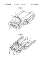
- FIG. 7 is a perspective view showing the external configuration of an exemplary embodiment of the invention.
- FIG. 8 is an exploded perspective view of a further embodiment of the invention having separate displaceable members in the sealant chamber.
- FIG. 9 is a cutaway perspective view of the embodiment of FIG. 8 in the assembled condition.
- a closure casing for housing splices between two cables only one of which is schematically represented at 12 .
- the cables may be conductors or optical fibres. It will be appreciated that only one half of the casing 11 is illustrated, the other half being a mirror image of substantially identical components at the opposite end and have been omitted for clarity.
- the closure casing 11 comprises a first or tray part 13 and a second or cover part 14 which meet along a longitudinal separation line generally indicated 15 in correspondence with which there is formed a longitudinal seal which may be of conventional form and which, therefore, will not be described in detail herein.
- the two parts 13 , 14 of the closure casing 11 define a main chamber 16 within which splices between the elongate cables 12 may be housed. Appropriate cables organisers, splice connectors and the equipment may be housed in the chamber 16 but are not illustrated here for clarity.
- the tray member 13 and cover member 14 have corresponding transverse partition walls 17 , 18 having respective grooves or channels (only one of which, channel 19 , is visible in FIG.
- Each crown flange 20 is formed as a semi-conical element with a plurality of flexible fingers extending axially from a radial flange 21 .
- Such elements are known and described, for example, in our earlier International Patent Application PCT/GB95/00469 published under International Publication No. WO 95/24756.
- the radial flange part 21 of a crown flange is received in the groove 19 to locate it in position, and the difference in diameter between the larger diameter end at the flange 21 and the smaller diameter end at the free end of the flexible fingers, defines the range of diameters of cable 12 which can be accommodated.
- the end portion of the lower tray part 13 , between the partition wall 17 and an end wall 22 thereof defines a sealing chamber 23 which is filled with a gel material 24 in use of the closure casing.
- a bottom wall of the sealing chamber 23 comprises a central, slightly domed, substantially rigid “piston” part 25 having a central boss 26 .
- the piston part 25 is circular in plan form, as can be seen in FIG. 2, and joined to the remainder of the bottom wall 27 of the sealing chamber 23 by a generally U-section roll seal 28 comprising a thin, integrally formed membrane joining the outer periphery of the piston member 25 with the circular inner perimeter a rigid part of the bottom wall 27 of the sealing chamber 23 .
- the thickness of the roll seal membrane 28 is considerably less than that of the bottom wall 27 or the piston part 25 although they are integrally formed of the same material. Due to the reduced dimensions of the wall thickness the roll seal part 28 is substantially flexible whilst the bottom wall 27 and the piston part 25 are substantially rigid.
- a shaft 29 having a threaded end portion and an enlarged head 30 received in a cavity in a central boss 31 of a circular reinforcing disc 32 which has a slightly larger diameter than that of the piston part 25 but slightly less than the inner perimeter of the bottom wall 27 .
- the cover part 14 of the casing has a corresponding configuration the components of which are identified with the same reference numerals as those used for the lower tray part, but distinguished with a ′.
- the cover part 14 differs from the tray part 13 only in the configuration of the end wall 22 ′ which in the cover part 14 has a tab 33 for engagement in a correspondingly shaped channel 34 .
- the shaft 29 passes through the apertured boss 26 ′ of the “piston” portion 25 ′ of an upper wall 27 ′ of the end part of the upper cover 14 and is engaged by a nut 35 which is captive in a cavity 36 of a control knob 37 . Between the nut 35 and the “piston” 25 ′ is a compression coil spring 38 .
- the gel filling 24 ( 24 ′ in the upper part) is preferably injection moulded into each half of the closure casing during manufacture.
- elongate cables 12 are laid into the seatings provided by the crown flanges 20 engaged in the grooves 19 of the partition wall 17 and a corresponding groove in the end wall 22 .
- Appropriate splicing operations are performed on the end of the cable 12 projecting into the main chamber 16 to join it, for example, to corresponding end portions of an aligned cable projecting into the chamber 16 from the opposite end (not shown) of the casing 11 .
- the cover 14 is then placed over the tray part 13 with suitable longitudinal seals made along the edges joining at the longitudinal junction line 15 . Such seals are known and will not be described herein.
- the gel fillings 24 , 24 ′ which have been introduced into the chamber 23 preferably by injection moulding (although pre-shaped blocks may alternatively although non-preferably be used) meet to form a complete filling for the interior of the chamber 23 and the threaded shaft 29 is then introduced through the aligned openings in the bosses 26 , 26 ′, the spring 38 is fitted over the end and the control knob 37 fitted by screwing the nut 35 on to the threaded end of the shaft 29 .
- the gel material 24 can be placed under a suitable compressive load by turning the knob 37 to compress the spring 38 by an appropriate extent. It is desirable that the spring 38 should not be fully compressed such that the adjacent turns thereof come into contact with one another since this would not allow relative separation of the movable wall parts (the “pistons” 25 , 25 ′) and to prevent this from happening, whilst nevertheless ensuring that the gel 24 is placed under a suitable compressive load, an indicator device acting to give the operator feedback as to the degree of compression of the spring 38 may be provided. Such device may, for example, be in the form of two interfering projections on corresponding relatively movable components, such as that described in International Patent Application published under Publication No. WO 92/22114 the disclosure of which is incorporated herein by reference.
- a suitable configuration of components is described hereinbelow with reference to FIG. 6 .
- This comprises oppositely directed projections 50 , 51 on the control knob 37 and the piston 25 ′ which interfere with one another to prevent further rotation of the knob 37 when this and the piston reach a predetermined separation which corresponds to a predetermined compression of the spring 38 less than full compression.
- Alternative arrangements may be made to indicate to the user that a suitable mid-range compression has been achieved, for example by providing a second spring which comes into play part way through the compression of the main spring 38 , or by a change in the shape of the screw thread or provision of, for example, a fibre washer all of which serve to provide an indication to the user by increasing the force which must be applied to the control knob 37 .
- FIG. 5 there is shown a schematic illustration of a part of the U-shape section of the roll seal 28 ′ of the cover part 14 .
- the roll seal 28 ′ effectively comprises three parts namely a radially inner limb 40 , a radially outer limb 41 and a bight portion 42 .
- the radially inner limb 40 In its relaxed state, as formed, the radially inner limb 40 has its maximum length whilst the radially outer limb 41 has its minimum length.
- the bight portion 42 obviously joins these two limbs and is formed from them as the roll seal moves upon displacement of the piston portion 25 ′ from the position shown in solid outline in FIG. 5 to the position shown in broken outline, in which position the radially inner and outer limbs 40 , 41 are of equal length.
- the circumference of the radially outer limb portion 41 is greater than that of the radially inner limb portion 40 so that the material of the roll seal is placed under tension by this movement, which is a stress the material is better capable of withstanding than compressive stress which would be the case if the displacement of the piston 25 ′ to move from its starting position to its working position resulted in transfer of material from the radially outer limb 41 towards the radially inner limb 40 .
- the described configuration is preferred, it is by no means impossible that an outwardly convex roll seal could be used.
- a single U-shape roll seal has been described, it would be possible for this to be a corrugated or bellows-configuration seal with more than one corrugation.
- FIG. 7 shows one proposed configuration for a closure casing of the invention.
- the upper and lower halves of the casing are held together by toggle clips 60 .
- This has the advantage of allowing the closure to be re-enterable to effect changes in the splice configuration or repairs as necessary.
- FIGS. 8 to 10 there is shown a closure casing, generally indicated 61 comprising two cooperating casing parts 62 , 63 in the form of half-shells which can be held together in juxtaposed relationship by a set of spring clips 64 each comprising a closed loop 65 of spring wire and a toggle lever 66 having pivot pins 66 A which engage in cooperating recesses 68 of the upper (as viewed in the drawings) casing half 62 whereby to clamp the two casing halves together.
- a closure casing generally indicated 61 comprising two cooperating casing parts 62 , 63 in the form of half-shells which can be held together in juxtaposed relationship by a set of spring clips 64 each comprising a closed loop 65 of spring wire and a toggle lever 66 having pivot pins 66 A which engage in cooperating recesses 68 of the upper (as viewed in the drawings) casing half 62 whereby to clamp the two casing halves together.
- FIG. 8 The lower (as viewed in the drawings) casing half 63 is shown in FIG. 8 with a portion adjacent its end cut away to illustrate the internal configuration of the sealing means at the end.
- a transverse end wall 67 has two arcuate, semi-circular notches 68 , 69 which, together with corresponding notches 70 , 71 in an end wall 72 of the “upper” casing half 62 form circular openings (only one of which, identified 73 , is visible in FIG. 9) through which passes an elongate article 74 , in this example a bundle of optical fibres or cables intended to be spliced or joined within the casing 61 .
- a second transverse wall 75 parallel to the transverse end wall 67 defines, with this latter, a chamber 77 for receiving a clamp member 78 loosely fitted within the chamber 77 and to be described in more detail below.
- a second transverse wall 76 closely adjacent the wall 75 defines a narrow slot 79 for receiving a lip 80 of a crown flange 81 , whereby to locate the crown flange in position over a lower plunger 82 having two shaped channels 83 , 84 for receiving respective parts of the crown flange 81 .
- the plunger 82 is located between the transverse wall 76 and a further wall (not visible in the drawings) which between them define a sealant chamber 85 which will be described in more detail below.
- a cylindrical sleeve 86 Projecting upwardly from a central portion of the plunger 82 is a cylindrical sleeve 86 which, as can be seen in FIG. 9, carries a helical internal rib forming a thread 87 for cooperation with a threaded part 88 of a stem 89 at the upper end of which is located an operating knob 90 .
- the rod 89 is located within a sleeve 91 of an upper plunger 92 a skirt portion of which engages over the cylindrical sleeve 86 when the casing 61 is assembled.
- the lower plunger 82 and upper plunger 92 define opposite facing walls of the sealant chamber 85 and can be caused to approach or separate from one another by manipulation of the knob 90 causing the shaft 89 to rotate thereby screwing the threaded portion 88 into or out from engagement with the thread 87 in the lower plunger 82 .
- the upper plunger 92 has shaped channels 93 for receiving cooperating crown flanges 94 .
- a smaller-diameter elongate article 95 is shown engaged between the crown flanges 81 , 94 at the relatively narrow tapered end which engages over the article 95 .
- Gel sealant of a type described hereinbefore may be introduced into the sealant chamber 85 , either by injection moulding as described above, or by the introduction of separate gel elements.
- a secure seal against the ingress of environmental contaminants into the interior of the casing can be achieved by turning the knob 90 to cause the plungers 82 and 92 to approach one another, maintaining a symmetrical configuration within the chamber 85 , and applying a compressive force to the gel.
- a coil spring 96 is engaged over the threaded shaft 88 between the knob 90 and the upper face of the plunger 92 , with a bearing plate 97 interposed between them, such that the force between the shaft 89 and the plunger 92 is transmitted via the spring 96 which is compressed as the shaft 89 is screwed into the plunger 82 thereby creating a residual energy store which maintains the compression on the gel in the manner described hereinabove in relationship to the embodiment of FIGS. 1 to 8 .
- a suitable arrangement for determining when an appropriate degree of compression of the spring 96 has been achieved may also be provided as described hereinbefore, although such arrangement is not illustrated in FIGS. 9 to 10 .
Landscapes
- Physics & Mathematics (AREA)
- General Physics & Mathematics (AREA)
- Optics & Photonics (AREA)
- Cable Accessories (AREA)
- Installation Of Indoor Wiring (AREA)
- Pressure Vessels And Lids Thereof (AREA)
- Package Closures (AREA)
- Auxiliary Devices For And Details Of Packaging Control (AREA)
- Light Guides In General And Applications Therefor (AREA)
- Insulating Bodies (AREA)
Applications Claiming Priority (5)
| Application Number | Priority Date | Filing Date | Title |
|---|---|---|---|
| GBGB9808963.4A GB9808963D0 (en) | 1998-04-28 | 1998-04-28 | A closure |
| GB9808963 | 1998-04-28 | ||
| GB9906210 | 1999-03-18 | ||
| GBGB9906210.1A GB9906210D0 (en) | 1999-03-18 | 1999-03-18 | A closure |
| PCT/GB1999/000993 WO1999056370A1 (fr) | 1998-04-28 | 1999-03-30 | Boitier |
Publications (1)
| Publication Number | Publication Date |
|---|---|
| US6344615B1 true US6344615B1 (en) | 2002-02-05 |
Family
ID=26313543
Family Applications (1)
| Application Number | Title | Priority Date | Filing Date |
|---|---|---|---|
| US09/673,756 Expired - Fee Related US6344615B1 (en) | 1998-04-28 | 1999-03-30 | Closure having an adjustable volume sealant chamber |
Country Status (11)
| Country | Link |
|---|---|
| US (1) | US6344615B1 (fr) |
| EP (1) | EP1074078A1 (fr) |
| JP (1) | JP2002513267A (fr) |
| CN (1) | CN1298565A (fr) |
| AR (1) | AR019098A1 (fr) |
| BR (1) | BR9910571A (fr) |
| CA (1) | CA2327704A1 (fr) |
| PE (1) | PE20000735A1 (fr) |
| PL (1) | PL343624A1 (fr) |
| TR (1) | TR200003133T2 (fr) |
| WO (1) | WO1999056370A1 (fr) |
Cited By (35)
| Publication number | Priority date | Publication date | Assignee | Title |
|---|---|---|---|---|
| US20020180163A1 (en) * | 1999-12-02 | 2002-12-05 | Thorsten Muller | Sealing body for longitudinally split cable fittings |
| US20050279692A1 (en) * | 2004-06-22 | 2005-12-22 | Luca Caleffi | Transducer-protector device for medical apparatus |
| US20060011372A1 (en) * | 2004-07-13 | 2006-01-19 | Thomas & Betts International, Inc. | Insulating cover for electrical connectors |
| US20060277858A1 (en) * | 2005-06-13 | 2006-12-14 | Inventec Corporation | Installing structure for modularized electronic device |
| US20090103876A1 (en) * | 2006-05-30 | 2009-04-23 | Wolf Kluwe | Cable Sleeve for the Structured Storage and Handling of Optical Waveguides Guided in Optical Waveguide Cables |
| US20090103877A1 (en) * | 2006-05-30 | 2009-04-23 | Wolf Kluwe | Cable Sleeve for the Structured Storage and Handling of Optical Waveguides Guided in Optical Waveguide Cables |
| WO2010092009A1 (fr) * | 2009-02-10 | 2010-08-19 | Tyco Electronics Raychem Bvba | Logement pour un ensemble de câbles de fibres optiques |
| US20130072053A1 (en) * | 2010-04-16 | 2013-03-21 | Grzegorz Fabrykowski | Sealing and strain relief device for data cables |
| US8879881B2 (en) | 2010-04-30 | 2014-11-04 | Corning Cable Systems Llc | Rotatable routing guide and assembly |
| US8913866B2 (en) | 2010-03-26 | 2014-12-16 | Corning Cable Systems Llc | Movable adapter panel |
| US8953924B2 (en) | 2011-09-02 | 2015-02-10 | Corning Cable Systems Llc | Removable strain relief brackets for securing fiber optic cables and/or optical fibers to fiber optic equipment, and related assemblies and methods |
| US8965168B2 (en) | 2010-04-30 | 2015-02-24 | Corning Cable Systems Llc | Fiber management devices for fiber optic housings, and related components and methods |
| US8985862B2 (en) | 2013-02-28 | 2015-03-24 | Corning Cable Systems Llc | High-density multi-fiber adapter housings |
| US8989547B2 (en) | 2011-06-30 | 2015-03-24 | Corning Cable Systems Llc | Fiber optic equipment assemblies employing non-U-width-sized housings and related methods |
| US8992099B2 (en) | 2010-02-04 | 2015-03-31 | Corning Cable Systems Llc | Optical interface cards, assemblies, and related methods, suited for installation and use in antenna system equipment |
| US8995812B2 (en) | 2012-10-26 | 2015-03-31 | Ccs Technology, Inc. | Fiber optic management unit and fiber optic distribution device |
| US9008485B2 (en) | 2011-05-09 | 2015-04-14 | Corning Cable Systems Llc | Attachment mechanisms employed to attach a rear housing section to a fiber optic housing, and related assemblies and methods |
| US9020320B2 (en) | 2008-08-29 | 2015-04-28 | Corning Cable Systems Llc | High density and bandwidth fiber optic apparatuses and related equipment and methods |
| US9038832B2 (en) | 2011-11-30 | 2015-05-26 | Corning Cable Systems Llc | Adapter panel support assembly |
| US9042702B2 (en) | 2012-09-18 | 2015-05-26 | Corning Cable Systems Llc | Platforms and systems for fiber optic cable attachment |
| US9059578B2 (en) | 2009-02-24 | 2015-06-16 | Ccs Technology, Inc. | Holding device for a cable or an assembly for use with a cable |
| US9075217B2 (en) | 2010-04-30 | 2015-07-07 | Corning Cable Systems Llc | Apparatuses and related components and methods for expanding capacity of fiber optic housings |
| US9116324B2 (en) | 2010-10-29 | 2015-08-25 | Corning Cable Systems Llc | Stacked fiber optic modules and fiber optic equipment configured to support stacked fiber optic modules |
| US9213161B2 (en) | 2010-11-05 | 2015-12-15 | Corning Cable Systems Llc | Fiber body holder and strain relief device |
| US9250409B2 (en) | 2012-07-02 | 2016-02-02 | Corning Cable Systems Llc | Fiber-optic-module trays and drawers for fiber-optic equipment |
| US9279951B2 (en) | 2010-10-27 | 2016-03-08 | Corning Cable Systems Llc | Fiber optic module for limited space applications having a partially sealed module sub-assembly |
| US9316804B2 (en) | 2012-05-18 | 2016-04-19 | Ccs Technology, Inc. | Cable closure |
| CN105745803A (zh) * | 2013-11-18 | 2016-07-06 | 睿迈有限公司 | 线缆紧固装置 |
| US20160268723A1 (en) * | 2013-10-21 | 2016-09-15 | Ampfibian Holdings Pty Ltd | Closure seal for electrical adaptor |
| US9519118B2 (en) | 2010-04-30 | 2016-12-13 | Corning Optical Communications LLC | Removable fiber management sections for fiber optic housings, and related components and methods |
| US9645317B2 (en) | 2011-02-02 | 2017-05-09 | Corning Optical Communications LLC | Optical backplane extension modules, and related assemblies suitable for establishing optical connections to information processing modules disposed in equipment racks |
| US10094996B2 (en) | 2008-08-29 | 2018-10-09 | Corning Optical Communications, Llc | Independently translatable modules and fiber optic equipment trays in fiber optic equipment |
| US10996414B1 (en) | 2020-03-23 | 2021-05-04 | Afl Telecommunications Llc | Butt closures and bases therefor |
| US11294135B2 (en) | 2008-08-29 | 2022-04-05 | Corning Optical Communications LLC | High density and bandwidth fiber optic apparatuses and related equipment and methods |
| US11561354B2 (en) | 2018-05-09 | 2023-01-24 | Afl Telecommunications Llc | Butt closures and bases therefor |
Families Citing this family (19)
| Publication number | Priority date | Publication date | Assignee | Title |
|---|---|---|---|---|
| US7214735B2 (en) * | 2004-02-02 | 2007-05-08 | 3M Innovative Properties Company | Microsphere-filled sealant materials |
| DE202007003989U1 (de) * | 2007-03-14 | 2007-07-05 | Ccs Technology Inc., Wilmington | Dichtungskörper einer Kabelmuffe |
| BE1017965A3 (fr) * | 2008-01-22 | 2010-02-02 | Sadinter Sogecomex | Boite et procede de jonction. |
| CN101662097B (zh) * | 2008-08-26 | 2011-10-12 | 泰科电子(上海)有限公司 | 线缆锁紧装置和具有该线缆锁紧装置的线缆连接器 |
| US8227696B2 (en) * | 2008-11-18 | 2012-07-24 | Tyco Electronics Corporation | Sealant-filled enclosures and methods for environmentally protecting a connection |
| JP5187527B2 (ja) * | 2009-02-25 | 2013-04-24 | 中国電力株式会社 | クロージャ |
| WO2010127376A2 (fr) * | 2009-05-06 | 2010-11-11 | Feller Gmbh | Dispositif pourvu d'une enveloppe en matière isolante |
| EP2330706B1 (fr) | 2009-12-03 | 2017-04-19 | CommScope Connectivity Belgium BVBA | Dispositif d'étanchéité à gel |
| CN102221735B (zh) * | 2010-04-16 | 2013-07-17 | 泰科电子(上海)有限公司 | 光缆接头盒 |
| EP2523287A1 (fr) * | 2011-05-10 | 2012-11-14 | Tyco Electronics Raychem BVBA | Dispositif d'étanchéité de câble doté d'un mur de confinement étanche doté de portions mobiles permettant d'accommoder les câbles de différentes tailles |
| EP2557442B1 (fr) * | 2011-08-12 | 2014-10-08 | CCS Technology, Inc. | Fermeture de câble |
| EP2557443B1 (fr) * | 2011-08-12 | 2014-03-05 | CCS Technology, Inc. | Fermeture de câble |
| EP2597744B1 (fr) * | 2011-11-24 | 2015-01-07 | CCS Technology, Inc. | Fermeture de câble |
| CN104641525B (zh) | 2012-07-02 | 2018-07-13 | 泰科电子瑞侃有限公司 | 可再进入的封壳 |
| DK3176890T3 (da) | 2012-07-02 | 2020-05-18 | CommScope Connectivity Belgium BVBA | Kabeltætningsenhed med flere tætningsmoduler |
| US9400363B2 (en) | 2012-07-02 | 2016-07-26 | CommScope Connectivity Belgium BVBA | Pressure actuated sealant assembly |
| ES2761909T3 (es) | 2012-07-02 | 2020-05-21 | CommScope Connectivity Belgium BVBA | Dispositivo de accionamiento de estanqueidad con indicador del nivel de accionamiento |
| US10840615B2 (en) | 2018-06-28 | 2020-11-17 | Te Connectivity Corporation | Connection enclosure assemblies, connector systems and methods for forming an enclosed connection between conductors |
| CN110501793B (zh) * | 2019-07-01 | 2020-07-17 | 国网浙江省电力有限公司衢州供电公司 | 密封效果好的光缆接头盒 |
Citations (13)
| Publication number | Priority date | Publication date | Assignee | Title |
|---|---|---|---|---|
| US4600261A (en) | 1982-10-12 | 1986-07-15 | Raychem Corporation | Apparatus and method for protection of electrical contacts |
| US4634207A (en) | 1982-10-12 | 1987-01-06 | Raychem Corporation | Apparatus and method for protection of a substrate |
| US4716183A (en) | 1985-11-22 | 1987-12-29 | Raychem Corp. | Styrene-diene block copolymer compositions |
| US4859809A (en) | 1988-04-27 | 1989-08-22 | Raychem Corporation | Splice case |
| WO1990005401A1 (fr) | 1988-11-09 | 1990-05-17 | N.V. Raychem S.A. | Ensemble de boitier |
| WO1992022114A1 (fr) | 1991-06-06 | 1992-12-10 | N.V. Raychem S.A. | Dispositif d'etancheite pour cables |
| WO1995015600A1 (fr) | 1993-12-01 | 1995-06-08 | Nv Raychem S.A. | Dispositif d'etancheite |
| WO1995024756A1 (fr) | 1994-03-07 | 1995-09-14 | N.V. Raychem S.A. | Agencement d'etancheite |
| WO1996002080A1 (fr) | 1994-07-11 | 1996-01-25 | Raychem Limited | Interconnexions electriques |
| WO1996019024A1 (fr) | 1994-12-12 | 1996-06-20 | N.V. Raychem S.A. | Dispositif d'etancheite |
| WO1997027655A1 (fr) | 1996-01-24 | 1997-07-31 | N.V. Raychem S.A. | Fermeture a boitier pour cable |
| WO1997045904A1 (fr) | 1996-05-31 | 1997-12-04 | N.V. Raychem S.A. | Article etanche |
| US6218620B1 (en) * | 1999-05-19 | 2001-04-17 | John M. Michel | Housing for telephone splices and the like and method |
-
1999
- 1999-03-30 CA CA002327704A patent/CA2327704A1/fr not_active Abandoned
- 1999-03-30 US US09/673,756 patent/US6344615B1/en not_active Expired - Fee Related
- 1999-03-30 EP EP99913493A patent/EP1074078A1/fr not_active Withdrawn
- 1999-03-30 PL PL99343624A patent/PL343624A1/xx unknown
- 1999-03-30 CN CN99805620A patent/CN1298565A/zh active Pending
- 1999-03-30 BR BR9910571-3A patent/BR9910571A/pt not_active Application Discontinuation
- 1999-03-30 WO PCT/GB1999/000993 patent/WO1999056370A1/fr not_active Application Discontinuation
- 1999-03-30 JP JP2000546437A patent/JP2002513267A/ja active Pending
- 1999-03-30 TR TR2000/03133T patent/TR200003133T2/xx unknown
- 1999-04-22 AR ARP990101875A patent/AR019098A1/es unknown
- 1999-04-27 PE PE1999000345A patent/PE20000735A1/es not_active Application Discontinuation
Patent Citations (13)
| Publication number | Priority date | Publication date | Assignee | Title |
|---|---|---|---|---|
| US4600261A (en) | 1982-10-12 | 1986-07-15 | Raychem Corporation | Apparatus and method for protection of electrical contacts |
| US4634207A (en) | 1982-10-12 | 1987-01-06 | Raychem Corporation | Apparatus and method for protection of a substrate |
| US4716183A (en) | 1985-11-22 | 1987-12-29 | Raychem Corp. | Styrene-diene block copolymer compositions |
| US4859809A (en) | 1988-04-27 | 1989-08-22 | Raychem Corporation | Splice case |
| WO1990005401A1 (fr) | 1988-11-09 | 1990-05-17 | N.V. Raychem S.A. | Ensemble de boitier |
| WO1992022114A1 (fr) | 1991-06-06 | 1992-12-10 | N.V. Raychem S.A. | Dispositif d'etancheite pour cables |
| WO1995015600A1 (fr) | 1993-12-01 | 1995-06-08 | Nv Raychem S.A. | Dispositif d'etancheite |
| WO1995024756A1 (fr) | 1994-03-07 | 1995-09-14 | N.V. Raychem S.A. | Agencement d'etancheite |
| WO1996002080A1 (fr) | 1994-07-11 | 1996-01-25 | Raychem Limited | Interconnexions electriques |
| WO1996019024A1 (fr) | 1994-12-12 | 1996-06-20 | N.V. Raychem S.A. | Dispositif d'etancheite |
| WO1997027655A1 (fr) | 1996-01-24 | 1997-07-31 | N.V. Raychem S.A. | Fermeture a boitier pour cable |
| WO1997045904A1 (fr) | 1996-05-31 | 1997-12-04 | N.V. Raychem S.A. | Article etanche |
| US6218620B1 (en) * | 1999-05-19 | 2001-04-17 | John M. Michel | Housing for telephone splices and the like and method |
Non-Patent Citations (2)
| Title |
|---|
| Copy of International Preliminary Examination Report, No date. |
| Copy of International Search Report, No date. |
Cited By (67)
| Publication number | Priority date | Publication date | Assignee | Title |
|---|---|---|---|---|
| US6802512B2 (en) * | 1999-12-02 | 2004-10-12 | Ccs Technology, Inc. | Sealing body for longitudinally split cable fittings |
| US20020180163A1 (en) * | 1999-12-02 | 2002-12-05 | Thorsten Muller | Sealing body for longitudinally split cable fittings |
| US20050279692A1 (en) * | 2004-06-22 | 2005-12-22 | Luca Caleffi | Transducer-protector device for medical apparatus |
| US7520919B2 (en) | 2004-06-22 | 2009-04-21 | Gambro Lundia Ab | Transducer-protector device for medical apparatus |
| US20060011372A1 (en) * | 2004-07-13 | 2006-01-19 | Thomas & Betts International, Inc. | Insulating cover for electrical connectors |
| US20060180333A1 (en) * | 2004-07-13 | 2006-08-17 | Thomas & Betts International, Inc. | Insulating cover for electrical connectors |
| US7094972B2 (en) | 2004-07-13 | 2006-08-22 | Thomas & Betts International, Inc. | Insulating cover for electrical connectors |
| US20060277858A1 (en) * | 2005-06-13 | 2006-12-14 | Inventec Corporation | Installing structure for modularized electronic device |
| US8055114B2 (en) | 2006-05-30 | 2011-11-08 | Ccs Technology, Inc. | Cable sleeve for the structured storage and handling of optical waveguides guided in optical waveguide cables |
| US20090103876A1 (en) * | 2006-05-30 | 2009-04-23 | Wolf Kluwe | Cable Sleeve for the Structured Storage and Handling of Optical Waveguides Guided in Optical Waveguide Cables |
| US20090103877A1 (en) * | 2006-05-30 | 2009-04-23 | Wolf Kluwe | Cable Sleeve for the Structured Storage and Handling of Optical Waveguides Guided in Optical Waveguide Cables |
| US7689090B2 (en) * | 2006-05-30 | 2010-03-30 | Ccs Technology, Inc. | Cable sleeve for the structured storage and handling of optical waveguides guided in optical waveguide cables |
| US9020320B2 (en) | 2008-08-29 | 2015-04-28 | Corning Cable Systems Llc | High density and bandwidth fiber optic apparatuses and related equipment and methods |
| US10564378B2 (en) | 2008-08-29 | 2020-02-18 | Corning Optical Communications LLC | High density and bandwidth fiber optic apparatuses and related equipment and methods |
| US10094996B2 (en) | 2008-08-29 | 2018-10-09 | Corning Optical Communications, Llc | Independently translatable modules and fiber optic equipment trays in fiber optic equipment |
| US11754796B2 (en) | 2008-08-29 | 2023-09-12 | Corning Optical Communications LLC | Independently translatable modules and fiber optic equipment trays in fiber optic equipment |
| US10120153B2 (en) | 2008-08-29 | 2018-11-06 | Corning Optical Communications, Llc | Independently translatable modules and fiber optic equipment trays in fiber optic equipment |
| US11609396B2 (en) | 2008-08-29 | 2023-03-21 | Corning Optical Communications LLC | High density and bandwidth fiber optic apparatuses and related equipment and methods |
| US10126514B2 (en) | 2008-08-29 | 2018-11-13 | Corning Optical Communications, Llc | Independently translatable modules and fiber optic equipment trays in fiber optic equipment |
| US11294136B2 (en) | 2008-08-29 | 2022-04-05 | Corning Optical Communications LLC | High density and bandwidth fiber optic apparatuses and related equipment and methods |
| US11294135B2 (en) | 2008-08-29 | 2022-04-05 | Corning Optical Communications LLC | High density and bandwidth fiber optic apparatuses and related equipment and methods |
| US11092767B2 (en) | 2008-08-29 | 2021-08-17 | Corning Optical Communications LLC | High density and bandwidth fiber optic apparatuses and related equipment and methods |
| US11086089B2 (en) | 2008-08-29 | 2021-08-10 | Corning Optical Communications LLC | High density and bandwidth fiber optic apparatuses and related equipment and methods |
| US10852499B2 (en) | 2008-08-29 | 2020-12-01 | Corning Optical Communications LLC | High density and bandwidth fiber optic apparatuses and related equipment and methods |
| US10606014B2 (en) | 2008-08-29 | 2020-03-31 | Corning Optical Communications LLC | Independently translatable modules and fiber optic equipment trays in fiber optic equipment |
| US10222570B2 (en) | 2008-08-29 | 2019-03-05 | Corning Optical Communications LLC | Independently translatable modules and fiber optic equipment trays in fiber optic equipment |
| US10459184B2 (en) | 2008-08-29 | 2019-10-29 | Corning Optical Communications LLC | High density and bandwidth fiber optic apparatuses and related equipment and methods |
| US9910236B2 (en) | 2008-08-29 | 2018-03-06 | Corning Optical Communications LLC | High density and bandwidth fiber optic apparatuses and related equipment and methods |
| US10444456B2 (en) | 2008-08-29 | 2019-10-15 | Corning Optical Communications LLC | High density and bandwidth fiber optic apparatuses and related equipment and methods |
| US10422971B2 (en) | 2008-08-29 | 2019-09-24 | Corning Optical Communicatinos LLC | High density and bandwidth fiber optic apparatuses and related equipment and methods |
| US10416405B2 (en) | 2008-08-29 | 2019-09-17 | Corning Optical Communications LLC | Independently translatable modules and fiber optic equipment trays in fiber optic equipment |
| EP2239609A1 (fr) * | 2009-02-10 | 2010-10-13 | Tyco Electronics Raychem BVBA | Boîtier pour assemblage de câbles à fibres optiques |
| WO2010092009A1 (fr) * | 2009-02-10 | 2010-08-19 | Tyco Electronics Raychem Bvba | Logement pour un ensemble de câbles de fibres optiques |
| CN102334056B (zh) * | 2009-02-10 | 2014-11-19 | 泰科电子瑞侃有限公司 | 用于光学纤维线缆组件的壳体 |
| US8634688B2 (en) | 2009-02-10 | 2014-01-21 | Tyco Electronics Raychem Bvba | Housing for an optical fiber cable assembly |
| CN102334056A (zh) * | 2009-02-10 | 2012-01-25 | 泰科电子瑞侃有限公司 | 用于光学纤维线缆组件的壳体 |
| US9059578B2 (en) | 2009-02-24 | 2015-06-16 | Ccs Technology, Inc. | Holding device for a cable or an assembly for use with a cable |
| US9075216B2 (en) | 2009-05-21 | 2015-07-07 | Corning Cable Systems Llc | Fiber optic housings configured to accommodate fiber optic modules/cassettes and fiber optic panels, and related components and methods |
| US8992099B2 (en) | 2010-02-04 | 2015-03-31 | Corning Cable Systems Llc | Optical interface cards, assemblies, and related methods, suited for installation and use in antenna system equipment |
| US8913866B2 (en) | 2010-03-26 | 2014-12-16 | Corning Cable Systems Llc | Movable adapter panel |
| US20130072053A1 (en) * | 2010-04-16 | 2013-03-21 | Grzegorz Fabrykowski | Sealing and strain relief device for data cables |
| US9022814B2 (en) * | 2010-04-16 | 2015-05-05 | Ccs Technology, Inc. | Sealing and strain relief device for data cables |
| AU2011265751B2 (en) * | 2010-04-16 | 2015-09-10 | Corning Optical Communications LLC | Sealing and strain relief device for data cables |
| US9075217B2 (en) | 2010-04-30 | 2015-07-07 | Corning Cable Systems Llc | Apparatuses and related components and methods for expanding capacity of fiber optic housings |
| US8879881B2 (en) | 2010-04-30 | 2014-11-04 | Corning Cable Systems Llc | Rotatable routing guide and assembly |
| US9519118B2 (en) | 2010-04-30 | 2016-12-13 | Corning Optical Communications LLC | Removable fiber management sections for fiber optic housings, and related components and methods |
| US8965168B2 (en) | 2010-04-30 | 2015-02-24 | Corning Cable Systems Llc | Fiber management devices for fiber optic housings, and related components and methods |
| US9279951B2 (en) | 2010-10-27 | 2016-03-08 | Corning Cable Systems Llc | Fiber optic module for limited space applications having a partially sealed module sub-assembly |
| US9116324B2 (en) | 2010-10-29 | 2015-08-25 | Corning Cable Systems Llc | Stacked fiber optic modules and fiber optic equipment configured to support stacked fiber optic modules |
| US9213161B2 (en) | 2010-11-05 | 2015-12-15 | Corning Cable Systems Llc | Fiber body holder and strain relief device |
| US10481335B2 (en) | 2011-02-02 | 2019-11-19 | Corning Optical Communications, Llc | Dense shuttered fiber optic connectors and assemblies suitable for establishing optical connections for optical backplanes in equipment racks |
| US9645317B2 (en) | 2011-02-02 | 2017-05-09 | Corning Optical Communications LLC | Optical backplane extension modules, and related assemblies suitable for establishing optical connections to information processing modules disposed in equipment racks |
| US9008485B2 (en) | 2011-05-09 | 2015-04-14 | Corning Cable Systems Llc | Attachment mechanisms employed to attach a rear housing section to a fiber optic housing, and related assemblies and methods |
| US8989547B2 (en) | 2011-06-30 | 2015-03-24 | Corning Cable Systems Llc | Fiber optic equipment assemblies employing non-U-width-sized housings and related methods |
| US8953924B2 (en) | 2011-09-02 | 2015-02-10 | Corning Cable Systems Llc | Removable strain relief brackets for securing fiber optic cables and/or optical fibers to fiber optic equipment, and related assemblies and methods |
| US9038832B2 (en) | 2011-11-30 | 2015-05-26 | Corning Cable Systems Llc | Adapter panel support assembly |
| US9316804B2 (en) | 2012-05-18 | 2016-04-19 | Ccs Technology, Inc. | Cable closure |
| US9250409B2 (en) | 2012-07-02 | 2016-02-02 | Corning Cable Systems Llc | Fiber-optic-module trays and drawers for fiber-optic equipment |
| US9042702B2 (en) | 2012-09-18 | 2015-05-26 | Corning Cable Systems Llc | Platforms and systems for fiber optic cable attachment |
| US8995812B2 (en) | 2012-10-26 | 2015-03-31 | Ccs Technology, Inc. | Fiber optic management unit and fiber optic distribution device |
| US8985862B2 (en) | 2013-02-28 | 2015-03-24 | Corning Cable Systems Llc | High-density multi-fiber adapter housings |
| US9601865B2 (en) * | 2013-10-21 | 2017-03-21 | Ampfibian Holdings Pty. Ltd | Closure seal for electrical adaptor |
| US20160268723A1 (en) * | 2013-10-21 | 2016-09-15 | Ampfibian Holdings Pty Ltd | Closure seal for electrical adaptor |
| CN105745803A (zh) * | 2013-11-18 | 2016-07-06 | 睿迈有限公司 | 线缆紧固装置 |
| US11561354B2 (en) | 2018-05-09 | 2023-01-24 | Afl Telecommunications Llc | Butt closures and bases therefor |
| US10996414B1 (en) | 2020-03-23 | 2021-05-04 | Afl Telecommunications Llc | Butt closures and bases therefor |
| US11500170B2 (en) | 2020-03-23 | 2022-11-15 | Afl Telecommunications Llc | Butt closures and bases therefor |
Also Published As
| Publication number | Publication date |
|---|---|
| AR019098A1 (es) | 2001-12-26 |
| BR9910571A (pt) | 2001-01-16 |
| PE20000735A1 (es) | 2000-08-16 |
| CN1298565A (zh) | 2001-06-06 |
| CA2327704A1 (fr) | 1999-11-04 |
| PL343624A1 (en) | 2001-08-27 |
| JP2002513267A (ja) | 2002-05-08 |
| EP1074078A1 (fr) | 2001-02-07 |
| TR200003133T2 (tr) | 2001-03-21 |
| WO1999056370A1 (fr) | 1999-11-04 |
Similar Documents
| Publication | Publication Date | Title |
|---|---|---|
| US6344615B1 (en) | Closure having an adjustable volume sealant chamber | |
| CA1317650C (fr) | Manchon d'epissure | |
| US4405083A (en) | Moulding apparatus for encapsulating cable splices | |
| US4451696A (en) | Toolless splice sealant device | |
| US3992569A (en) | Protective cable enclosure, cable assembly including the same, and method of encapsulating a cable in a protective enclosure | |
| EP0749641B1 (fr) | Agencement d'etancheite | |
| AU721422B2 (en) | Cable closure | |
| US4039742A (en) | Waterproof cable splice enclosure kit | |
| EP0731998B1 (fr) | Plaque d'extrémité servant de joint d'étanchéité autour d'un objet allongé | |
| FI115346B (fi) | Kaapelinjatkosmuhvi | |
| US7062851B2 (en) | Through-fittings and below grade junction boxes equipped with same | |
| US4295005A (en) | Cable splice closure | |
| AU757414B2 (en) | Cable closure | |
| KR100337568B1 (ko) | 케이블밀봉장치 | |
| US2621228A (en) | Cable splicing sleeve with sealing chambers | |
| US5426715A (en) | Oval port seal and method used for an optical fiber cable closure | |
| WO2009082603A1 (fr) | Article rétractable à froid et procédé d'utilisation d'article rétractable à froid | |
| EP0770277B1 (fr) | Interconnexions electriques | |
| US3796823A (en) | Splice case with gas tight seal | |
| AU7502294A (en) | Sealing member | |
| RU2187184C2 (ru) | Изделие и герметизирующий элемент | |
| EP0812482A1 (fr) | Gaine d'epissure pour cables de telecommunication enterres | |
| NO148313B (no) | Ledningsgjennomfoering for elektriske ledninger. | |
| RU2136095C1 (ru) | Устройство для сращивания кабелей | |
| MXPA00010626A (en) | A closure |
Legal Events
| Date | Code | Title | Description |
|---|---|---|---|
| AS | Assignment |
Owner name: TYCO ELECTRONICS RAYCHEM N.V., BELGIUM Free format text: ASSIGNMENT OF ASSIGNORS INTEREST;ASSIGNORS:NOLF, JEAN-MARIE ETIENNE;LEGRAND, JOHAN;BUEKERS, VALERE;AND OTHERS;REEL/FRAME:011443/0179;SIGNING DATES FROM 19991005 TO 19991022 |
|
| REMI | Maintenance fee reminder mailed | ||
| LAPS | Lapse for failure to pay maintenance fees | ||
| STCH | Information on status: patent discontinuation |
Free format text: PATENT EXPIRED DUE TO NONPAYMENT OF MAINTENANCE FEES UNDER 37 CFR 1.362 |
|
| FP | Lapsed due to failure to pay maintenance fee |
Effective date: 20060205 |