US6308564B1 - Method and apparatus for determining the quantity and quality of a fluid - Google Patents
Method and apparatus for determining the quantity and quality of a fluid Download PDFInfo
- Publication number
- US6308564B1 US6308564B1 US09/154,561 US15456198A US6308564B1 US 6308564 B1 US6308564 B1 US 6308564B1 US 15456198 A US15456198 A US 15456198A US 6308564 B1 US6308564 B1 US 6308564B1
- Authority
- US
- United States
- Prior art keywords
- fluid
- resistance element
- quality
- temperature
- voltage
- Prior art date
- Legal status (The legal status is an assumption and is not a legal conclusion. Google has not performed a legal analysis and makes no representation as to the accuracy of the status listed.)
- Expired - Fee Related
Links
Images


Classifications
-
- G—PHYSICS
- G01—MEASURING; TESTING
- G01F—MEASURING VOLUME, VOLUME FLOW, MASS FLOW OR LIQUID LEVEL; METERING BY VOLUME
- G01F23/00—Indicating or measuring liquid level or level of fluent solid material, e.g. indicating in terms of volume or indicating by means of an alarm
- G01F23/22—Indicating or measuring liquid level or level of fluent solid material, e.g. indicating in terms of volume or indicating by means of an alarm by measuring physical variables, other than linear dimensions, pressure or weight, dependent on the level to be measured, e.g. by difference of heat transfer of steam or water
- G01F23/24—Indicating or measuring liquid level or level of fluent solid material, e.g. indicating in terms of volume or indicating by means of an alarm by measuring physical variables, other than linear dimensions, pressure or weight, dependent on the level to be measured, e.g. by difference of heat transfer of steam or water by measuring variations of resistance of resistors due to contact with conductor fluid
- G01F23/246—Indicating or measuring liquid level or level of fluent solid material, e.g. indicating in terms of volume or indicating by means of an alarm by measuring physical variables, other than linear dimensions, pressure or weight, dependent on the level to be measured, e.g. by difference of heat transfer of steam or water by measuring variations of resistance of resistors due to contact with conductor fluid thermal devices
- G01F23/247—Indicating or measuring liquid level or level of fluent solid material, e.g. indicating in terms of volume or indicating by means of an alarm by measuring physical variables, other than linear dimensions, pressure or weight, dependent on the level to be measured, e.g. by difference of heat transfer of steam or water by measuring variations of resistance of resistors due to contact with conductor fluid thermal devices for discrete levels
- G01F23/248—Constructional details; Mounting of probes
-
- G—PHYSICS
- G01—MEASURING; TESTING
- G01F—MEASURING VOLUME, VOLUME FLOW, MASS FLOW OR LIQUID LEVEL; METERING BY VOLUME
- G01F23/00—Indicating or measuring liquid level or level of fluent solid material, e.g. indicating in terms of volume or indicating by means of an alarm
- G01F23/22—Indicating or measuring liquid level or level of fluent solid material, e.g. indicating in terms of volume or indicating by means of an alarm by measuring physical variables, other than linear dimensions, pressure or weight, dependent on the level to be measured, e.g. by difference of heat transfer of steam or water
- G01F23/24—Indicating or measuring liquid level or level of fluent solid material, e.g. indicating in terms of volume or indicating by means of an alarm by measuring physical variables, other than linear dimensions, pressure or weight, dependent on the level to be measured, e.g. by difference of heat transfer of steam or water by measuring variations of resistance of resistors due to contact with conductor fluid
- G01F23/246—Indicating or measuring liquid level or level of fluent solid material, e.g. indicating in terms of volume or indicating by means of an alarm by measuring physical variables, other than linear dimensions, pressure or weight, dependent on the level to be measured, e.g. by difference of heat transfer of steam or water by measuring variations of resistance of resistors due to contact with conductor fluid thermal devices
- G01F23/247—Indicating or measuring liquid level or level of fluent solid material, e.g. indicating in terms of volume or indicating by means of an alarm by measuring physical variables, other than linear dimensions, pressure or weight, dependent on the level to be measured, e.g. by difference of heat transfer of steam or water by measuring variations of resistance of resistors due to contact with conductor fluid thermal devices for discrete levels
-
- G—PHYSICS
- G01—MEASURING; TESTING
- G01N—INVESTIGATING OR ANALYSING MATERIALS BY DETERMINING THEIR CHEMICAL OR PHYSICAL PROPERTIES
- G01N27/00—Investigating or analysing materials by the use of electric, electrochemical, or magnetic means
- G01N27/02—Investigating or analysing materials by the use of electric, electrochemical, or magnetic means by investigating impedance
- G01N27/04—Investigating or analysing materials by the use of electric, electrochemical, or magnetic means by investigating impedance by investigating resistance
- G01N27/14—Investigating or analysing materials by the use of electric, electrochemical, or magnetic means by investigating impedance by investigating resistance of an electrically-heated body in dependence upon change of temperature
- G01N27/18—Investigating or analysing materials by the use of electric, electrochemical, or magnetic means by investigating impedance by investigating resistance of an electrically-heated body in dependence upon change of temperature caused by changes in the thermal conductivity of a surrounding material to be tested
-
- G—PHYSICS
- G01—MEASURING; TESTING
- G01N—INVESTIGATING OR ANALYSING MATERIALS BY DETERMINING THEIR CHEMICAL OR PHYSICAL PROPERTIES
- G01N33/00—Investigating or analysing materials by specific methods not covered by groups G01N1/00 - G01N31/00
- G01N33/26—Oils; viscous liquids; paints; inks
- G01N33/28—Oils, i.e. hydrocarbon liquids
- G01N33/2888—Lubricating oil characteristics, e.g. deterioration
-
- G—PHYSICS
- G01—MEASURING; TESTING
- G01R—MEASURING ELECTRIC VARIABLES; MEASURING MAGNETIC VARIABLES
- G01R17/00—Measuring arrangements involving comparison with a reference value, e.g. bridge
- G01R17/02—Arrangements in which the value to be measured is automatically compared with a reference value
Definitions
- the invention relates to a method and an apparatus for determining and/or monitoring the quantity and quality of a fluid in which a lowering of the boiling temperature is symptomatic of a deterioration in quality. This is the case in particular with hygroscopic fluids, for example with glycol-based brake fluids or with engine oil.
- DE 41 13 443 C2 discloses an apparatus for detecting a liquid or gaseous medium, in particular a fluid filled to a certain level in a vessel, having at least one sensor unit which can be brought into contact with the medium.
- a heating element and a temperature sensor are used, the influencing of the temperature sensor by the heating element taking place in a way dependent on the presence or absence of fluid of the medium to be tested.
- the invention is based on the object of specifying a method and apparatus with which both the filling level or the quantity and the condition or quality of a fluid are automatically determined in a simple but reliable way.
- the method according to the invention has the advantage that the determination or measurement of the quantity and quality of the brake fluids in the system can be carried out at any time and by personnel who are not specially trained, without taking an inordinate amount of time.
- the method according to the invention is also suitable for monitoring other fluids, such as engine oil for example.
- a further advantageous design of the invention comprises determining the condition or quality of the fluid by raising the temperature of the temperature-dependent resistance element by applying to it a current of such an intensity that the boiling temperature of the fluid to be tested is not quite reached if it is of a given quality, by at the same time measuring the voltage across the temperature-dependent resistance element and by comparing this voltage characteristic with the voltage characteristics typical of different qualities.
- the temperature of a heating. resistance element is increased by applying to it a current of such an intensity that the boiling temperature of the fluid to be tested is not quite reached if it is of a given quality, by at the same time measuring the voltage across the temperature-dependent resistance element when it is supplied with current of low intensity and by comparing this voltage characteristic with the voltage characteristics typical of different qualities.
- the measured voltage value it has proven to be expedient here for the measured voltage value to be used for calculating the ambient temperature immediately after switching on the current and for the value obtained from this to be stored and taken into consideration when supplying current to the heating resistance element.
- the temperature of the fluid prefferably increased by applying current to the sensor containing a temperature-dependent resistance element, by at the same time determining the filling level by measuring the voltage across the temperature-dependent resistance element, by then using this voltage as a criterion for initiating the quality determination or not initiating it if the fluid level is low, by then, if proceeding with the determination of the quality of the fluid, applying to a heating resistance element contained in the sensor a current of such an intensity that the boiling temperature of the fluid to be tested is not quite reached if it is of a given quality, by at the same time measuring the voltage across the temperature-dependent resistance element supplied with current of low intensity and by finally comparing this voltage characteristic with the voltage characteristics typical of different qualities, an automatic signaling of the filling level and quality of the fluid taking place optically and/or acoustically.
- measurements need be performed only at relatively large time intervals, measurements while the motor vehicle is at a standstill being preferable.
- the determination of the filling level and/or the determination of the quality of the fluid take(s) place in the time between opening a motor vehicle and starting the engine of the motor vehicle.
- An apparatus for carrying out the method according to the invention comprises the sensor arranged in the fluid system being connected to a measuring instrument, which includes on the one hand a current source for supplying current to the sensor and on the other hand a voltmeter for determining the voltage at the sensor, and furthermore comprises the provision of a computer for controlling the measuring sequence and also an optical and/or acoustic display device.
- the senor comprises a temperature-dependent resistance element.
- the senor has in addition to the temperature-dependent resistance element a heating resistance element.
- the two resistance elements are arranged close to each other. It has proven to be expedient for the heating resistance element to be arranged underneath the temperature-dependent resistance element.
- the hydraulic fluid system is a braking system with a glycol-based brake fluid.
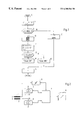
- FIG. 1 shows a flow diagram of the method according to the invention for determining the quantity and quality of a hydraulic fluid
- FIG. 2 shows a block diagram of the apparatus for carrying out the method according to the invention
- FIG. 3 shows one design of the sensor
- FIG. 4 shows various arrangements of the resistance elements in the fluid
- FIG. 5 shows a current/time diagram of the temperature-dependent resistance
- FIG. 6 shows a voltage/time diagram of the temperature-dependent resistance
- FIG. 7 shows a current/time diagram of the two resistance elements
- FIG. 8 shows a voltage/time diagram of the resistance element 1 with the voltage/time characteristic for a fluid of high quality and a fluid of lower quality.
- the flow chart represented in FIG. 1 for determining the quantity and quality of a fluid in a hydraulic system may, for example, be stored as a program in a microcomputer.
- the flow chart proceeds at B for the filling level measurement by applying a current I 1 during the time t to the temperature-dependent resistance of the sensor and, at the same time, measuring a voltage U across the temperature-dependent resistance.
- the message “filling level okay” takes place at the yes output and can be displayed optically and/or acoustically at D.
- the limit value NIVlimit specified in the block C of the flow diagram is in this case great enough that a quality measurement takes place only if the entire sensor is covered with fluid. If the difference ⁇ U between the voltage values U 0 and U 1 is below the limit value NIVlimit, there is emitted at the no output a signal to the effect that a quality measurement is not possible, since the filling level is below a certain level. At E, a corresponding optical and/or acoustic warning message is then emitted.
- the temperature-dependent resistance element is supplied with current I 1 and, on the other hand, the heating resistance element is supplied with current I 2 . At the same time the voltage U across the temperature-dependent resistance element 1 is measured.
- the measured voltage values are then compared with at least one limit value Quallimit, above which a “quality okay” message takes place at the yes output and can be optically and/or acoustically displayed at H. If the voltage characteristic of the measured voltage values lies below one or more limit values Quallimit, there is emitted at the no output of the block G a signal with the effect that an optical and/or acoustic message of the inadequate quality of the fluid is emitted at K.
- the boiling point in the new state is about 200° C., while water absorption may cause the boiling point to drop to 120° C. for example.
- a mandatory waiting time at L prevents the immediate restarting of the sequence at A before the fluid to be investigated has cooled down.
- FIG. 2 shows a block diagram with the temperature-dependent resistance element 1 and the heating resistance element 2 , which are connected to current sources 3 and 4 to be provided with current I 1 and I 2 .
- the voltage U present across the temperature-dependent resistance element 1 is determined at the same time.
- the sequence of this method is controlled by a microcomputer 7 , to the output of which there is also connected an optical-acoustic display device 8 .
- FIG. 3 shows a sensor in a perspective representation. This comprises two resistance elements 1 , 2 arranged in the immediate vicinity of each other in holding devices 11 , 12 , the temperature-dependent resistance element 1 expediently being arranged above the heating resistance element 2 .
- the temperature-dependent resistance element 1 For filling level or level measurement, only the temperature-dependent resistance element 1 is used; according to FIG. 4 a, this resistance element may also be arranged vertically with respect to the fluid level or, according to FIG. 4 b, it may be arranged parallel to the fluid level.
- This resistance element 1 is operated as a heater and resistor simultaneously. Since the dissipation of heat from the resistance element 1 takes place to different degrees inside and outside the fluid, a defined, constant heating current I 1 is set in such a way that the different heat dissipation behavior of the resistance element 1 is reflected in a clearly measurable way by a change in its resistance value.
- the second resistance element 2 is operated as a heating resistance element.
- the arrangement of the two resistance elements 1 , 2 is such that fluid heated or made to boil by the resistance element 2 influences the heat dissipation conditions at the resistance element 1 . From at least one voltage U measured across the resistance element 1 , a good/bad statement on the quality of the fluid can then be derived by comparison with known voltage values.
- the two parallel lying resistance elements 1 and 2 may likewise—as shown in FIGS. 4 c and 4 d —be arranged perpendicularly, at an angle or parallel to the fluid level, but must always be entirely covered by the fluid for this measurement. To maximize the influence of the heating resistance element 2 on the temperature-dependent resistance element 1 , placement of the resistance element 2 underneath the resistance element 1 is advisable.
- the temperature-dependent resistance element 1 dipping obliquely or vertically into the fluid is flowed through by a constant electric heating current I 1 during a time window t.
- This causes the element to heat up and, as it does so, to change its electrical resistance.
- the voltage across the resistance element 1 is measured constantly, or at least at the beginning and end of the current-applying phase according to FIG. 6 .
- the heat of the resistance element 1 is dissipated to a greater degree from its region dipping into the fluid than from its region located above the fluid. Consequently, different fluid levels are reflected by different dissipations of heat and accordingly by a different voltage U across the resistance element 1 .
- the fluid level can consequently be determined from at least two voltages U 0 and U 1 measured across the resistance element 1 .
- the heat dissipation behavior changes abruptly, according to whether the resistance element is within the fluid or outside it.
- Such an arrangement can establish, for example, the existence of a fluid at a specific filling height.
- the boiling temperature may be used as a measure of quality.
- the further resistance element 2 may then serve as a heating resistance element, which is flowed through by a constant electric current I 2 during a time window t, according to FIG. 7 .
- the current intensity is in this case chosen such that the boiling temperature of the fluid to be tested is not quite reached at the maximum quality or a given quality. If the quality of the fluid to be checked decreases due to water absorption, the heating resistance element 2 makes the fluid boil.
- the boiling of the fluid causes the resistance element 1 to then be surrounded by rising bubbles and vapor instead of by fluid.
- the resistance element 1 is flowed through constantly by a low current I 1 , which serves merely for allowing the voltage across the element 1 to be measured. Accordingly, the current intensity I 1 during the quality measurement is chosen such that no heating effect emanates from the resistance element 1 .
- the rise in voltage across the resistance element 1 is more pronounced in a brake fluid of higher quality (curve a) than in a brake fluid of lower quality (curve b). Furthermore, in a brake fluid of lower quality the further progression of the voltage characteristic is less steady and more volatile, since a vaporization takes place when the resistance element 2 is heated up, whereby small bubbles are constantly formed on it and released again. In this case, the coldness produced by the vaporization is to be regarded as temperature-lowering at resistance element 1 , accordingly as resistance-influencing.
- the good/bad evaluation can be realized particularly simply if the voltage level is measured at a number of characteristic points in time (c, d) and is compared with typical voltage values of a good or bad brake fluid.
Applications Claiming Priority (2)
| Application Number | Priority Date | Filing Date | Title |
|---|---|---|---|
| DE19741892A DE19741892C2 (de) | 1997-09-23 | 1997-09-23 | Verfahren und Vorrichtung zur Bestimmung der Quantität und Qualität einer Flüssigkeit |
| DE19741892 | 1997-09-23 |
Publications (1)
| Publication Number | Publication Date |
|---|---|
| US6308564B1 true US6308564B1 (en) | 2001-10-30 |
Family
ID=7843307
Family Applications (1)
| Application Number | Title | Priority Date | Filing Date |
|---|---|---|---|
| US09/154,561 Expired - Fee Related US6308564B1 (en) | 1997-09-23 | 1998-09-16 | Method and apparatus for determining the quantity and quality of a fluid |
Country Status (2)
| Country | Link |
|---|---|
| US (1) | US6308564B1 (de) |
| DE (1) | DE19741892C2 (de) |
Cited By (6)
| Publication number | Priority date | Publication date | Assignee | Title |
|---|---|---|---|---|
| US20040133337A1 (en) * | 2002-12-25 | 2004-07-08 | Fuji Jukogyo Kabushiki Kaisha | Fuel quantity display device |
| US20040190587A1 (en) * | 2002-11-27 | 2004-09-30 | Heinz Eisenschmid | Device and method for determining the boiling point of a liquid |
| US20050262938A1 (en) * | 2003-12-08 | 2005-12-01 | Carlson Gerard J | Methods and apparatus for media level measurement |
| EP1762847A3 (de) * | 2005-09-09 | 2010-06-02 | HONDA MOTOR CO., Ltd. | Ölwanne für Brennkraftmaschine |
| US10585057B2 (en) | 2014-12-16 | 2020-03-10 | Oxford University Innovation Limited | Detecting composition of a sample based on thermal properties |
| US11324416B2 (en) | 2016-04-15 | 2022-05-10 | Oxford University Innovation Limited | Needle probe, apparatus for sensing compositional information, medical drain, method of measuring a thermal property, and method of sensing compositional information |
Families Citing this family (4)
| Publication number | Priority date | Publication date | Assignee | Title |
|---|---|---|---|---|
| US7109729B2 (en) | 2002-06-07 | 2006-09-19 | Exxonmobil Research And Engineering Company | Method for analysis of a working fluid using impedance spectroscopy |
| DE102007061543A1 (de) | 2007-12-20 | 2009-06-25 | Volkswagen Ag | Flüssigkeitsüberwachungssystem |
| DE102017210152A1 (de) | 2017-06-19 | 2018-12-20 | Ab Elektronik Sachsen Gmbh | Einrichtung zur Erkennung von Medien |
| DE102017210153A1 (de) | 2017-06-19 | 2018-12-20 | Ab Elektronik Sachsen Gmbh | Einrichtung zur Füllstandserkennung von Medien in Behältern |
Citations (14)
| Publication number | Priority date | Publication date | Assignee | Title |
|---|---|---|---|---|
| US2295570A (en) * | 1938-12-22 | 1942-09-15 | Francis W Dunmore | Humidity measuring |
| US2737810A (en) * | 1953-12-09 | 1956-03-13 | Continental Oil Co | Electrical resistance thermometer |
| US3252322A (en) * | 1963-02-13 | 1966-05-24 | Vernon R Pring | Vehicle fuel metering system |
| US3760352A (en) * | 1971-07-06 | 1973-09-18 | Texas Instruments Inc | Liquid level indicating system |
| US4059006A (en) * | 1975-12-22 | 1977-11-22 | Showa Industries Co., Ltd. | Liquid quality-evaluating apparatus |
| DE3148383A1 (de) | 1981-12-07 | 1983-06-16 | Siemens AG, 1000 Berlin und 8000 München | Vorrichtung zur messung des fuellstandes |
| US4619140A (en) * | 1983-10-18 | 1986-10-28 | Vdo Adolf Schindling Ag | Circuit arrangement for the electrothermal measurement of level |
| DE3515767A1 (de) | 1985-05-02 | 1986-11-06 | Alfred Teves Gmbh, 6000 Frankfurt | Vorrichtung zur ermittlung und ueberwachung der beschaffenheit, des zustands und des fuellstands einer druckfluessigkeit |
| US4625284A (en) * | 1983-10-14 | 1986-11-25 | Nissan Motor Co., Ltd. | Fuel gauge for vehicles |
| DE3603539A1 (de) | 1986-02-05 | 1987-08-06 | Merckens J G Gmbh & Co Kg | Vorrichtung zur erfassung eines fluessigkeits-pegelstandes |
| DE3639664A1 (de) | 1986-11-20 | 1988-06-01 | Teves Gmbh Alfred | Verfahren, vorrichtung und schaltungsanordnung zur ueberwachung des zustandes oder der beschaffenheit einer hydraulischen fluessigkeit |
| DE4002792A1 (de) | 1990-01-31 | 1991-08-01 | Teves Gmbh Alfred | Vorrichtung zur ermittlung der beschaffenheit einer druckuebertragungsfluessigkeit |
| EP0510663A1 (de) * | 1991-04-25 | 1992-10-28 | Trilog Entwicklungsgesellschaft für Mehrwegsysteme GmbH | Vorrichtung zum Nachweis eines flüssigen oder gasförmigen Mediums |
| US5660052A (en) * | 1993-01-19 | 1997-08-26 | Parker-Hannifin Corporation | Apparatus and method for detecting characteristics of a working fluid |
-
1997
- 1997-09-23 DE DE19741892A patent/DE19741892C2/de not_active Expired - Fee Related
-
1998
- 1998-09-16 US US09/154,561 patent/US6308564B1/en not_active Expired - Fee Related
Patent Citations (16)
| Publication number | Priority date | Publication date | Assignee | Title |
|---|---|---|---|---|
| US2295570A (en) * | 1938-12-22 | 1942-09-15 | Francis W Dunmore | Humidity measuring |
| US2737810A (en) * | 1953-12-09 | 1956-03-13 | Continental Oil Co | Electrical resistance thermometer |
| US3252322A (en) * | 1963-02-13 | 1966-05-24 | Vernon R Pring | Vehicle fuel metering system |
| US3760352A (en) * | 1971-07-06 | 1973-09-18 | Texas Instruments Inc | Liquid level indicating system |
| US4059006A (en) * | 1975-12-22 | 1977-11-22 | Showa Industries Co., Ltd. | Liquid quality-evaluating apparatus |
| DE3148383A1 (de) | 1981-12-07 | 1983-06-16 | Siemens AG, 1000 Berlin und 8000 München | Vorrichtung zur messung des fuellstandes |
| US4625284A (en) * | 1983-10-14 | 1986-11-25 | Nissan Motor Co., Ltd. | Fuel gauge for vehicles |
| US4619140A (en) * | 1983-10-18 | 1986-10-28 | Vdo Adolf Schindling Ag | Circuit arrangement for the electrothermal measurement of level |
| DE3515767A1 (de) | 1985-05-02 | 1986-11-06 | Alfred Teves Gmbh, 6000 Frankfurt | Vorrichtung zur ermittlung und ueberwachung der beschaffenheit, des zustands und des fuellstands einer druckfluessigkeit |
| DE3603539A1 (de) | 1986-02-05 | 1987-08-06 | Merckens J G Gmbh & Co Kg | Vorrichtung zur erfassung eines fluessigkeits-pegelstandes |
| DE3639664A1 (de) | 1986-11-20 | 1988-06-01 | Teves Gmbh Alfred | Verfahren, vorrichtung und schaltungsanordnung zur ueberwachung des zustandes oder der beschaffenheit einer hydraulischen fluessigkeit |
| US4869596A (en) * | 1986-11-20 | 1989-09-26 | Alfred Teves Gmbh | Thermally checking the state or the condition of a hydraulic fluid |
| DE4002792A1 (de) | 1990-01-31 | 1991-08-01 | Teves Gmbh Alfred | Vorrichtung zur ermittlung der beschaffenheit einer druckuebertragungsfluessigkeit |
| EP0510663A1 (de) * | 1991-04-25 | 1992-10-28 | Trilog Entwicklungsgesellschaft für Mehrwegsysteme GmbH | Vorrichtung zum Nachweis eines flüssigen oder gasförmigen Mediums |
| DE4113443A1 (de) | 1991-04-25 | 1992-10-29 | Tapir Wachswaren Gmbh | Vorrichtung zum nachweis eines fluessigen oder gasfoermigen mediums |
| US5660052A (en) * | 1993-01-19 | 1997-08-26 | Parker-Hannifin Corporation | Apparatus and method for detecting characteristics of a working fluid |
Cited By (8)
| Publication number | Priority date | Publication date | Assignee | Title |
|---|---|---|---|---|
| US20040190587A1 (en) * | 2002-11-27 | 2004-09-30 | Heinz Eisenschmid | Device and method for determining the boiling point of a liquid |
| US20040133337A1 (en) * | 2002-12-25 | 2004-07-08 | Fuji Jukogyo Kabushiki Kaisha | Fuel quantity display device |
| US20050262938A1 (en) * | 2003-12-08 | 2005-12-01 | Carlson Gerard J | Methods and apparatus for media level measurement |
| US7146854B2 (en) * | 2003-12-08 | 2006-12-12 | Carlson Gerard J | Methods and apparatus for media level measurement |
| EP1762847A3 (de) * | 2005-09-09 | 2010-06-02 | HONDA MOTOR CO., Ltd. | Ölwanne für Brennkraftmaschine |
| US10585057B2 (en) | 2014-12-16 | 2020-03-10 | Oxford University Innovation Limited | Detecting composition of a sample based on thermal properties |
| US10976277B2 (en) | 2014-12-16 | 2021-04-13 | Oxford University Innovation Limited | Detecting composition of a sample based on thermal properties |
| US11324416B2 (en) | 2016-04-15 | 2022-05-10 | Oxford University Innovation Limited | Needle probe, apparatus for sensing compositional information, medical drain, method of measuring a thermal property, and method of sensing compositional information |
Also Published As
| Publication number | Publication date |
|---|---|
| DE19741892A1 (de) | 1999-04-08 |
| DE19741892C2 (de) | 2001-07-12 |
Similar Documents
| Publication | Publication Date | Title |
|---|---|---|
| US7607823B2 (en) | Leak detector comprising a self-heated thermistor control circuit | |
| US6308564B1 (en) | Method and apparatus for determining the quantity and quality of a fluid | |
| US5056047A (en) | Method and device for measuring fluidic or calorimetric parameters | |
| US4408902A (en) | Method of and device for determining the boiling point of a liquid | |
| US20060042375A1 (en) | Fluid-level sensing and fluid detection | |
| US7523661B2 (en) | Methods and systems for liquid volumetric measurement | |
| US4484823A (en) | Method of determining the boiling point of a liquid | |
| US5814721A (en) | Fluid boiling point analyzer | |
| US7334455B2 (en) | Leak detector of liquid in tank | |
| EP0019540B1 (de) | Vorrichtung zum Messen einer Flüssigkeitshöhe | |
| JP2588915B2 (ja) | 液圧流体の状態を検査する方法及びその装置並びに回路構成 | |
| JPS5877646A (ja) | 吸湿性液体の沸騰温度を検出する方法および装置 | |
| US4589277A (en) | Process and apparatus for determining the percentage of a liquid contained in a liquid mixture | |
| EP0249521B1 (de) | Verfahren und Vorrichtung zum Messen der freien Oberfläche einer Flüssigkeit | |
| JP2610631B2 (ja) | 沸騰温度の決定のための方法及び装置 | |
| US5019800A (en) | System for measuring the oil level of an oil pan of the crankcase of an internal combustion engine | |
| AU736573B2 (en) | Liquid level sensor | |
| JP3712761B2 (ja) | 液体試薬の容積測定方法 | |
| EP0223742B1 (de) | Vorrichtung und Verfahren zur Bestimmung des Siedepunktes von Flüssigkeiten, insbesondere zur Bestimmung des Siedepunktes von nicht-eutektischen wässrigen Mischungen | |
| JP2006153634A (ja) | タンク内液体の漏れ検知装置 | |
| JPH08327433A (ja) | オイルレベルセンサの評価装置 | |
| EP0872717A1 (de) | Verfahren zur Motorölstandsmessung | |
| JP2003214974A (ja) | タンク内液体の漏れ検知装置 | |
| RU19171U1 (ru) | Устройство для определения качества топлива транспортного средства | |
| JPH0350980B2 (de) |
Legal Events
| Date | Code | Title | Description |
|---|---|---|---|
| AS | Assignment |
Owner name: MANESMANN VDO AG, GERMANY Free format text: ASSIGNMENT OF ASSIGNORS INTEREST;ASSIGNORS:WEHRMEYER, VOLKER;PORTH, WOLFGANG;WALLRAFEN, WERNER;AND OTHERS;REEL/FRAME:009567/0079 Effective date: 19981021 |
|
| FEPP | Fee payment procedure |
Free format text: PAYOR NUMBER ASSIGNED (ORIGINAL EVENT CODE: ASPN); ENTITY STATUS OF PATENT OWNER: LARGE ENTITY |
|
| FPAY | Fee payment |
Year of fee payment: 4 |
|
| FEPP | Fee payment procedure |
Free format text: PAYOR NUMBER ASSIGNED (ORIGINAL EVENT CODE: ASPN); ENTITY STATUS OF PATENT OWNER: LARGE ENTITY Free format text: PAYER NUMBER DE-ASSIGNED (ORIGINAL EVENT CODE: RMPN); ENTITY STATUS OF PATENT OWNER: LARGE ENTITY |
|
| FPAY | Fee payment |
Year of fee payment: 8 |
|
| AS | Assignment |
Owner name: SIEMENS AKTIENGESELLSCHAFT, GERMANY Free format text: MERGER;ASSIGNOR:MANNESMANN VDO AKTIENGESELLSCHAFT;REEL/FRAME:026005/0303 Effective date: 20100315 |
|
| AS | Assignment |
Owner name: CONTINENTAL AUTOMOTIVE GMBH, GERMANY Free format text: ASSIGNMENT OF ASSIGNORS INTEREST;ASSIGNOR:SIEMENS AKTIENGESELLSCHAFT;REEL/FRAME:027263/0068 Effective date: 20110704 |
|
| REMI | Maintenance fee reminder mailed | ||
| LAPS | Lapse for failure to pay maintenance fees | ||
| STCH | Information on status: patent discontinuation |
Free format text: PATENT EXPIRED DUE TO NONPAYMENT OF MAINTENANCE FEES UNDER 37 CFR 1.362 |
|
| FP | Lapsed due to failure to pay maintenance fee |
Effective date: 20131030 |