US6177052B1 - Device for cleaning of flue gas - Google Patents
Device for cleaning of flue gas Download PDFInfo
- Publication number
- US6177052B1 US6177052B1 US09/011,731 US1173198A US6177052B1 US 6177052 B1 US6177052 B1 US 6177052B1 US 1173198 A US1173198 A US 1173198A US 6177052 B1 US6177052 B1 US 6177052B1
- Authority
- US
- United States
- Prior art keywords
- container
- adsorbant
- absorbant
- gas
- shaft
- Prior art date
- Legal status (The legal status is an assumption and is not a legal conclusion. Google has not performed a legal analysis and makes no representation as to the accuracy of the status listed.)
- Expired - Lifetime
Links
Images


Classifications
-
- B—PERFORMING OPERATIONS; TRANSPORTING
- B01—PHYSICAL OR CHEMICAL PROCESSES OR APPARATUS IN GENERAL
- B01F—MIXING, e.g. DISSOLVING, EMULSIFYING OR DISPERSING
- B01F27/00—Mixers with rotary stirring devices in fixed receptacles; Kneaders
- B01F27/05—Stirrers
- B01F27/051—Stirrers characterised by their elements, materials or mechanical properties
- B01F27/054—Deformable stirrers, e.g. deformed by a centrifugal force applied during operation
- B01F27/0543—Deformable stirrers, e.g. deformed by a centrifugal force applied during operation the position of the stirring elements depending on the direction of rotation of the stirrer
-
- B—PERFORMING OPERATIONS; TRANSPORTING
- B01—PHYSICAL OR CHEMICAL PROCESSES OR APPARATUS IN GENERAL
- B01D—SEPARATION
- B01D53/00—Separation of gases or vapours; Recovering vapours of volatile solvents from gases; Chemical or biological purification of waste gases, e.g. engine exhaust gases, smoke, fumes, flue gases, aerosols
- B01D53/34—Chemical or biological purification of waste gases
- B01D53/74—General processes for purification of waste gases; Apparatus or devices specially adapted therefor
- B01D53/80—Semi-solid phase processes, i.e. by using slurries
-
- B—PERFORMING OPERATIONS; TRANSPORTING
- B01—PHYSICAL OR CHEMICAL PROCESSES OR APPARATUS IN GENERAL
- B01D—SEPARATION
- B01D53/00—Separation of gases or vapours; Recovering vapours of volatile solvents from gases; Chemical or biological purification of waste gases, e.g. engine exhaust gases, smoke, fumes, flue gases, aerosols
- B01D53/02—Separation of gases or vapours; Recovering vapours of volatile solvents from gases; Chemical or biological purification of waste gases, e.g. engine exhaust gases, smoke, fumes, flue gases, aerosols by adsorption, e.g. preparative gas chromatography
- B01D53/06—Separation of gases or vapours; Recovering vapours of volatile solvents from gases; Chemical or biological purification of waste gases, e.g. engine exhaust gases, smoke, fumes, flue gases, aerosols by adsorption, e.g. preparative gas chromatography with moving adsorbents, e.g. rotating beds
- B01D53/08—Separation of gases or vapours; Recovering vapours of volatile solvents from gases; Chemical or biological purification of waste gases, e.g. engine exhaust gases, smoke, fumes, flue gases, aerosols by adsorption, e.g. preparative gas chromatography with moving adsorbents, e.g. rotating beds according to the "moving bed" method
-
- B—PERFORMING OPERATIONS; TRANSPORTING
- B01—PHYSICAL OR CHEMICAL PROCESSES OR APPARATUS IN GENERAL
- B01D—SEPARATION
- B01D53/00—Separation of gases or vapours; Recovering vapours of volatile solvents from gases; Chemical or biological purification of waste gases, e.g. engine exhaust gases, smoke, fumes, flue gases, aerosols
- B01D53/34—Chemical or biological purification of waste gases
- B01D53/46—Removing components of defined structure
- B01D53/48—Sulfur compounds
- B01D53/50—Sulfur oxides
- B01D53/501—Sulfur oxides by treating the gases with a solution or a suspension of an alkali or earth-alkali or ammonium compound
- B01D53/504—Sulfur oxides by treating the gases with a solution or a suspension of an alkali or earth-alkali or ammonium compound characterised by a specific device
-
- B—PERFORMING OPERATIONS; TRANSPORTING
- B01—PHYSICAL OR CHEMICAL PROCESSES OR APPARATUS IN GENERAL
- B01D—SEPARATION
- B01D53/00—Separation of gases or vapours; Recovering vapours of volatile solvents from gases; Chemical or biological purification of waste gases, e.g. engine exhaust gases, smoke, fumes, flue gases, aerosols
- B01D53/34—Chemical or biological purification of waste gases
- B01D53/46—Removing components of defined structure
- B01D53/48—Sulfur compounds
- B01D53/50—Sulfur oxides
- B01D53/508—Sulfur oxides by treating the gases with solids
-
- B—PERFORMING OPERATIONS; TRANSPORTING
- B01—PHYSICAL OR CHEMICAL PROCESSES OR APPARATUS IN GENERAL
- B01D—SEPARATION
- B01D53/00—Separation of gases or vapours; Recovering vapours of volatile solvents from gases; Chemical or biological purification of waste gases, e.g. engine exhaust gases, smoke, fumes, flue gases, aerosols
- B01D53/34—Chemical or biological purification of waste gases
- B01D53/74—General processes for purification of waste gases; Apparatus or devices specially adapted therefor
- B01D53/81—Solid phase processes
- B01D53/83—Solid phase processes with moving reactants
-
- B—PERFORMING OPERATIONS; TRANSPORTING
- B01—PHYSICAL OR CHEMICAL PROCESSES OR APPARATUS IN GENERAL
- B01F—MIXING, e.g. DISSOLVING, EMULSIFYING OR DISPERSING
- B01F27/00—Mixers with rotary stirring devices in fixed receptacles; Kneaders
- B01F27/05—Stirrers
- B01F27/11—Stirrers characterised by the configuration of the stirrers
- B01F27/118—Stirrers in the form of brushes, sieves, grids, chains or springs
-
- B—PERFORMING OPERATIONS; TRANSPORTING
- B01—PHYSICAL OR CHEMICAL PROCESSES OR APPARATUS IN GENERAL
- B01F—MIXING, e.g. DISSOLVING, EMULSIFYING OR DISPERSING
- B01F27/00—Mixers with rotary stirring devices in fixed receptacles; Kneaders
- B01F27/80—Mixers with rotary stirring devices in fixed receptacles; Kneaders with stirrers rotating about a substantially vertical axis
- B01F27/85—Mixers with rotary stirring devices in fixed receptacles; Kneaders with stirrers rotating about a substantially vertical axis with two or more stirrers on separate shafts
-
- B—PERFORMING OPERATIONS; TRANSPORTING
- B01—PHYSICAL OR CHEMICAL PROCESSES OR APPARATUS IN GENERAL
- B01J—CHEMICAL OR PHYSICAL PROCESSES, e.g. CATALYSIS OR COLLOID CHEMISTRY; THEIR RELEVANT APPARATUS
- B01J19/00—Chemical, physical or physico-chemical processes in general; Their relevant apparatus
- B01J19/18—Stationary reactors having moving elements inside
-
- B—PERFORMING OPERATIONS; TRANSPORTING
- B01—PHYSICAL OR CHEMICAL PROCESSES OR APPARATUS IN GENERAL
- B01D—SEPARATION
- B01D2258/00—Sources of waste gases
- B01D2258/02—Other waste gases
- B01D2258/0283—Flue gases
- B01D2258/0291—Flue gases from waste incineration plants
-
- B—PERFORMING OPERATIONS; TRANSPORTING
- B01—PHYSICAL OR CHEMICAL PROCESSES OR APPARATUS IN GENERAL
- B01D—SEPARATION
- B01D53/00—Separation of gases or vapours; Recovering vapours of volatile solvents from gases; Chemical or biological purification of waste gases, e.g. engine exhaust gases, smoke, fumes, flue gases, aerosols
- B01D53/02—Separation of gases or vapours; Recovering vapours of volatile solvents from gases; Chemical or biological purification of waste gases, e.g. engine exhaust gases, smoke, fumes, flue gases, aerosols by adsorption, e.g. preparative gas chromatography
- B01D53/04—Separation of gases or vapours; Recovering vapours of volatile solvents from gases; Chemical or biological purification of waste gases, e.g. engine exhaust gases, smoke, fumes, flue gases, aerosols by adsorption, e.g. preparative gas chromatography with stationary adsorbents
- B01D53/0407—Constructional details of adsorbing systems
- B01D53/0446—Means for feeding or distributing gases
-
- B—PERFORMING OPERATIONS; TRANSPORTING
- B01—PHYSICAL OR CHEMICAL PROCESSES OR APPARATUS IN GENERAL
- B01J—CHEMICAL OR PHYSICAL PROCESSES, e.g. CATALYSIS OR COLLOID CHEMISTRY; THEIR RELEVANT APPARATUS
- B01J2208/00—Processes carried out in the presence of solid particles; Reactors therefor
- B01J2208/00008—Controlling the process
- B01J2208/00017—Controlling the temperature
- B01J2208/0053—Controlling multiple zones along the direction of flow, e.g. pre-heating and after-cooling
-
- B—PERFORMING OPERATIONS; TRANSPORTING
- B01—PHYSICAL OR CHEMICAL PROCESSES OR APPARATUS IN GENERAL
- B01J—CHEMICAL OR PHYSICAL PROCESSES, e.g. CATALYSIS OR COLLOID CHEMISTRY; THEIR RELEVANT APPARATUS
- B01J2208/00—Processes carried out in the presence of solid particles; Reactors therefor
- B01J2208/00008—Controlling the process
- B01J2208/00548—Flow
-
- B—PERFORMING OPERATIONS; TRANSPORTING
- B01—PHYSICAL OR CHEMICAL PROCESSES OR APPARATUS IN GENERAL
- B01J—CHEMICAL OR PHYSICAL PROCESSES, e.g. CATALYSIS OR COLLOID CHEMISTRY; THEIR RELEVANT APPARATUS
- B01J2219/00—Chemical, physical or physico-chemical processes in general; Their relevant apparatus
- B01J2219/00049—Controlling or regulating processes
- B01J2219/00051—Controlling the temperature
- B01J2219/00159—Controlling the temperature controlling multiple zones along the direction of flow, e.g. pre-heating and after-cooling
-
- B—PERFORMING OPERATIONS; TRANSPORTING
- B01—PHYSICAL OR CHEMICAL PROCESSES OR APPARATUS IN GENERAL
- B01J—CHEMICAL OR PHYSICAL PROCESSES, e.g. CATALYSIS OR COLLOID CHEMISTRY; THEIR RELEVANT APPARATUS
- B01J2219/00—Chemical, physical or physico-chemical processes in general; Their relevant apparatus
- B01J2219/00049—Controlling or regulating processes
- B01J2219/00164—Controlling or regulating processes controlling the flow
-
- B—PERFORMING OPERATIONS; TRANSPORTING
- B01—PHYSICAL OR CHEMICAL PROCESSES OR APPARATUS IN GENERAL
- B01J—CHEMICAL OR PHYSICAL PROCESSES, e.g. CATALYSIS OR COLLOID CHEMISTRY; THEIR RELEVANT APPARATUS
- B01J2219/00—Chemical, physical or physico-chemical processes in general; Their relevant apparatus
- B01J2219/18—Details relating to the spatial orientation of the reactor
- B01J2219/182—Details relating to the spatial orientation of the reactor horizontal
-
- B—PERFORMING OPERATIONS; TRANSPORTING
- B01—PHYSICAL OR CHEMICAL PROCESSES OR APPARATUS IN GENERAL
- B01J—CHEMICAL OR PHYSICAL PROCESSES, e.g. CATALYSIS OR COLLOID CHEMISTRY; THEIR RELEVANT APPARATUS
- B01J2219/00—Chemical, physical or physico-chemical processes in general; Their relevant apparatus
- B01J2219/18—Details relating to the spatial orientation of the reactor
- B01J2219/185—Details relating to the spatial orientation of the reactor vertical
-
- Y—GENERAL TAGGING OF NEW TECHNOLOGICAL DEVELOPMENTS; GENERAL TAGGING OF CROSS-SECTIONAL TECHNOLOGIES SPANNING OVER SEVERAL SECTIONS OF THE IPC; TECHNICAL SUBJECTS COVERED BY FORMER USPC CROSS-REFERENCE ART COLLECTIONS [XRACs] AND DIGESTS
- Y10—TECHNICAL SUBJECTS COVERED BY FORMER USPC
- Y10S—TECHNICAL SUBJECTS COVERED BY FORMER USPC CROSS-REFERENCE ART COLLECTIONS [XRACs] AND DIGESTS
- Y10S366/00—Agitating
- Y10S366/607—Chain-type stirrer
Definitions
- the invention pertains to a device for the cleaning of flue gas and more particularly, to such a device which prevents material deposits therein.
- EP-A-0 029 564 it is known that due to an intensive mixing of the raw gas with the added, dry adsorbant/absorbant, an increase in the relative speed between the gas and the adsorbant/absorbant particles, and thus an improvement in the reaction rate or of the cleaning efficiency can be achieved. In this regard it is proposed in EP-A-0 029 564 to allow sound to influence the reactants.
- EP-B-0 203 430 a method or a device for cleaning of flue gas is proposed, whereby the ratio of the dwell time of an adsorbant/absorbant supplied to the reactor, to the dwell time of the flue gas in the reactor, is controlled and/or regulated in that built-in parts are provided in the reactor which move with respect to the reactor container, for example, in the form of a rotating worm.
- This worm can be driven at a speed of about 0.5-120 rpm, whereby the adsorbant/absorbant is stored partly on the surface of the worm gear; however, it is constantly swirled up by the flue gases to be cleaned, or by additionally injected compressed air.
- the dwell time of the heavier adsorbant/absorbant particles can be controlled or regulated relative to the dwell time of the gas in the reactor.
- It is an object of the present invention is to create a device for the cleaning of flue gas, in particular for dry cleaning of flue gas, which has a high cleaning efficiency and in which adverse effects on operation due to deposits on the inner wall of the container or on moving parts are prevented.
- the invention is based on our finding that the presence of flexible turbulence elements, which are surrounded by the moving built-in parts, inherently prevent, or greatly reduce, the formation of interfering layers and then due to a change in shape of the flexible swirling elements, said layers can be easily removed.
- any layer perhaps forming on the inner wall of the container can never interfere so much with the operation of the device so that a movement of the moving built-in parts will be impacted to a significant extent, as is the case, for example, in the device according to EP-B-0 203 430, when the rotating worm comes into contact with a layer forming at the inner wall of the container.
- deposition layers on the flexible turbulence elements can be prevented, for example, by providing at certain time intervals a change in the motion speed of the turbulence elements, so that the shape of the flexible elements will change and thus any already produced, thin deposition layers will blasted off.
- the flexible turbulence elements are designed as chains or cables which are located at one or several rotating, driven shafts.
- the attained advantage is a mechanically simple and low-cost design, whereby in particular the formation of the turbulence elements as chains will mean that in the event of a change in the direction of rotation or of the speed of rotation, a change in the position of the chain links will occur with respect to each other and with respect to the shaft, so that any already produced deposition layers will be blasted off or removed by abrasion.
- the invention offers the advantage of a self-actuated cleaning of both the flexible turbulence elements and also of the inside wall of the container.
- the rotation of the flexible turbulence elements takes place at such a speed that due to the resulting swirling of the raw gas-adsorbant/absorbant mixture, the reaction speed and thus the degree of cleaning will be improved due to the resulting high relative speeds between the adsorbant/absorbant particles and the raw gas.
- the flexible turbulence elements of the device according to this invention are used in the first place, to achieve a sufficient swirling of the raw gas adsorbant/absorbant mixture.
- the ratio of dwell time of the adsorbant/absorbant to the dwell time of the gas in the reactor will also be controlled within certain limits.
- adsorbant/absorbant with only partly adsorptive or absorptive properties will occur, whereby the stochiometric ratio of the still active part of the adsorbant/absorbant to the quantity of the substances to be adsorbed or absorbed, can be near a value of one due to the high level of swirling, preferably in a range between 1.0-1.5.
- the shafts can be attached to the container by means of small diameter flanges, so that after dismounting of a flange, the shaft plus the flexible turbulence elements can be removed. Due to the flexibility of the turbulence elements, only an opening of relatively small size is needed for this and thus a flange of small diameter is required.
- the flexible turbulence elements cannot block the passage of the device for the raw gas, the result is, furthermore, an operating dependability even when the turbulence elements are stopped, even though they are at reduced efficiency.
- the flexible turbulence elements are arranged along a helical line along the perimeter of one or more shafts.
- the flexible turbulence elements are organized into several groups on one or more shafts, each in an axial direction of the shafts, whereby preferably the groups of each shaft are located between two planes perpendicular to the shafts each in the same axial sectors. If the shafts are positioned parallel to the longitudinal axis of the container, then in the direction of the gas flow, this factor will thereby produce zones of extremely turbulent swirling and calmer zones, so that extremely high relative speeds occur between the adsorbant/absorbant particles and the flue gas, in particular at the boundary interfaces.
- the container in the device according to this invention can be employed both prone or also standing, so that the device can be very flexibly adapted to the existing space requirement.
- the container has a wall whose inside is cylindrically designed or consists of several partly cylindrical regions.
- each shaft is provided essentially in the axis of the cylinder and/or of a partial cylinder.
- the wall is constructed of several partly cylindrical regions and if several shafts are provided with turbulence elements, then we have an improved swirling of the gas adsorbant/absorbant mixture. Due to the formation of the inner wall in the shape of several partly cylindrical regions, in contrast to a purely cylindrical structure, a quasi-laminar flow of the mixture as a kind of rotating (screw-shaped) motion will be avoided.
- any other-shaped flow control elements can be provided at the inside wall of the container, which contribute, due to a continuing change in local flow velocity, to a better swirling of the gas adsorbant/absorbant mixture.
- an even number of shafts with turbulence elements can be provided, whereby mutually neighboring shafts can be driven oppositely.
- the rotational velocity can be changed after a previously defined time, for example, the speed can be reduced and then increased again. In the same way, after a previously determined time, the direction of rotation of the shafts can be reversed.
- the container can be set up in a prone position, i.e., the longitudinal axis of the container can run essentially horizontally, and the shafts can be positioned perpendicular to the longitudinal axis of the container.
- the container can have an essentially rectangular cross section, whereby the walls of the container located parallel to the shafts have inner sides which consist of several partly cylindrical regions.
- Each shaft in this case is provided preferably essentially in the axis of a cylinder part.
- the shafts in this embodiment can, of course, be arranged in the vertical and/or horizontal directions.
- flow control elements can be provided at these insides, or regions of the insides can be shaped accordingly.
- these flow control elements can, in turn, be formed as circle-cylindrical walls which are arranged coaxial to the shafts.
- At least one inlet opening is provided each for the raw gas and the adsorbant/absorbant.
- the mixing of the adsorbant/absorbant with the raw gas can also take place at a location connected by an inlet to the container.
- the cleaning of the gas can occur, of course, in a uni-flow or counterflow principle, whereby the flow direction of the gas can run either from bottom or top, or vice-versa.
- the inlet openings for the adsorbant/absorbant and the inlet or outlet of the gas are in this case located in the appropriate manner.
- a collection device for the adsorbant/absorbant which has preferably a conveyor which extends across the entire length of the bottom region of the container or across a bottom region neighboring the gas outlet side. If necessary, the conveyor can be partly covered by means of one or several pieces of covering sheet metal.
- the collection device is thus preferably designed so that a predetermined part of the adsorbant/absorbant can be supplied to the container in the form of a cycle, whereby the adsorbant/absorbant located in the collection shaft is used to maintain the pressure difference between the gas inlet side and the gas outlet side of the container. This, then, will prevent gas from moving via the external inlet path of the adsorbant/absorbant and the collection device in the direct vicinity of the gas-removal opening into the container, without having to pass through the correct “cleaning path.”
- the inlet opening of an adsorbant/absorbant inlet device is provided at the container of the device according to the invention. Through this adsorbant/absorbant inlet device the necessary quantity of adsorbant/absorbant is brought into the container and that portion of the adsorbant/absorbant which is ultimately removed from the collection device for disposal, is replaced in the form of fresh, unspent adsorbant/absorbant.
- the adsorbant/absorbant inlet device can be composed of a device for admixing water up to a predetermined moisture content, so that a reactivation of the adsorbant/absorbant dried as a result of the last passage through the container will be achieved.
- the result can be a reactivation of the already reacted surface of the adsorbant/absorbant particles, and secondly, the water from the adsorbant/absorbant particles will be sucked into the interior of the particles due to capillary action, so that as a result of the sudden heating after inlet into the interior of the container, there will be a sudden evaporation of the water.
- the particles will be blown apart (“popcorn effect”) and thus an enlargement of the adsorbing or absorbing surface area will be achieved.
- the additional advantage is attained that a relatively high moisture quantity can be supplied into the container, without an outwardly noticeable material moisture occurring.
- the macroscopic structure of the adsorbant/absorbant present in the cycle remains unchanged, dry and finely powdered, i.e., the adsorbant/absorbant remains swirlable just like dry dust.
- the same is also true for the produced, aggressive, aqueous acids. In this manner we can mostly prevent the interior walls of the container and/or the moving built-in parts from being attacked by the produced, aggressive substances.
- layers of the adsorbant/absorbant can settle on the flexible turbulence elements in the turbulent region. However, this is not a disadvantage due to the formation of the flexible, turbulence elements.
- This method of admixing of water into the adsorbant/absorbant before its inlet into the container and the necessary devices for this can, of course, be used in combination with known, dry flue gas cleaning methods and devices.
- the advantage of a high cleaning efficiency due to the high and effective throughput of adsorbant/absorbant possible with the invented container cannot be achieved in association with the known containers.
- a device for admixing milk of lime can be provided instead of a device for admixing of water.
- the necessary addition of fresh adsorbant/absorbant in the form of dry calcium hydroxide and the separate addition of water can be replaced in that milk of lime can be added in a single addition step.
- the expense for the adsorbant/absorbant inlet device will be reduced, and secondly, we obtain the added advantage that the milk of lime for addition can be produced from calcium oxide (CaO) and water. Therefore, it is necessary to deliver to the filter plant only calcium oxide (it is assumed, here, that water will be available on site anyway), whereby the required quantity of calcium oxide is far less than the comparable, needed quantity of calcium hydroxide.
- the collection shaft of the collection device be filled with dust-like adsorbant/absorbant before the initial operation.
- calcium silicate hydrate up to a grain size of 5 mm and more can be used as adsorbant/absorbant.
- CaSiOH calcium silicate hydrate
- Calcium silicate hydrate precipitates in this form as waste in the production of aerated-concrete and thus represents a very low-cost adsorbant/absorbant. Due to the thus occurring, relatively large particles, their use with known apparatuses was not possible or was not profitable due to the necessary processing of the calcium silicate hydrate.
- FIG. 1 a schematic representation of the entire system for cleaning of flue gas
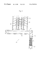
- FIGS. 2 a , 2 b a representation of a first embodiment of the device according to this invention, shown in cross section (FIG. 2 a longitudinal cross section; FIG. 2 b cross section through the container);
- FIG. 3 a partial cross section through the adsorbant/absorbant collection device according to line I—I in FIG. 2 a;
- FIGS. 4 a , 4 b an additional embodiment of the invention with prone container in two longitudinal cross sections shown in two mutually perpendicular planes;
- FIGS. 5 a , 5 b an additional embodiment of the invention with prone container in the representation according to FIGS. 4 a , 4 b ;
- FIGS. 6 a , 6 b an additional, simplified embodiment of the invention with prone container in the representation according to FIGS. 4 a , 4 b , 5 a and 5 b.
- the overall system illustrated in FIG. 1 for cleaning of flue gas consists essentially of a precooler 1 , and the raw gas to be cleaned is sent to it through a valve 3 in the direction of the arrow and of the actual device 5 for cleaning of the flue gas, with a solids separator 7 outlet connected to it.
- the cleaned flue gas is then output through a smokestack 9 .
- the cleaning power can also be increased, or the cleaning of the gases can be improved by a series circuiting of several devices 5 .
- FIG. 1 The path of the gas through the system in normal operation is indicated in FIG. 1 by the thick, solid lines and arrows.
- the thin, solid lines represent paths which ensure the operational dependability in case of malfunction of one or more components.
- the line 11 and the associated valve 13 pertain to an emergency bypass, with which the entire system can be bridged and the raw gas can be sent directly to the stack 9 .
- the device 5 which is illustrated in FIG. 2 a , is composed of a container 31 and the raw gas is supplied to it in the direction of the arrow through an inlet opening 33 .
- the cleaned, raw gas is sent through an outlet opening 35 in the lower region of the container 31 and to the solids separator 7 (FIG. 1 ), which can be designed, for example, as a cloth filter.
- Dry or quasi-dry dust-like or powdered adsorbant/absorbant can be supplied to the container 31 through an adsorbant/absorbant device 37 .
- the adsorption and/or absorption of harmful pollutants in the raw gas is improved by the adsorbant/absorbant particles, when they have a certain moisture, in the adsorbant/absorbant supply device 37 under admixing of the adsorbant/absorbant, water is added until a predefined moisture content is achieved.
- this can take place independently in the form of a closed control circuit, whereby the moisture content can be selected depending on certain parameters, for example, the temperature of the supplied raw gas.
- the moisture content of the adsorbant/absorbant before the inlet into the interior of the container 31 can be increased, for example, up to the limit of the presence of a dust-like structure.
- the adsorbant/absorbant in this case is still in dust-like or powder form, so that as before, a large, active surface area is available for the cleaning.
- the longitudinal axis of the container 31 there are several (in the illustrated example, four) shafts 39 which run parallel to the longitudinal axis of the container.
- the shafts are rotated by means of driven electromotors 41 which are provided at the top side of the container 31 .
- chains 43 are provided on the shafts 39 inside the container. These chains hang down due to gravity when the shafts are stopped, and extend due to the action of centrifugal force, outward when the shafts rotate.
- any other kind of flexible turbulence elements can be used, for example, cables.
- chains offer the advantage that due to the leads in the chain links, a more intensive swirling can be obtained.
- smaller, rigid or flexible elements can be attached to the flexible turbulence elements (in a manner not illustrated) to increase the air resistance.
- the container 31 can have a wall 31 a whose inside wall has several partly cylindrical regions 31 b .
- the four shafts are then arranged, as illustrated in FIG. 2 b , preferably in such a manner that they reside in the axis of the partly cylindrical regions 31 b.
- each shaft 39 can be reversed at certain time intervals, or the speed of rotation can be changed.
- a change in shape of the flexible turbulence elements 43 will be obtained, so that the potentially deposited layers will be blasted off.
- the shafts 39 can have a synchronized operation, with regard to their rotational motion, so that the chains 43 do not beat against each other in the middle of the container.
- this synchronization can also be ceased for a short time, so that the chains will clean each other by means of mutual impacts.
- the chains can be uniformly distributed, for example, so that to avoid imbalances or flexure of the shafts, a symmetrical arrangement of chains in a plane perpendicular to the shaft is preferred. As illustrated in FIG. 2 b , for example, four chains can be provided in one plane.
- the chains 43 can also have different lengths in order to achieve the desired swirling effects.
- the chains can be arranged in groups in the axial direction, whereby zones of large turbulence will alternate with calmer zones. In particular in the transition layers, high relative speeds will be produced between the adsorbant/absorbant particles and the gas.
- a collection device 45 for the adsorbant/absorbant which comprises a conveyance device 47 —as clearly indicated in FIG. 3 —which supplies the adsorbant/absorbant collecting on the conveyor chain 49 (partly laden with pollutants) to a collection shaft 51 .
- the conveyor chain 49 extends preferably across the entire bottom surface of the container 31 .
- an additional conveyance device 53 which uses an additional conveyor chain 55 to again supply the adsorbant/absorbant to the adsorbant/absorbant inlet device 37 .
- the latter can comprise, for example, a conveyor path 57 designed as a bucket conveyor.
- the adsorbant/absorbant supply device 37 is composed of an inlet device 58 for fresh material, that is, fresh adsorbant/absorbant.
- This fresh material supply device can, as shown in FIGS. 1 and 2 a , supply the fresh material to the underside of the conveyor path 57 from an adsorbant/absorbant silo 62 (FIG. 1 ).
- the inlet of fresh material can also occur at any location between the adsorbant/absorbant inlet opening and the adsorbant/absorbant collection device 45 .
- the quantity of fresh material supplied to the adsorbant/absorbant already present in the cycle can be controlled or regulated as a function of particular parameters, e.g., the quantity of pollutants to be adsorbed or absorbed.
- adsorbant/absorbant supply device 37 water up to a particular moisture content, can be added to the adsorbant/absorbant already present in the cycle, in the manner described above.
- a fraction of the produced reaction product corresponding to the inlet and outlet quantity, is sluiced out of the adsorbant/absorbant cycle from the collection shaft 51 —as illustrated in FIG. 3 —by means of an outlet device 59 , which can be composed of a conveyor worm, for instance, and then sent to the residual silo 61 (FIG. 1) for disposal.
- the quantity of adsorbant/absorbant present in the cycle will thus be kept essentially constant.
- the adsorbant/absorbant layer present in the collection shaft 51 Due to the adsorbant/absorbant layer present in the collection shaft 51 , at the same time it is possible to maintain the pressure difference between the inlet opening 33 and the outlet opening 35 for the gas and in this manner to prevent the raw gas from moving via the adsorbant/absorbant inlet device 37 and the collection shaft 51 in the direction of the outlet opening 35 , without having passed through the correct cleaning procedure.
- adsorbant/absorbant supply device 37 and of the adsorbant/absorbant collection device 45 will ensure the desired, high-level adsorbant/absorbant throughput through the container 31 .
- these elements can also be used with known containers 31 .
- each adsorbant/absorbant particle passes several times through the container 31 and contributes repeatedly to a cleaning of the gas.
- the adsorbant/absorbant thus remains—given an appropriate total quantity of adsorbant/absorbant within the cycle—for a relatively long time in the cycle (two days and more), so that the additional advantage is obtained that resulting reaction products will be oxidized by the residual oxygen present in the gas and due to the moisture.
- calcium sulfite (CaSO 3 ) present in the adsorbant/absorbant will be oxidized to calcium sulfate (CaSO 4 ). This will occur right within the adsorbant/absorbant cycle. An outlet-connected step for oxidation of the spent adsorbant/absorbant removed by the outlet device 59 is thus not necessary.
- FIG. 4 a and 4 b show additional design example of the invention presented in FIG. 4 a and 4 b , where we will discuss solely the differences to the design example according to FIGS. 2 and 3.
- essential parts of the collection device 45 for the adsorbant/absorbant and the adsorbant/absorbant supply device 37 remain in principle unchanged.
- the container 31 of the device 5 is positioned prone, whereby the shafts 39 are positioned perpendicular to the longitudinal axis of the container in a vertical direction. The propulsion of the shafts remains essentially unchanged.
- the bearing of the shafts can be placed outside of the container interior, in particular also at the underside, and thus the bearings are protected against aggressive gases.
- the inlet opening 33 for the raw gas initially expands up to the entire cross section of the container 31 , so that a reduction in the rate of flow will be achieved. In this manner, the gases to be cleaned remain within the container 31 , which contributes to an increase in the cleaning effect.
- the chains 43 provided on the shafts 39 are positioned essentially at equidistant, axial intervals around the shafts and are distributed along the perimeter of the shaft, so that an imbalance will be avoided. But of course, in this design as well, in each plane there are several, for example, four, chains so that in each plane perpendicular to the shaft, an imbalance will be precluded.
- the container interior walls running perpendicular to the shafts can have along these interior walls (as explained in association with FIGS. 6 a and 2 b flow control elements (not illustrated) which prevent an unhindered gas flow in the direction of the gas outlet openings 35 .
- a collector device 45 for the adsorbant/absorbant In the bottom wall of the container 31 , in the vicinity of the gas outlet opening 35 , there is a collector device 45 for the adsorbant/absorbant.
- This device is composed of a conveyor device 47 which extends over the entire width of the container 31 .
- the collection device 45 is unchanged, likewise also the adsorbant/absorbant inlet device 37 .
- the representation of the cycle for the adsorbant/absorbant was omitted.
- the supplied adsorbant/absorbant particles repeatedly settle on the bottom wall and are repeatedly swirled up.
- the adsorbant/absorbant particles are carried along by the gas stream in the direction of the gas outlet opening 35 . Since in the rear region of the container 31 , i.e., in the region of the collection device 45 no more rotating shafts are provided, the adsorbant/absorbant particles mostly settle onto the conveyor chain of the collector device 45 .
- FIGS. 5 a and 5 b differs from the embodiment according to FIGS. 4 a and 4 b solely in that the shafts 39 are positioned horizontal and perpendicular to the longitudinal axis of the container 31 .
- the reader is referred to the above description.
- the collection device 45 for the adsorbant/absorbant is provided with a longer conveyor chain which is driven until the adsorbant/absorbant located on the conveyor chain is moved in the direction of the container end, and from there is conveyed to the underside of the conveyor chain in the direction of the collection shaft.
- concentration of the adsorbant/absorbant particles in the region of the shafts 39 which are located above the conveyor chain, is reduced with respect to the adsorbant/absorbant concentration in the front region of the container 31 . In this manner the fraction of adsorbant/absorbant particles carried off by the gas through the gas outlet opening 35 will be reduced.
- the chains 43 Due to the horizontal formation of the shafts 39 , the chains 43 at low shaft speed, for example, during stoppage of the device, will wind up around the shafts so that an unhindered access to the interior region of the container 31 is possible. But at a higher rotational velocity, the chains will unwind due to the centrifugal force, so that in this design as well, an optimum swirling of the gas adsorbant/absorbant mixture is assured.
- FIGS. 6 a and 6 b show a simplified embodiment of the invention with likewise prone container 31 .
- the shafts 39 are again arranged horizontal and perpendicular to the longitudinal axis of the container 31 .
- only a single row of shafts 39 is provided, whereby the chains are designed only to be long enough so that contact of the chains with each other is prevented. Consequently, a synchronization of the drive units for the shafts 39 can be omitted.
- chains 43 are axially spaced apart along respective shaft 39 such that the chains are attached to the shaft along a helical line around the perimeter of the respective shaft.
- a conveyor chain of the collector device 45 for the adsorbant/absorbant extends over the entire lower inner wall. As illustrated in FIG. 6 a , this chain can be driven either so that the upper side of the conveyor chain will move in the direction of the gas outlet opening 35 , so that the adsorbant/absorbant will be promoted between the underside of the conveyor chain and the container inner wall in the direction of the collector shaft of the device 45 .
- this chain can be driven either so that the upper side of the conveyor chain will move in the direction of the gas outlet opening 35 , so that the adsorbant/absorbant will be promoted between the underside of the conveyor chain and the container inner wall in the direction of the collector shaft of the device 45 .
- the conveyor chain can also be driven oppositely, so that the adsorbant/absorbant which settles onto the conveyor chain is repeatedly moved in the direction of the gas inlet opening 33 .
- the speed of the conveyor chain will then have to be selected as greater than the average speed of motion of the adsorbant/absorbant particles in the gas stream.
- the dwell time of the adsorbant/absorbant particles in the interior of the container 31 can be increased.
- flow control elements 63 can be provided below the conveyor chain of the adsorbant/absorbant collection device 45 ; these flow control elements are located in regions between the outer circular paths of the chains 43 and exert a function corresponding to the circular-cylindrical regions 31 b ′ of the upper wall.
- additional flow control elements 65 are provided on the lateral, inside walls of the container 31 , which prevent the gas with little or no swirling, from moving along these paths from the inlet opening 33 to the outlet opening 35 .
Landscapes
- Chemical & Material Sciences (AREA)
- Engineering & Computer Science (AREA)
- Chemical Kinetics & Catalysis (AREA)
- Environmental & Geological Engineering (AREA)
- General Chemical & Material Sciences (AREA)
- Oil, Petroleum & Natural Gas (AREA)
- Analytical Chemistry (AREA)
- Biomedical Technology (AREA)
- Health & Medical Sciences (AREA)
- Organic Chemistry (AREA)
- Treating Waste Gases (AREA)
- Separation Of Particles Using Liquids (AREA)
- Filtering Of Dispersed Particles In Gases (AREA)
- Incineration Of Waste (AREA)
- Gas Separation By Absorption (AREA)
- General Preparation And Processing Of Foods (AREA)
- Separating Particles In Gases By Inertia (AREA)
Applications Claiming Priority (3)
| Application Number | Priority Date | Filing Date | Title |
|---|---|---|---|
| DE19530497A DE19530497C1 (de) | 1995-08-18 | 1995-08-18 | Vorrichtung zur Reinigung von Rauchgas |
| DE19530497 | 1995-08-18 | ||
| PCT/DE1996/001542 WO1997006874A1 (de) | 1995-08-18 | 1996-08-19 | Vorrichtung zur reinigung von rauchgas |
Publications (1)
| Publication Number | Publication Date |
|---|---|
| US6177052B1 true US6177052B1 (en) | 2001-01-23 |
Family
ID=7769857
Family Applications (1)
| Application Number | Title | Priority Date | Filing Date |
|---|---|---|---|
| US09/011,731 Expired - Lifetime US6177052B1 (en) | 1995-08-18 | 1996-02-19 | Device for cleaning of flue gas |
Country Status (12)
| Country | Link |
|---|---|
| US (1) | US6177052B1 (hu) |
| EP (2) | EP0800854B1 (hu) |
| JP (1) | JP3881380B2 (hu) |
| KR (1) | KR100458387B1 (hu) |
| AT (2) | ATE196101T1 (hu) |
| AU (1) | AU7277696A (hu) |
| CZ (1) | CZ294508B6 (hu) |
| DE (4) | DE19530497C1 (hu) |
| ES (1) | ES2152044T3 (hu) |
| HU (1) | HU223032B1 (hu) |
| PL (1) | PL184000B1 (hu) |
| WO (1) | WO1997006874A1 (hu) |
Cited By (9)
| Publication number | Priority date | Publication date | Assignee | Title |
|---|---|---|---|---|
| US6672755B1 (en) * | 1997-07-19 | 2004-01-06 | Klean Earth Environmental Company Inc. | Equipment for mixing a powder with a liquid |
| WO2006109336A1 (fr) * | 2005-04-14 | 2006-10-19 | Luigi Pietro Della Casa | Pulverisateur-melangeur a rouleaux, pour pulveriser et melanger des fluides |
| US8172448B1 (en) | 2009-09-03 | 2012-05-08 | Astec, Inc. | Method and apparatus for adapting asphalt dryer/mixer to minimize asphalt build-up |
| FR2982175A1 (fr) * | 2011-11-07 | 2013-05-10 | Sita Bioenergies | Installation d'epuration de biogaz, procede de traitement de biogaz et utilisation de machefers pour un tel traitement. |
| US20170028366A1 (en) * | 2015-07-28 | 2017-02-02 | Douglas G. Pullman | Mixing apparatus and system |
| CN107398161A (zh) * | 2017-09-11 | 2017-11-28 | 西安热工研究院有限公司 | 燃煤电站锅炉烟气水分回收及细颗粒物脱除的系统及方法 |
| US10414693B2 (en) * | 2017-07-24 | 2019-09-17 | Carmeuse North America | Composition for treatment of flue gas waste products |
| CN110772967A (zh) * | 2019-11-14 | 2020-02-11 | 西安交通大学 | 一种自适应风量波动的旋转烟气半干法脱硫装置 |
| CN113529898A (zh) * | 2021-08-23 | 2021-10-22 | 江苏银中建设有限公司 | 一种市政污水收集系统 |
Families Citing this family (7)
| Publication number | Priority date | Publication date | Assignee | Title |
|---|---|---|---|---|
| DE29807889U1 (de) * | 1998-05-02 | 1998-07-30 | Rob Ing Rudolf Ohlmann Techn B | Einrichtung zum Einbringen eines Adsorptionsmittels in ein Abgas |
| DE102006038443B3 (de) * | 2006-08-16 | 2007-09-13 | Andreas Friedl | Vorrichtung zur Reinigung von Rauchgas |
| CN101745308B (zh) * | 2008-12-17 | 2012-08-29 | 贵阳铝镁设计研究院有限公司 | 一种赤泥脱硫塔 |
| DE102009043120B4 (de) | 2009-09-25 | 2014-05-08 | Nederman Filtration GmbH | Verfahren und Vorrichtung zur Reinigung von Rauch- und Abgasen |
| CN114618291A (zh) * | 2020-12-10 | 2022-06-14 | 西南科技大学 | 生石灰的干法消化与烟气脱硫一体化工艺 |
| CN113088339B (zh) * | 2021-03-31 | 2023-02-07 | 重庆朗福环保科技有限公司 | 一种高炉煤气精脱硫装置 |
| CN115282803B (zh) * | 2022-07-28 | 2024-03-22 | 陕西双和建材科技有限公司 | 一种混凝土减水剂配制装置 |
Citations (10)
| Publication number | Priority date | Publication date | Assignee | Title |
|---|---|---|---|---|
| US870748A (en) * | 1907-08-30 | 1907-11-12 | Selg Brewery Apparatus Co | Stirrer for mash-tubs. |
| US1906735A (en) * | 1929-10-17 | 1933-05-02 | Bradley Fitch Co | Treating chamber |
| US3223290A (en) * | 1963-12-23 | 1965-12-14 | Schuld Leo Alois | Bottom discharge container with agitator |
| US3807702A (en) * | 1971-06-21 | 1974-04-30 | Huber Corp J M | An improved apparatus for encapsulating a finely divided clay within an organic polymeric material |
| US4289579A (en) * | 1977-12-12 | 1981-09-15 | Forsberg G L K | Method for treating a bulk material with a fluid |
| US4337583A (en) * | 1981-05-14 | 1982-07-06 | Harris Kenneth R | Apparatus and method for drying a substance |
| EP0203430A1 (de) * | 1985-05-07 | 1986-12-03 | Phoenix Gesellschaft für Rauchgasreinigung und Umwelttechnik mbH | Verfahren und Anlage zur Reinigung von Rauchgas |
| US4755061A (en) * | 1987-11-04 | 1988-07-05 | Phillips Petroleum Company | Proportional feeder for particulate solids |
| EP0342559A1 (de) * | 1988-05-17 | 1989-11-23 | Paul Christian | Vorrichtung zum Abscheiden von Stäuben und/oder sauren Schadstoffen aus Gasen |
| US5104524A (en) * | 1987-06-01 | 1992-04-14 | Deutsche Gesellschaft Fur Wiederaufarbeitung Von Kernbrennstoffen Gmbh | Apparatus for washing a solvent in the reprocessing of irradiated nuclear fuels |
Family Cites Families (8)
| Publication number | Priority date | Publication date | Assignee | Title |
|---|---|---|---|---|
| CH596325A5 (hu) * | 1972-11-03 | 1978-03-15 | Macdermid Inc | |
| US3976747A (en) * | 1975-06-06 | 1976-08-24 | The United States Of America As Represented By The United States Energy Research And Development Administration | Modified dry limestone process for control of sulfur dioxide emissions |
| GB1547945A (en) * | 1975-10-09 | 1979-07-04 | Pfizer | Process and apparatus for reducing the so2 content of a hot fiue gas |
| US4542000A (en) * | 1984-01-30 | 1985-09-17 | Efb, Inc. | Method for treating gas streams |
| DE3638391A1 (de) * | 1986-11-11 | 1988-05-26 | Harry Wettermann | Vorrichtung zum entfernen von schadgasen und staeuben aus einem abgasstrom |
| DE9011407U1 (hu) * | 1990-08-04 | 1990-10-25 | Raab, Karl, 8090 Hafenham, De | |
| US5094604A (en) * | 1990-12-19 | 1992-03-10 | Oil-Dri Corporation Of America | Apparatus for making granular absorbent from fibrous materials |
| WO1994007591A1 (en) * | 1992-09-25 | 1994-04-14 | Niro A/S | Process of producing calcium hydroxide for absorption |
-
1995
- 1995-08-18 DE DE19530497A patent/DE19530497C1/de not_active Expired - Lifetime
-
1996
- 1996-02-19 US US09/011,731 patent/US6177052B1/en not_active Expired - Lifetime
- 1996-08-19 CZ CZ1998466A patent/CZ294508B6/cs not_active IP Right Cessation
- 1996-08-19 ES ES96934359T patent/ES2152044T3/es not_active Expired - Lifetime
- 1996-08-19 HU HU9901173A patent/HU223032B1/hu not_active IP Right Cessation
- 1996-08-19 JP JP50883797A patent/JP3881380B2/ja not_active Expired - Fee Related
- 1996-08-19 AT AT96934359T patent/ATE196101T1/de active
- 1996-08-19 DE DE59605852T patent/DE59605852D1/de not_active Expired - Lifetime
- 1996-08-19 EP EP97109512A patent/EP0800854B1/de not_active Revoked
- 1996-08-19 WO PCT/DE1996/001542 patent/WO1997006874A1/de active IP Right Grant
- 1996-08-19 PL PL96325165A patent/PL184000B1/pl unknown
- 1996-08-19 KR KR10-1998-0701151A patent/KR100458387B1/ko not_active IP Right Cessation
- 1996-08-19 EP EP96934359A patent/EP0874681B1/de not_active Expired - Lifetime
- 1996-08-19 DE DE29624272U patent/DE29624272U1/de not_active Ceased
- 1996-08-19 AU AU72776/96A patent/AU7277696A/en not_active Abandoned
- 1996-08-19 DE DE59608373T patent/DE59608373D1/de not_active Revoked
- 1996-08-19 AT AT97109512T patent/ATE209953T1/de not_active IP Right Cessation
Patent Citations (10)
| Publication number | Priority date | Publication date | Assignee | Title |
|---|---|---|---|---|
| US870748A (en) * | 1907-08-30 | 1907-11-12 | Selg Brewery Apparatus Co | Stirrer for mash-tubs. |
| US1906735A (en) * | 1929-10-17 | 1933-05-02 | Bradley Fitch Co | Treating chamber |
| US3223290A (en) * | 1963-12-23 | 1965-12-14 | Schuld Leo Alois | Bottom discharge container with agitator |
| US3807702A (en) * | 1971-06-21 | 1974-04-30 | Huber Corp J M | An improved apparatus for encapsulating a finely divided clay within an organic polymeric material |
| US4289579A (en) * | 1977-12-12 | 1981-09-15 | Forsberg G L K | Method for treating a bulk material with a fluid |
| US4337583A (en) * | 1981-05-14 | 1982-07-06 | Harris Kenneth R | Apparatus and method for drying a substance |
| EP0203430A1 (de) * | 1985-05-07 | 1986-12-03 | Phoenix Gesellschaft für Rauchgasreinigung und Umwelttechnik mbH | Verfahren und Anlage zur Reinigung von Rauchgas |
| US5104524A (en) * | 1987-06-01 | 1992-04-14 | Deutsche Gesellschaft Fur Wiederaufarbeitung Von Kernbrennstoffen Gmbh | Apparatus for washing a solvent in the reprocessing of irradiated nuclear fuels |
| US4755061A (en) * | 1987-11-04 | 1988-07-05 | Phillips Petroleum Company | Proportional feeder for particulate solids |
| EP0342559A1 (de) * | 1988-05-17 | 1989-11-23 | Paul Christian | Vorrichtung zum Abscheiden von Stäuben und/oder sauren Schadstoffen aus Gasen |
Cited By (13)
| Publication number | Priority date | Publication date | Assignee | Title |
|---|---|---|---|---|
| US6672755B1 (en) * | 1997-07-19 | 2004-01-06 | Klean Earth Environmental Company Inc. | Equipment for mixing a powder with a liquid |
| WO2006109336A1 (fr) * | 2005-04-14 | 2006-10-19 | Luigi Pietro Della Casa | Pulverisateur-melangeur a rouleaux, pour pulveriser et melanger des fluides |
| US20080165614A1 (en) * | 2005-04-14 | 2008-07-10 | Luigi Pietro Della Casa | Roller-Type Sprayer-Mixer for Spraying and Mixing Fluids |
| US7927007B2 (en) | 2005-04-14 | 2011-04-19 | Luigi Pietro Della Casa | Roller-type sprayer-mixer for spraying and mixing fluids |
| US8172448B1 (en) | 2009-09-03 | 2012-05-08 | Astec, Inc. | Method and apparatus for adapting asphalt dryer/mixer to minimize asphalt build-up |
| FR2982175A1 (fr) * | 2011-11-07 | 2013-05-10 | Sita Bioenergies | Installation d'epuration de biogaz, procede de traitement de biogaz et utilisation de machefers pour un tel traitement. |
| US20170028366A1 (en) * | 2015-07-28 | 2017-02-02 | Douglas G. Pullman | Mixing apparatus and system |
| US10507443B2 (en) * | 2015-07-28 | 2019-12-17 | Surface To Surface Inc. | Mixing apparatus and system |
| US11413588B2 (en) | 2015-07-28 | 2022-08-16 | Surface To Surface Inc. | Mixing apparatus and system |
| US10414693B2 (en) * | 2017-07-24 | 2019-09-17 | Carmeuse North America | Composition for treatment of flue gas waste products |
| CN107398161A (zh) * | 2017-09-11 | 2017-11-28 | 西安热工研究院有限公司 | 燃煤电站锅炉烟气水分回收及细颗粒物脱除的系统及方法 |
| CN110772967A (zh) * | 2019-11-14 | 2020-02-11 | 西安交通大学 | 一种自适应风量波动的旋转烟气半干法脱硫装置 |
| CN113529898A (zh) * | 2021-08-23 | 2021-10-22 | 江苏银中建设有限公司 | 一种市政污水收集系统 |
Also Published As
| Publication number | Publication date |
|---|---|
| HUP9901173A3 (en) | 2000-03-28 |
| HU223032B1 (hu) | 2004-03-01 |
| ES2152044T3 (es) | 2001-01-16 |
| DE59605852D1 (de) | 2000-10-12 |
| EP0800854A2 (de) | 1997-10-15 |
| EP0874681B1 (de) | 2000-09-06 |
| JP3881380B2 (ja) | 2007-02-14 |
| JPH11511069A (ja) | 1999-09-28 |
| WO1997006874A1 (de) | 1997-02-27 |
| DE19530497C1 (de) | 1996-12-05 |
| DE29624272U1 (de) | 2001-08-09 |
| KR100458387B1 (ko) | 2005-06-01 |
| ATE209953T1 (de) | 2001-12-15 |
| KR19990037672A (ko) | 1999-05-25 |
| DE59608373D1 (de) | 2002-01-17 |
| PL184000B1 (pl) | 2002-08-30 |
| EP0800854B1 (de) | 2001-12-05 |
| EP0800854A3 (de) | 1998-04-01 |
| HUP9901173A2 (hu) | 1999-08-30 |
| EP0874681A1 (de) | 1998-11-04 |
| CZ294508B6 (cs) | 2005-01-12 |
| PL325165A1 (en) | 1998-07-06 |
| AU7277696A (en) | 1997-03-12 |
| ATE196101T1 (de) | 2000-09-15 |
| CZ46698A3 (cs) | 1998-08-12 |
Similar Documents
| Publication | Publication Date | Title |
|---|---|---|
| US6177052B1 (en) | Device for cleaning of flue gas | |
| US4273750A (en) | Flue gas desulfurization apparatus and method | |
| CN1076980C (zh) | 用来混合颗粒材料和液体的设备 | |
| AU621429B2 (en) | Process and apparatus for the dry removal of polluting material from gas streams | |
| HU221182B1 (en) | Improved entrainment separator for high velocity gases and reheating of scrubber gases | |
| US4060587A (en) | Gaseous and liquid reactant treatment | |
| US5480624A (en) | Method for purification of waste gases | |
| FI84435B (fi) | Foerfarande och anordning foer rengoering av foeroreningar innehaollande gaser. | |
| JP2002535126A (ja) | ダイオキシンなどの,有害物質が含まれる有害ガスの浄化方法及び装置 | |
| US4452765A (en) | Method for removing sulfur oxides from a hot gas | |
| US5647892A (en) | Method for acid gas emission control | |
| MXPA97003098A (en) | Improved control of gas emission ac | |
| CN201572600U (zh) | 一种垃圾焚烧烟气净化干法脱酸系统 | |
| CN101632894B (zh) | 半干式烟气脱硫的方法及装置 | |
| US3807962A (en) | Cleaning device in absorption apparatus | |
| SE505579C2 (sv) | Sätt att avskilja stoft från varma processgaser | |
| JPS62125821A (ja) | ガス処理装置 | |
| US4256045A (en) | Apparatus and method for treating a gas with a liquid | |
| CN201231132Y (zh) | 半干式烟气脱硫装置 | |
| CN205760578U (zh) | 离心喷淋塔 | |
| JP2695988B2 (ja) | 廃ガスの精製法 | |
| JPH06170157A (ja) | 排ガスの処理方法 | |
| CN210448716U (zh) | 一种高效烟气气动乳化除尘、脱硫装置 | |
| RU2104757C1 (ru) | Способ очистки газообразных отходов | |
| GB2144650A (en) | Gas scrubber |
Legal Events
| Date | Code | Title | Description |
|---|---|---|---|
| AS | Assignment |
Owner name: FHW-BRENNTECHNIK, GMBH, GERMANY Free format text: ASSIGNMENT OF ASSIGNORS INTEREST;ASSIGNOR:FRIEDL, ANDREAS;REEL/FRAME:010739/0226 Effective date: 20000229 |
|
| STCF | Information on status: patent grant |
Free format text: PATENTED CASE |
|
| AS | Assignment |
Owner name: FHW-BRENNTECHNIK GMBH, GERMANY Free format text: ASSIGNMENT OF ASSIGNORS INTEREST;ASSIGNOR:WEICHS, ELISABETH;REEL/FRAME:011700/0391 Effective date: 20010213 |
|
| FPAY | Fee payment |
Year of fee payment: 4 |
|
| AS | Assignment |
Owner name: M+W ZANDER FACILITY ENGINEERING PTE. LTD., SINGAPO Free format text: ASSIGNMENT OF ASSIGNORS INTEREST;ASSIGNOR:FHW-BRENNTECHNIK GMBH;REEL/FRAME:016570/0919 Effective date: 20050701 |
|
| FPAY | Fee payment |
Year of fee payment: 8 |
|
| AS | Assignment |
Owner name: DANTHERM FILTRATION GMBH, GERMANY Free format text: ASSIGNMENT OF ASSIGNORS INTEREST;ASSIGNOR:M+W ZANDER FACILITY ENGINEERING PTE. LTD.;REEL/FRAME:022240/0562 Effective date: 20071211 |
|
| FPAY | Fee payment |
Year of fee payment: 12 |