US6170445B1 - Electromagnetic actuating system of internal combustion engine - Google Patents
Electromagnetic actuating system of internal combustion engine Download PDFInfo
- Publication number
- US6170445B1 US6170445B1 US09/441,336 US44133699A US6170445B1 US 6170445 B1 US6170445 B1 US 6170445B1 US 44133699 A US44133699 A US 44133699A US 6170445 B1 US6170445 B1 US 6170445B1
- Authority
- US
- United States
- Prior art keywords
- armature
- internal combustion
- combustion engine
- electromagnet
- valve
- Prior art date
- Legal status (The legal status is an assumption and is not a legal conclusion. Google has not performed a legal analysis and makes no representation as to the accuracy of the status listed.)
- Expired - Fee Related
Links
Images


Classifications
-
- F—MECHANICAL ENGINEERING; LIGHTING; HEATING; WEAPONS; BLASTING
- F01—MACHINES OR ENGINES IN GENERAL; ENGINE PLANTS IN GENERAL; STEAM ENGINES
- F01L—CYCLICALLY OPERATING VALVES FOR MACHINES OR ENGINES
- F01L9/00—Valve-gear or valve arrangements actuated non-mechanically
- F01L9/20—Valve-gear or valve arrangements actuated non-mechanically by electric means
Definitions
- the present invention relates to an electromagnetic actuating system of an internal combustion engine, and particularly to an electromagnetic actuating system of an internal combustion engine which actuates an intake valve or an exhaust valve by cooperation of an electromagnetic force generated by an electromagnet and a resilient force generated by a spring.
- An upper electromagnet and an upper spring are disposed above the armature, and a lower electromagnet and a lower spring are disposed below the armature.
- the armature is held at a neutral position between the upper and lower electromagnets by the upper and lower springs.
- Each of the upper and lower electromagnets generates an electromagnet force which attracts the armature by being supplied with an exciting current.
- the movable part can be moved toward the upper electromagnet by supplying an exciting current to the upper electromagnet.
- the movable part can be moved toward the lower electromagnet by supplying an exciting current to the lower electromagnet.
- the intake valve or the exhaust valve it is possible to actuate the intake valve or the exhaust valve to be closed and opened by alternately supplying exciting currents to the upper and lower electromagnets at appropriate timings.
- the movable part when the movable part is in a fully closed position or a fully opened position, the movable part can promptly start being actuated in response to a request by cooperation of the electromagnetic force generated by the upper or lower electromagnet and a resilient force generated by the upper or lower spring.
- the movable part when power supply to the solenoid valve is shut off, the movable part is held at a neutral position between the fully closed position and the fully opened position since neither the upper electromagnet nor the lower electromagnet is energized. In this state, the armature is spaced away from both the upper and lower electromagnets and resilient forces of the upper and lower springs exerted on the armature are balanced.
- exciting currents are alternately supplied to the upper and lower electromagnets with a period corresponding to a natural vibration period of the movable part when the internal combustion engine is started.
- the movable part can be moved from the neutral position to the fully closed position or the fully opened position by a resonance phenomenon of the movable part.
- the above-mentioned process of, when the engine is started, moving the movable part to the fully closed or opened position by exciting a natural vibration of the movable part is referred to as an initial actuation.
- Japanese Laid-Open Patent Application No. 10-138110 discloses a solenoid valve which can maintain the movable part in the fully closed position without performing the initial actuation.
- This solenoid valve includes a solenoid which is provided to the upper spring at one end thereof opposite to the armature.
- the solenoid When the solenoid is not energized, the upper spring is upwardly retracted. In this state, the armature is in contact with the upper electromagnet.
- the solenoid when the solenoid is energized, the upper spring is downwardly pressed toward the armature by the solenoid. In this state, the armature is held in the neutral position.
- the movable part when the engine is operating, the movable part must be actuated by the upper and lower electromagnets with the neutral position being a center of movement of the movable part.
- the solenoid when the engine is operating, it is necessary to energize the solenoid so as to maintain a state where the upper spring is pressed toward the armature, resulting in increased power consumption of the solenoid valve.
- an electromagnetic actuating system of an internal combustion engine comprising:
- an engine valve which functions as an intake valve or an exhaust valve of the internal combustion engine
- an electromagnet which attracts the armature in a direction of movement of the engine valve by being supplied with a current
- a stop-time current controller which shuts off the current supplied to the electromagnet, after controlling the current supplied to the electromagnet until the armature is attracted to the electromagnet by the magnetic attracting force of the permanent magnet, when a request to stop the internal combustion engine is generated.
- the controller shuts off a current to the electromagnet after the armature is attracted by the permanent magnet to the electromagnet. Since the permanent magnet can exert a magnetic attracting force between the armature and the electromagnet, the state in which the armature is attracted by the permanent magnet to the electromagnet can be maintained while the electromagnet is being de-energized, that is, while the internal combustion engine is not operating. A position of the armature in the state where the armature is attracted to the electromagnet corresponds to the fully closed position or the fully opened position. Thus, the armature can be held in the fully closed position or the fully opened position when the internal combustion engine is started next time without performing the initial actuation.
- the invention it is possible to prevent an increase in an operating sound and power consumption of the system due to execution of the initial actuation. Additionally, since it is unnecessary to supply a current to the electromagnetic coils so as to hold the armature, electric power is not consumed while the internal combustion engine is not operating. Further, since the magnetic attracting force of the permanent magnet contributes to a force for attracting the armature toward the electromagnet while the internal combustion engine is operating, a current to be supplied to the electromagnet can be reduced. Thus, power consumption of the system can be further saved.
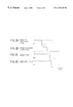
- FIG. 1 is a diagram showing a system of an embodiment of the present invention
- FIG. 2A is a time chart showing an example of an operation instruction current of an internal combustion engine
- FIG. 2B is a time chart showing an example of an attracting current supplied to an upper coil
- FIG. 2C is a time chart showing an example of an enable signal generated by an ECU
- FIG. 2D is a time chart showing an example of a change in an ON/OFF state of a power supply relay.
- FIG. 3 is a flowchart of a routine performed by the ECU in the present embodiment.
- FIG. 1 is a diagram showing a system of an embodiment according to the present invention.
- the system of the present embodiment includes a solenoid valve 10 which is provided to each of intake valves and exhaust valves of an internal combustion engine (hereinafter simply referred to as an engine).
- an engine an internal combustion engine
- the solenoid valve 10 has an engine valve 12 which functions as an intake valve or an exhaust valve.
- the engine valve 12 is disposed in a lower head 16 so that the engine valve 12 is exposed in a combustion chamber 14 of the engine.
- a port 18 is formed in the lower head 16 .
- An opening part of the port 18 into the combustion chamber 14 is provided with a valve seat 20 which is associated with the engine valve 12 .
- the port 18 communicates with the combustion chamber 14 when the engine valve 12 is released from the valve seat 20 , and the port 18 is disconnected from the combustion chamber 14 when the engine valve 12 is seated on the valve seat 20 .
- An upper head 22 is provided on a top of the lower head 16 .
- the engine valve 12 has a valve shaft 24 which extends upwardly.
- the valve shaft 24 is guided by a valve guide 26 so that the valve shaft 24 can move in an axial direction.
- the valve guide 26 is fixed in the lower head 16 .
- the lower head 16 is provided with a spring containing space 28 which is cylindrically formed and surrounds a substantially upper-half part of the valve shaft 24 .
- a lower retainer 30 is fixed to an upper end part of the valve shaft 24 .
- a lower spring 32 is disposed between the lower retainer 30 and a bottom face of the spring containing space 28 . The lower spring 32 exerts a resilient force on the lower retainer 30 so as to push the engine valve 12 in an upward direction, that is, in a valve closing direction.
- An armature shaft 34 is disposed coaxially with the valve shaft 24 .
- the armature shaft 34 is made of a non-magnetic material.
- a lower end face of the armature shaft 34 is in contact with an upper end face of the valve shaft 24 .
- An upper retainer 36 is fixed to an upper end part of the armature shaft 34 .
- a lower end of an upper spring 38 abuts on a top surface of the upper retainer 36 .
- a cylindrical upper cap 40 is provided around the upper spring 38 .
- An adjuster bolt 42 is screwed on a top part of the upper cap 40 .
- An upper end of the upper spring 38 is supported by a spring guide 44 which is interposed between the adjuster bolt 42 and the upper spring 38 .
- the upper spring 38 pushes the armature shaft 34 via the upper retainer 38 in a downward direction.
- the upper spring 38 pushes the engine valve 12 in a downward direction, that is, in a valve opening direction.
- An armature supporting part 34 a is formed on an outer circumferential surface of the armature shaft 34 at a substantially center position in an axial direction thereof.
- the armature supporting part 34 a projects outwardly in a radial direction of the armature shaft 34 .
- An armature 46 is fixed around the armature supporting part 34 a.
- the armature 46 is an annular member which is made of a soft magnetic material.
- An upper core 48 is disposed above the armature 46 , and a lower core 50 is disposed below the armature 46 .
- Each of the upper core 48 and the lower core 50 is a substantially cylindrical member made of a magnetic material.
- the upper core 48 and the lower core 50 are provided with through holes 48 a and 50 a, respectively, which go though the center parts thereof.
- An upper bush 52 is disposed in an upper end part of the through hole 48 a, and a lower bush 54 is disposed in a lower end part of the through hole 50 a.
- the armature shaft 34 extends through the through holes 48 a, 50 a and is guided by the upper bush 52 and the lower bush 54 so that the armature shaft 34 can move in the axial direction.
- the upper core 48 has a flange 48 b formed at an upper end part thereof.
- the lower core 50 has a flange 50 b formed at a lower end part thereof.
- the upper core 48 and the lower core 50 are fitted into a cylindrical part 22 a which is formed in the upper head 22 so that the flanges 48 b and 50 b abut on upper and lower faces of the upper head 22 , respectively.
- Annular recesses 48 c and 50 c are provided to faces of the upper core 48 and the lower core 50 , respectively, facing the armature 46 .
- An upper coil 56 and a lower coil 58 are contained in the annular recesses 48 c and 50 c, respectively.
- the upper coil 56 and the lower coil 58 are electrically connected to an actuating circuit 60 .
- the actuating circuit 60 is supplied with an enable signal for permitting or prohibiting an operation of the solenoid valve 10 and a control signal for controlling the solenoid valve 10 from an electronic control unit (hereinafter referred to as an ECU) 62 .
- the actuating circuit 60 supplies instruction currents to the upper coil 56 and the lower coil 58 in accordance with the control signal supplied from the ECU 62 when the enable signal is in an ON state. Power supply to the actuating circuit 60 can be turned on and off by a power supply relay 64 which is controlled by the ECU 62 .
- the upper core 48 is provided with an annular slit 48 d which extends from an upper face of the upper core 48 to an upper face of the annular recess 48 c.
- the lower core 50 is provided with an annular slit 50 d which extends from a lower face of the lower core 50 to a bottom face of the annular recess 50 c.
- An upper magnet 66 and a lower magnet 68 are contained in the annular slits 48 d and 50 d, respectively.
- Each of the upper magnet 66 and the lower magnet 68 is a permanent magnet having an annular shape which is radially magnetized (so that a radially inner side is an S pole and a radially outer side is an N pole, for example).
- the upper cap 40 has a flange 40 a which is provided at a lower end part thereof.
- the upper cap 40 is disposed so that the flange part 40 a covers the flange 48 b of the upper core 48 from above.
- a lower cap 70 is disposed on a lower face of the upper head 22 so that the lower cap 70 covers the flange 50 b of the lower core 50 from below.
- the flange 40 a of the upper cap 40 and the lower cap 70 are fixed to the upper head 22 by fixing bolts 72 so that the upper core 48 and the lower core 50 are fixed inside the upper head 22 with a predetermined spacing being formed therebetween.
- a neutral position of the armature 46 is adjusted by the above-mentioned adjuster bolt 42 so as to be at a central position between the upper core 48 and the lower core 50 .
- the upper coil 56 When the upper coil 56 is supplied with an instruction current which generates magnetic flux in a direction opposite to a direction of the magnetic flux generated by the upper magnet 66 in a state where the armature 46 is held in the fully closed position, the magnetic attracting force exerted between the armature 46 and the upper core 48 becomes smaller than the resilient force of the upper spring 38 . Thus, the armature 46 starts moving in a downward direction in FIG. 1 by being pressed by the upper spring 38 . When the armature 46 has reached a predetermined position, the lower coil 58 is supplied with an instruction current which generates magnetic flux in the same direction as magnetic flux generated by the lower magnet 68 . In this case, an attracting force which attracts the armature 46 toward the lower core 50 , that is, an attracting force which actuates the engine valve 12 in a downward direction in FIG. 1, is generated.
- the armature 46 When the above attracting force is exerted on the armature 46 , the armature 46 downwardly moves with the engine valve 12 against a resilient force of the lower spring 32 . In this case, since the magnet flux generated by the lower coil 58 and the magnet flux generated by the lower magnet 68 have the same direction as mentioned above, the attracting force which attracts the armature 46 toward the lower core 50 is increased by an extent corresponding to a magnitude of the magnetic flux generated by the lower magnet 68 . The engine valve 12 continues to move until the armature 46 comes into contact with the lower core 50 .
- a position of the armature 46 or the engine valve 12 in a state where the armature 46 is in contact with the lower core 50 is referred to as a fully opened position of the armature 46 or the engine valve 12 .
- the lower coil 58 When the armature 46 has reached the fully opened position, the lower coil 58 is de-energized. In this case, the attracting force generated by the lower coil 58 vanishes and only the magnetic attracting force generated by the lower magnet 68 is exerted between the armature 46 and the lower core 50 .
- the lower magnet 68 is so constructed that this magnetic attracting force is strong enough to maintain the armature 46 in contact with the lower core 50 against the resilient force of the lower spring 32 .
- the engine valve 12 and the armature 46 are maintained in the fully opened position after the lower coil 58 has been de-energized.
- the lower coil 58 When the lower coil 58 is supplied with an instruction current which generates magnetic flux in a direction opposite to a direction of the magnetic flux generated by the lower magnet 66 in a state where the armature 46 is held in the fully opened position, the attracting force exerted between the armature 46 and the lower core 50 becomes smaller than the resilient force of the lower spring 32 . Thus, the armature 46 starts moving in an upward direction in FIG. 1 by being pressed by the lower spring 32 . When the armature 46 has reached a predetermined position, the upper coil 56 is supplied with an instruction current which generates magnetic flux in the same direction as the magnetic flux generated by the upper magnet 66 . In this case, an attracting force which attracts the armature 46 toward the upper core 48 , that is, an attracting force which actuates the engine valve 12 in an upward direction in FIG. 1, is generated.
- the armature 46 When the above attracting force is exerted on the armature 46 , the armature 46 upwardly moves with the engine valve 12 against the resilient force of the upper spring 38 . In this case, since the magnet flux generated by the upper coil 56 and the magnet flux generated by the upper magnet 66 have the same direction as mentioned above, the attracting force which attracts the armature 46 toward the upper core 48 is increased by an extent corresponding to a magnitude of the magnetic flux generated by the upper magnet 66 . The engine valve 12 continues to move until the armature 46 comes into contact with the upper core 48 , that is, until the armature 46 reaches the fully closed position. The engine valve 12 and the armature 46 can be maintained in the fully closed position after the upper coil 56 is de-energized, as mentioned above.
- the instruction current which is supplied to the upper coil 56 or the lower coil 58 for releasing the armature 46 from the fully closed position or the fully opened position (that is, the instruction current which generates the magnetic flux in a direction which is opposite to the direction of the magnetic flux generated by the upper magnet 66 or the lower magnet 68 ) is referred to as a release current.
- the current which is supplied to the upper coil 56 or the lower coil 58 for attracting the armature 46 toward the fully closed position or the fully opened position that is, the instruction current which generates the magnetic flux in the same direction as the magnetic flux generated by the upper magnet 66 or the lower magnet 68 ) is referred to as an attracting current.
- the engine valve 12 can be actuated to be closed and opened in synchronization with a crank angle of the internal combustion engine by the ECU 62 supplying a control signal to the actuating circuit 60 based on the crank angle.
- a control for actuating the engine valve 12 in synchronization with the crank angle is referred to as a regular control.
- the armature 46 can be maintained in the fully closed position or the fully opened position by the magnetic attracting force generated by the upper magnet 66 or the lower magnet 68 without a necessity of energizing the upper coil 56 or lower coil 58 , as mentioned above. Additionally, since the magnetic attracting force generated by the upper magnet 66 or the lower magnet 68 is exerted on the armature 46 when the armature 46 is actuated toward the fully closed position or the fully opened position, it is possible to reduce the attracting currents required to be supplied to the upper coil 56 and the lower coil 58 . Thus, according to the present embodiment, it is possible to effectively lower power consumption of the solenoid valve 10 .
- the upper coil 56 and the lower coil 58 are alternately supplied with currents with a period corresponding to a natural vibration period of a spring-mass system constituted by movable parts including the armature 46 , the armature shaft 34 and the valve body 12 and the upper and lower springs 38 , 32 so that a natural vibration of the movable parts is excited.
- FIGS. 2A to 2 D are time charts of various control signals when a request to stop the engine is generated.
- FIG. 2A shows an operation instructing signal of the engine
- FIG. 2B shows an attracting current supplied to the upper coil 56 of the solenoid valve 10
- FIG. 2C shows an enable signal supplied to the actuating circuit 60
- FIG. 2D shows an ON/OFF signal supplied to the power supply relay 64 .
- the operation instructing signal is represented by a solid line and a dotted line for two cases where the request to stop the engine is generated at different timings.
- the operation instructing signal is switched to an OFF state at a time t 0 when the request to stop the engine is generated.
- the enable signal shown in FIG. 2C is maintained in an ON state.
- the upper coil 56 is supplied with an attracting current as shown in FIG. 2B so that the engine valve 12 is actuated toward the fully closed position.
- the enable signal is switch to an OFF state as shown in FIG. 2C so that the upper coil 56 and the lower coil 58 are prohibited from being energized.
- the enable signals corresponding to all of the solenoid valves 10 provided to the engine are set in an OFF state at a time t 4 , the power supply relay 64 is switched to an OFF state as shown in FIG. 2 D.
- the enable signal is immediately set in an OFF state.
- the engine valve 12 is actuated in accordance with the regular control until the engine valve 12 reaches the fully closed position after the request to stop the engine is generated, and the upper coil 56 and the lower coil 58 are prohibited from being supplied with currents after the engine valve 12 has been held in the fully closed position.
- the state where the engine valve 12 is held in the fully closed position can be maintained by the magnetic attracting force generated by the upper magnet 66 without supplying a current to the upper coil 56 .
- the engine valve 12 and the armature 46 are held in the fully closed position. Therefore, according to the present embodiment, it is possible to immediately start the regular control of the engine valve 12 when the engine is started without performing the initial actuation only by supplying the release current to the upper coil 56 at a valve-opening timing of the engine valve 12 .
- FIG. 3 shows a flowchart of a control routine performed by the ECU 62 so as to achieve the above-mentioned function.
- the routine shown in FIG. 3 is performed for each solenoid valve 10 at a time when the operation instructing signal of the engine is switched from an ON state to an OFF state.
- the process of step 100 is performed first.
- step 100 it is determined whether or not the engine valve 12 is held in the fully closed position. Such determination can be performed based on a state of the instruction current supplied to the upper coil 56 . For example, if supply of the attracting current to the upper coil 56 has been finished but the release current has not yet been supplied to the upper coil 56 , it can be determined that the engine valve 12 is held in the fully closed position. It is also possible to provide a sensor for detecting a position of the valve body 12 or the armature shaft 34 and to perform the determination in step 100 based on the detected position of the engine valve 12 or the armature shaft 34 . If it is determined that the engine valve 12 is not held in the fully closed position in step 100 , then the process of step 102 is performed.
- step 102 it is determined whether or not it is a timing to close the engine valve 12 according to the regular control. If it is not a timing to close the engine valve 12 , instruction currents to the upper coil 56 and the lower coil 58 are controlled in accordance with the regular control in step 103 , and then the process of step 102 is performed again. On the other hand, if it is a timing to close the engine valve 12 is step 102 , then the process of step 104 is performed.
- step 104 the engine valve 102 is closed. Specifically, in step 104 , the lower coil 58 is supplied with the release current, and, thereafter, the upper coil 56 is supplied with the attracting current at a predetermined timing.
- step 106 the engine valve 12 is held in the fully closed position. Specifically, in step 106 , the instruction current to the upper coil 56 is set to be zero. When the process of step 106 is finished, then the process of step 108 is performed.
- step 108 If it is determined that the engine valve 12 is held in the fully closed position in the above-mentioned step 100 , then the process of step 108 is immediately performed.
- step 108 the enable signal is set in an OFF state.
- step 110 it is determined whether or not the enable signals for all of the solenoid valves 10 provided to the engine are set in an OFF state. If it is affirmatively determined in step 110 , the power supply relay 64 is turned off, and then the present routine is ended. On the other hand, if it is negatively determined in step 110 , then the process of step 112 is skipped and the present routine is ended.
- this power supply relay 64 may be turned off when the enable signals for all of the solenoid valves 10 corresponding to the power supply relay 64 are set in an OFF state in the above-mentioned steps 110 and 112 .
- the armature 46 is held in the fully closed position when the engine is stopped.
- the armature 46 may be held in the fully opened position.
- the armatures 46 corresponding to the intake valves are held in the fully closed position (or the fully opened position) and the armatures 46 corresponding to the exhaust valves are held in the fully opened position (or the fully closed position).
- both the upper core 48 and the lower core 50 are provided with permanent magnets (namely, the upper magnet 66 and the lower magnet 68 ).
- a permanent magnet to only one of the upper core 48 and the lower core 50 in accordance with a position in which the armature 46 is held when the engine is stopped. That is, if the armature 46 is held in the fully closed position, at least the upper core 48 is provided with a permanent magnet, and if the armature 46 is held in the fully opened position, at least the lower core 50 is provided with a permanent magnet.
- the engine valve 12 is closed at a timing in accordance with the regular control after the request to stop the engine is generated.
Applications Claiming Priority (2)
| Application Number | Priority Date | Filing Date | Title |
|---|---|---|---|
| JP10-329931 | 1998-11-19 | ||
| JP32993198A JP3835024B2 (ja) | 1998-11-19 | 1998-11-19 | 内燃機関の電磁駆動装置 |
Publications (1)
| Publication Number | Publication Date |
|---|---|
| US6170445B1 true US6170445B1 (en) | 2001-01-09 |
Family
ID=18226884
Family Applications (1)
| Application Number | Title | Priority Date | Filing Date |
|---|---|---|---|
| US09/441,336 Expired - Fee Related US6170445B1 (en) | 1998-11-19 | 1999-11-16 | Electromagnetic actuating system of internal combustion engine |
Country Status (4)
| Country | Link |
|---|---|
| US (1) | US6170445B1 (de) |
| EP (1) | EP1008730B1 (de) |
| JP (1) | JP3835024B2 (de) |
| DE (1) | DE69924215T2 (de) |
Cited By (12)
| Publication number | Priority date | Publication date | Assignee | Title |
|---|---|---|---|---|
| US6276317B1 (en) * | 1999-04-05 | 2001-08-21 | Toyota Jidosha Kabushiki Kaisha | Control apparatus and method for electromagnetically driven valves |
| WO2002079614A1 (fr) * | 2001-03-29 | 2002-10-10 | Isuzu Motors Limited | Dispositif de commande de soupape de moteur a combustion interne |
| US6463896B1 (en) * | 1999-12-13 | 2002-10-15 | Nissan Motor Co., Ltd. | Apparatus for controlling position of electromagnetically operated engine valve |
| US6634327B2 (en) | 2001-06-08 | 2003-10-21 | Toyota Jidosha Kabushiki Kaisha | Apparatus and method for detecting change of neutral position of valve of electromagnetic valve actuation system, and apparatus and method for controlling the valve |
| US20040173171A1 (en) * | 2003-03-05 | 2004-09-09 | Toyota Jidosha Kabushiki Kaisha | Valve drive system and method |
| US6805079B1 (en) | 2001-11-02 | 2004-10-19 | Diana D. Brehob | Method to control electromechanical valves |
| US20060118080A1 (en) * | 2004-12-02 | 2006-06-08 | Brehob Diana D | Method to control electromechanical valves in a disi engine |
| US20070163531A1 (en) * | 2004-03-19 | 2007-07-19 | Donald Lewis | Method for Stopping and Starting an Internal Combustion Engine Having a Variable Event Valvetrain |
| US20070234983A1 (en) * | 2006-04-05 | 2007-10-11 | Alex Gibson | Method for controlling valves of an engine having a variable event valvetrain during an engine stop |
| CN100424324C (zh) * | 2005-08-08 | 2008-10-08 | 丰田自动车株式会社 | 电磁驱动阀 |
| CN101737113B (zh) * | 2008-11-25 | 2011-07-20 | 南京理工大学 | 一种多驱动力耦合的发动机电动气门 |
| US20160293310A1 (en) * | 2013-05-29 | 2016-10-06 | Active Signal Technologies, Inc. | Electromagnetic opposing field actuators |
Families Citing this family (4)
| Publication number | Priority date | Publication date | Assignee | Title |
|---|---|---|---|---|
| DE102006054657A1 (de) * | 2006-06-09 | 2007-12-13 | Frötek - Vermögensverwaltung GmbH | Bistabiles Ventil und Verfahren eines Ventils |
| US7800470B2 (en) * | 2007-02-12 | 2010-09-21 | Engineering Matters, Inc. | Method and system for a linear actuator with stationary vertical magnets and coils |
| DE102012023052A1 (de) * | 2012-11-26 | 2014-05-28 | Volkswagen Aktiengesellschaft | Aktor und Ventiltrieb für einen Verbrennungsmotor |
| CN107468231B (zh) * | 2017-08-22 | 2020-06-23 | 刘明国 | 内科用血压计的气压开关 |
Citations (8)
| Publication number | Priority date | Publication date | Assignee | Title |
|---|---|---|---|---|
| JPS59213913A (ja) | 1983-03-01 | 1984-12-03 | エフ・エ−・フアウ・フオルシユングスゲゼルシヤフト・フユ−ル・エネルギ−テヒニツク・ウント・フエルブレンヌングスモト−レン・ミト・ベシユレンクテル・ハフツング | ピストン機械のための変位装置スタートさせるための方法 |
| US4533890A (en) | 1984-12-24 | 1985-08-06 | General Motors Corporation | Permanent magnet bistable solenoid actuator |
| US4779582A (en) | 1987-08-12 | 1988-10-25 | General Motors Corporation | Bistable electromechanical valve actuator |
| US4829947A (en) | 1987-08-12 | 1989-05-16 | General Motors Corporation | Variable lift operation of bistable electromechanical poppet valve actuator |
| JPH0344010A (ja) | 1989-06-27 | 1991-02-25 | Fev Motorentechnik Gmbh & Co Kg | 電磁作動式アクチュエータ |
| US5117213A (en) * | 1989-06-27 | 1992-05-26 | Fev Motorentechnik Gmbh & Co. Kg | Electromagnetically operating setting device |
| US5131624A (en) * | 1989-06-27 | 1992-07-21 | Fev Motorentechnik Gmbh & Co. Kg | Electromagnetically operating setting device |
| JPH10148110A (ja) | 1996-11-19 | 1998-06-02 | Nippon Soken Inc | 内燃機関用バルブ駆動装置 |
Family Cites Families (9)
| Publication number | Priority date | Publication date | Assignee | Title |
|---|---|---|---|---|
| GB1591471A (en) * | 1977-06-18 | 1981-06-24 | Hart J C H | Electromagnetic actuators |
| DE3500530A1 (de) * | 1985-01-09 | 1986-07-10 | Binder Magnete GmbH, 7730 Villingen-Schwenningen | Vorrichtung zur elektromagnetischen steuerung von hubventilen |
| US4794890A (en) * | 1987-03-03 | 1989-01-03 | Magnavox Government And Industrial Electronics Company | Electromagnetic valve actuator |
| US4908731A (en) * | 1987-03-03 | 1990-03-13 | Magnavox Government And Industrial Electronics Company | Electromagnetic valve actuator |
| US4883025A (en) * | 1988-02-08 | 1989-11-28 | Magnavox Government And Industrial Electronics Company | Potential-magnetic energy driven valve mechanism |
| US4831973A (en) * | 1988-02-08 | 1989-05-23 | Magnavox Government And Industrial Electronics Company | Repulsion actuated potential energy driven valve mechanism |
| JP2707127B2 (ja) * | 1988-12-28 | 1998-01-28 | 株式会社いすゞセラミックス研究所 | 電磁力バルブ駆動装置 |
| JP2610187B2 (ja) * | 1989-04-28 | 1997-05-14 | 株式会社いすゞセラミックス研究所 | バルブの駆動装置 |
| DE19712293A1 (de) * | 1997-03-24 | 1998-10-01 | Binder Magnete | Elektromagnetisch arbeitende Stelleinrichtung |
-
1998
- 1998-11-19 JP JP32993198A patent/JP3835024B2/ja not_active Expired - Fee Related
-
1999
- 1999-11-12 DE DE69924215T patent/DE69924215T2/de not_active Expired - Lifetime
- 1999-11-12 EP EP99122574A patent/EP1008730B1/de not_active Expired - Lifetime
- 1999-11-16 US US09/441,336 patent/US6170445B1/en not_active Expired - Fee Related
Patent Citations (8)
| Publication number | Priority date | Publication date | Assignee | Title |
|---|---|---|---|---|
| JPS59213913A (ja) | 1983-03-01 | 1984-12-03 | エフ・エ−・フアウ・フオルシユングスゲゼルシヤフト・フユ−ル・エネルギ−テヒニツク・ウント・フエルブレンヌングスモト−レン・ミト・ベシユレンクテル・ハフツング | ピストン機械のための変位装置スタートさせるための方法 |
| US4533890A (en) | 1984-12-24 | 1985-08-06 | General Motors Corporation | Permanent magnet bistable solenoid actuator |
| US4779582A (en) | 1987-08-12 | 1988-10-25 | General Motors Corporation | Bistable electromechanical valve actuator |
| US4829947A (en) | 1987-08-12 | 1989-05-16 | General Motors Corporation | Variable lift operation of bistable electromechanical poppet valve actuator |
| JPH0344010A (ja) | 1989-06-27 | 1991-02-25 | Fev Motorentechnik Gmbh & Co Kg | 電磁作動式アクチュエータ |
| US5117213A (en) * | 1989-06-27 | 1992-05-26 | Fev Motorentechnik Gmbh & Co. Kg | Electromagnetically operating setting device |
| US5131624A (en) * | 1989-06-27 | 1992-07-21 | Fev Motorentechnik Gmbh & Co. Kg | Electromagnetically operating setting device |
| JPH10148110A (ja) | 1996-11-19 | 1998-06-02 | Nippon Soken Inc | 内燃機関用バルブ駆動装置 |
Cited By (20)
| Publication number | Priority date | Publication date | Assignee | Title |
|---|---|---|---|---|
| US6276317B1 (en) * | 1999-04-05 | 2001-08-21 | Toyota Jidosha Kabushiki Kaisha | Control apparatus and method for electromagnetically driven valves |
| US6463896B1 (en) * | 1999-12-13 | 2002-10-15 | Nissan Motor Co., Ltd. | Apparatus for controlling position of electromagnetically operated engine valve |
| WO2002079614A1 (fr) * | 2001-03-29 | 2002-10-10 | Isuzu Motors Limited | Dispositif de commande de soupape de moteur a combustion interne |
| US20040107924A1 (en) * | 2001-03-29 | 2004-06-10 | Akihiko Minato | Valve driving device of an internal combustion engine |
| US7063054B2 (en) | 2001-03-29 | 2006-06-20 | Isuzu Motors Limited | Valve driving device of an internal combustion engine |
| US6634327B2 (en) | 2001-06-08 | 2003-10-21 | Toyota Jidosha Kabushiki Kaisha | Apparatus and method for detecting change of neutral position of valve of electromagnetic valve actuation system, and apparatus and method for controlling the valve |
| USRE40439E1 (en) * | 2001-11-02 | 2008-07-22 | Ford Global Technologies, Llc | Method to control electromechanical valves |
| US6805079B1 (en) | 2001-11-02 | 2004-10-19 | Diana D. Brehob | Method to control electromechanical valves |
| US20040173171A1 (en) * | 2003-03-05 | 2004-09-09 | Toyota Jidosha Kabushiki Kaisha | Valve drive system and method |
| US6973900B2 (en) | 2003-03-05 | 2005-12-13 | Toyota Jidosha Kabushiki Kaisha | Valve drive system and method |
| US7571709B2 (en) | 2004-03-19 | 2009-08-11 | Ford Global Technologies, Llc | Method for stopping and starting an internal combustion engine having a variable event valvetrain |
| US20070163531A1 (en) * | 2004-03-19 | 2007-07-19 | Donald Lewis | Method for Stopping and Starting an Internal Combustion Engine Having a Variable Event Valvetrain |
| US7165529B2 (en) * | 2004-12-02 | 2007-01-23 | Ford Global Technologies, Llc | Method to control electromechanical valves in a DISI engine |
| US20060118080A1 (en) * | 2004-12-02 | 2006-06-08 | Brehob Diana D | Method to control electromechanical valves in a disi engine |
| CN100424324C (zh) * | 2005-08-08 | 2008-10-08 | 丰田自动车株式会社 | 电磁驱动阀 |
| US20070234983A1 (en) * | 2006-04-05 | 2007-10-11 | Alex Gibson | Method for controlling valves of an engine having a variable event valvetrain during an engine stop |
| US7458346B2 (en) * | 2006-04-05 | 2008-12-02 | Ford Global Technologies, Llc | Method for controlling valves of an engine having a variable event valvetrain during an engine stop |
| CN101737113B (zh) * | 2008-11-25 | 2011-07-20 | 南京理工大学 | 一种多驱动力耦合的发动机电动气门 |
| US20160293310A1 (en) * | 2013-05-29 | 2016-10-06 | Active Signal Technologies, Inc. | Electromagnetic opposing field actuators |
| US9947448B2 (en) * | 2013-05-29 | 2018-04-17 | Active Signal Technologies, Inc. | Electromagnetic opposing field actuators |
Also Published As
| Publication number | Publication date |
|---|---|
| EP1008730B1 (de) | 2005-03-16 |
| EP1008730A2 (de) | 2000-06-14 |
| JP3835024B2 (ja) | 2006-10-18 |
| DE69924215T2 (de) | 2006-03-23 |
| JP2000161032A (ja) | 2000-06-13 |
| DE69924215D1 (de) | 2005-04-21 |
| EP1008730A3 (de) | 2002-08-14 |
Similar Documents
| Publication | Publication Date | Title |
|---|---|---|
| EP1010866B1 (de) | Elektromagnetischer Ventilbetätiger | |
| US6170445B1 (en) | Electromagnetic actuating system of internal combustion engine | |
| US6216653B1 (en) | Electromagnetic valve actuator for a valve of an engine | |
| US4715332A (en) | Electromagnetically-actuated positioning system | |
| US4715330A (en) | Electromagnetically-actuated positioning mechanism | |
| US20020104494A1 (en) | Controller for controlling an electromagnetic actuator | |
| US5647311A (en) | Electromechanically actuated valve with multiple lifts and soft landing | |
| US6729277B2 (en) | Electromagnetic valve controller | |
| US6274954B1 (en) | Electromagnetic actuator for actuating a gas-exchanging valve | |
| EP1264969A2 (de) | Einrichtung und Verfahren zur Detektion einer neutralen Ventilposition in einem elektromagnetischem Ventilsteurungssystem und Einrichtung und Verfahren zur Ventilsteuerung | |
| EP0375464B1 (de) | Elektromagnetisches Ventil für Verbrennungsmotoren | |
| EP1455058A2 (de) | Elektromagnetische Ventilsteuerungseinrichtung und Verfahren | |
| JP3175204B2 (ja) | エンジン吸排気用電磁駆動バルブ | |
| EP0995884B1 (de) | Elektromagnetische Ventilantriebsvorrichtung für eine Brennkraftmaschine | |
| JP4228254B2 (ja) | 電磁駆動式バルブ装置 | |
| JPH1037726A (ja) | 内燃機関の動弁装置 | |
| JPH0960513A (ja) | 内燃機関の動弁装置 | |
| JP2009019619A (ja) | 電磁駆動バルブ装置 | |
| JP2007146673A (ja) | 電磁駆動弁 | |
| US20010025611A1 (en) | Method for starting an electromechanical regulating device especially designed for controlling the charge cycle in an internal combustion engine | |
| JPH10288013A (ja) | 電磁駆動弁を搭載する内燃機関 | |
| JP2002267038A (ja) | 電磁駆動弁の制御装置 | |
| JPH0960514A (ja) | 内燃機関の動弁装置 | |
| JP2001155921A (ja) | 電磁式弁駆動装置 | |
| JP2005188650A (ja) | 電磁駆動バルブ |
Legal Events
| Date | Code | Title | Description |
|---|---|---|---|
| AS | Assignment |
Owner name: TOYOTA JIDOSHA KABUSHIKI KAISHA, JAPAN Free format text: ASSIGNMENT OF ASSIGNORS INTEREST;ASSIGNORS:HATTORI, HIROYUKI;IZUO, TAKASHI;IIDA, TATSUO;AND OTHERS;REEL/FRAME:010403/0193 Effective date: 19991004 |
|
| FEPP | Fee payment procedure |
Free format text: PAYOR NUMBER ASSIGNED (ORIGINAL EVENT CODE: ASPN); ENTITY STATUS OF PATENT OWNER: LARGE ENTITY Free format text: PAYER NUMBER DE-ASSIGNED (ORIGINAL EVENT CODE: RMPN); ENTITY STATUS OF PATENT OWNER: LARGE ENTITY |
|
| FPAY | Fee payment |
Year of fee payment: 4 |
|
| FPAY | Fee payment |
Year of fee payment: 8 |
|
| REMI | Maintenance fee reminder mailed | ||
| LAPS | Lapse for failure to pay maintenance fees | ||
| STCH | Information on status: patent discontinuation |
Free format text: PATENT EXPIRED DUE TO NONPAYMENT OF MAINTENANCE FEES UNDER 37 CFR 1.362 |
|
| FP | Lapsed due to failure to pay maintenance fee |
Effective date: 20130109 |