US6152659A - Rotary driving device for press machine - Google Patents
Rotary driving device for press machine Download PDFInfo
- Publication number
- US6152659A US6152659A US08/710,551 US71055196A US6152659A US 6152659 A US6152659 A US 6152659A US 71055196 A US71055196 A US 71055196A US 6152659 A US6152659 A US 6152659A
- Authority
- US
- United States
- Prior art keywords
- main body
- press machine
- driving device
- thread
- lead
- Prior art date
- Legal status (The legal status is an assumption and is not a legal conclusion. Google has not performed a legal analysis and makes no representation as to the accuracy of the status listed.)
- Expired - Lifetime
Links
Images
Classifications
-
- B—PERFORMING OPERATIONS; TRANSPORTING
- B23—MACHINE TOOLS; METAL-WORKING NOT OTHERWISE PROVIDED FOR
- B23G—THREAD CUTTING; WORKING OF SCREWS, BOLT HEADS, OR NUTS, IN CONJUNCTION THEREWITH
- B23G3/00—Arrangements or accessories for enabling machine tools not specially designed only for thread cutting to be used for this purpose, e.g. arrangements for reversing the working spindle
- B23G3/005—Arrangements or accessories for enabling machine tools not specially designed only for thread cutting to be used for this purpose, e.g. arrangements for reversing the working spindle for enabling presses to be used for thread cutting
-
- Y—GENERAL TAGGING OF NEW TECHNOLOGICAL DEVELOPMENTS; GENERAL TAGGING OF CROSS-SECTIONAL TECHNOLOGIES SPANNING OVER SEVERAL SECTIONS OF THE IPC; TECHNICAL SUBJECTS COVERED BY FORMER USPC CROSS-REFERENCE ART COLLECTIONS [XRACs] AND DIGESTS
- Y10—TECHNICAL SUBJECTS COVERED BY FORMER USPC
- Y10T—TECHNICAL SUBJECTS COVERED BY FORMER US CLASSIFICATION
- Y10T408/00—Cutting by use of rotating axially moving tool
- Y10T408/65—Means to drive tool
- Y10T408/675—Means to drive tool including means to move Tool along tool-axis
- Y10T408/6793—Screw coaxial with Tool
Definitions
- the present invention relates to a rotary driving device for a press machine driven by a striker of the press machine, and more specifically a rotary driving device suitable for use with a turret punch press being mounted on a die mounting station thereof.
- Each of these rotary driving devices comprises: a cylindrical main body fitted to a die mounting hole formed in a die mounting station; a push head member provided for the main body reciprocatingly movably in an axial direction thereof and driven in the axial direction by a striker of the press machine; a male thread axle member in mesh with female threads formed in the main body and rotatable when moved in an axial direction thereof by the push head member; a lead thread member in mesh with a lead nut and rotatably supported by the main body, for holding a rotary driven tool; and a coupling section for coupling the male thread axle member and the lead thread member in torque transmission relationship and relative axial displacement relationship with respect to each other so as to absorb a difference in axial speed between both the members.
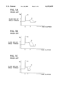
- FIGS. 1A to 1C show the relationship between the sliding resistance of a rotary thread, in which FIG. 1A shows that obtained when a rotary thread of 4 mm stroke per revolution is used; FIG. 1B shows that obtained when a rotary thread of 3 mm stroke per revolution is used; and FIG. 1C shows that obtained when a rotary thread of 2 mm stroke per revolution is used.
- E denotes a point when the rotary driven tool is brought into pressure contact with the work;
- F denotes the bottom dead center of the press;
- G denotes an impact force; and H denotes a rotary resistance, respectively.
- E denotes a point when the rotary driven tool is brought into pressure contact with the work
- F denotes the bottom dead center of the press
- G denotes an impact force;
- H denotes a rotary resistance, respectively.
- this return spring is of gaseous spring type such that a piston member is slidably fitted into a cylinder boredirectly formed in the main body by cutting processing and further a gaseous spring chamber is filed with a compressive fluid (e.g., nitrogen gas) supplied from a separate gas tank.
- a compressive fluid e.g., nitrogen gas
- the rotary driving device occupies two die mounting stations in total in the case of a die mounting station of "1 (1/4)" size, for instance.
- the prior art rotary driving device can be used only with the turret punch press provided with a multi-track (e.g., 3 tracks) die mounting station, thus causing a limitation in use of the rotary driving device with the press machine.
- the other object of the present invention is to provide a rotary driving device for a press machine, which can retain the gas pressure in the gaseous spring chamber for many hours without maintenance, which dose not occupy a plurality of additional die mounting stations, and which dose not limit the press machine to be used therewith.
- the first aspect of the present invention provides a rotary driving device for a press machine, comprising: a main body composed of an upper member and a lower member; a push head member provided for the upper member of said main body reciprocatingly movably in an axial direction thereof and driven in the axial direction by a striker of the press machine; urging means mounted inside the upper member of said main body, for generating a return elastic force to urge said push head member in a direction opposite to a strike direction of the striker; a male thread axle member in mesh with female threads formed in the upper member of said main body and rotatable when moved in an axial direction thereof by said push head member; a lead nut exchangeably and fixedly mounted on the lower member of said main body; a lead thread member in mesh with said lead nut and rotatably supported by said main body, for holding a rotary driven tool; coupling means for coupling said male thread axle member and said lead thread member in torque transmission relationship and in relative axial displacement relationship with respect
- the impact absorbing means is a disk spring and the urging means (41) is at least one airtight gaseous spring unit (15).
- the rotary driving device since the impact force generated the instant that the rotary driving device is brought into pressure contact with the work can be reduced by the shock absorbing member, it is possible to reduce pressure traces formed in the work.
- the second aspect of the present invention provides a rotary driving device for a press machine, comprising: a main body; a push head member provided for said main body reciprocatingly movably in an axial direction thereof and driven in the axial direction by a striker of the press machine; an air-tight gaseous spring unit mounted inside said main body, for generating a return elastic force to urge said push head member in a direction opposite to a strike direction of the striker; a male thread axle member in mesh with female threads formed in said main body and rotatable when moved in an axial direction thereof by said push head member; a lead nut exchangeably and fixedly mounted on said main body; a lead thread member in mesh with said lead nut and rotatably supported by said main body, for holding a rotary driven tool; and coupling means for coupling said male thread axle member and said lead thread member in torque transmission relationship and relative axial displacement relationship with respect to each other so as to absorb a difference in axial speed between said male thread axle member and said
- the male thread axle member is moved in the axial direction thereof against the return elastic force of the gaseous spring unit.
- the male thread member is rotated.
- the rotational force is transmitted to the lead thread member via the coupling means for coupling the male thread axle member and the lead thread member so as to absorb a difference in axial speed between the two members, so that the rotary driving device tool is driven axially and further rotated in accordance a thread pitch of the lead thread member.
- the air-tight gaseous spring units are provided inside the main body so as to generate a return elastic force, respectively to urge the push head member in a direction opposite to the strike direction of the striker, it is possible to prevent the gas leakage from the gaseous spring chamber.
- FIGS. 1A to 1C are graphical representations showing the relationship between the time elapsed and the sliding resistance of male thread members used for the prior art rotary driving device for a press machine;
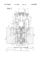
- FIG. 2 is a cross-sectional view showing an embodiment of the rotary driving device for a press machine according to the present invention
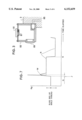
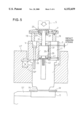
- FIG. 3 is a cross-sectional view showing a cutting lubricant tank disposed on an upper member of the rotary driving device for a press machine according to the present invention shown in FIG. 2;
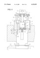
- FIG. 4 is a cross-sectional view showing the state where a press tool is being lowered in the rotary driving device for a press machine shown in FIG. 2;
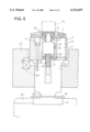
- FIG. 5 is a cross-sectional view showing the state where an impact force is being absorbed in the rotary driving device for a press machine shown in FIG. 2;
- FIG. 6 is a cross-sectional view showing the state where a press tool reaches a bottom dead center in the rotary driving device for a press machine shown in FIG. 2;
- FIG. 7 is a graphical representations showing the relationship between the time elapsed and the sliding resistance of male thread members used for the rotary driving device for a press machine according to the present invention.
- FIG. 2 shows the state where the rotary driving device for a press machine according to the present invention is positioned to the top dead center of the press machine.
- the rotary driving device 1 for a press machine has a cylindrical main body 11, which is composed of a lower member 5, an upper member 3 fixed to the lower member 5 with a plurality of bolts V, and a lead nut support main body 9 removably fitted to a mount hole 7 of the lower member 5.
- the cylindrical main body 11 is inserted into a die mounting hole B formed in an upper turret disk UT of a turret punch press, in such a way as to be floated slightly upward by a plurality of compressive springs SP.
- the die mounting hole B (into which the cylindrical main body 11 is fitted) is "2" in the die mounting station size, for instance.
- a plurality of gaseous spring unit mounting holes 13 are formed around the central axis of the upper member 3 at regular angular intervals. Further, an outer casing 17 of an air-tight gaseous spring unit 15 (urging means) is fitted to each of these gaseous spring unit mounting holes 13.
- This air-tight gaseous spring unit 15 has a piston rod 19 extending upward and fixed to a push head member 21 with a bolt V (the uppermost volt) at the upper end thereof, and serves as a return spring for urging the striker S (striking means) for striking the push head member 21 in the direction opposite to the strike direction of the striker S.
- the push head member 21 is formed with an upper surface 23 facing the striker S (striking means) of the press machine, and movable reciprocatingly in the axial direction of the cylindrical main body 11 (i.e., up and down in FIG. 2) by the piston rods 19.
- a male thread axle member 29 (e.g., ball thread axle or roller thread axle) is supported via a thrust bearing 25 and a radial bearing 27 so as to be rotatable around its central axis thereof.
- the male thread axle member 29 is formed with male threads 31 in mesh with female threads formed in a female thread member 33 mounted on the upper member 3.
- the lead of both the male thread member 31 and the female thread member 33 is determined to be relatively large so as to be rotated smoothly in the axial direction thereof when moved vertically.
- the female thread member 33 is formed with a key 35 in the outer circumferential surface thereof. This key 35 is engaged with a key groove 37 formed in the inner circumferential surface of the upper member 3. Further, a metallic spacer 39 and an impact absorbing member 41 (e.g., a disk spring, an urethane spring, etc.) are interposed between the lower surface of the female thread member 33 and the upper surface of the lower member 5. As this impact absorbing member 41, the disk spring is most preferable from the standpoint of shock reduction.
- an impact absorbing member 41 e.g., a disk spring, an urethane spring, etc.
- the male thread member 29 extends through the female thread member 33 axially in the vertical direction thereof.
- the male thread member 29 is formed with a spline axle portion 43 at the lower end portion thereof located within the lower member 5.
- a lead nut 47 is fixed to a lead nut support main body 9 with a set screw 45.
- This lead nut 47 is formed with a thread hole 49 along the same axial line as that of the male thread member 29 so as to be in mesh with a male thread portion 53 of a lead thread member 51.
- the lead of the thread hole 49 of the lead nut 47 and the male thread portion 53 of the lead thread member 51 is determined to be the same value as the lead of a tap T (described later).
- This lead thread member 51 extends through the lead nut 47 in the vertical direction.
- a spline member 55 is fixed to the upper end portion of this lead thread member 51.
- the spline member 55 is formed with a spline hole 57, into which the spline axle portion 43 of the male thread axle member 29 is spline-coupled movably in the axial direction thereof.
- the lead thread member 51 is supported by the lead nut support main body 9 via a bush 59 so as to be rotatable and further slidably movable in the axial direction thereof.
- a support axle 67 of a tool chuck 65 is fitted into a hollow axle portion 61 of the lead thread member 51 and further fixed thereto with a pin 63 so as to be movable by a predetermined distance in the axial direction thereof.
- a compressive coil spring 69 is provided within the hollow axle portion 61 and between a stopper pin 71 mounted to the lead thread member 51 and the support axle 67 of the tool chuck 65 in order to urge the tool chuck 65 in the downward direction.
- a tap T can be held by the tool chuck 65 so as to be exchanged.
- a chuck protection ring member 73 and a plate push cap 75 are attached with a plurality of bolts 77.
- This chuck protection ring member 73 is fixed to the lower end portion of the lead nut support main body 9 with the bolts 77.
- the plate push cap 75 is urged by another compressive spring 79 in the downward direction. Therefore, this plate push cap 75 is movable relative to the chuck protection ring member 73 by a predetermined axial distance against an elastic force of the compressive coil spring 79.
- the plate push cap 75 is used as a piston actuator of a cutting lubricant supplying pump (not shown) mounted on the cylindrical main body 11.
- a cutting lubricant supplying pump (not shown) mounted on the cylindrical main body 11.
- a lower turret ST is provided under the upper turret UT.
- a die D is mounted and work W to be tapped is mounted on this die D.
- FIG. 3 shows the cutting lubricant tank 83, which is fixedly mounted on the side portion (in a common unoccupied space of the press machine) of the upper member 3, in such a way as not to be obstructive when another die is mounted on the upper turret disk UT.
- the cutting lubricant tank 83 is provided with a cutting lubricant inlet port 87 and a level gauge 89.
- the cutting lubricant inlet port 87 is closed by a cap 91.
- the cutting lubricant is supplied to the tap T through the cutting lubricant passage 85.
- FIG. 2 shows the initial stage where the striker S is located at the uppermost position.
- the striker S is brought into pressure contact with the upper surface 23 of the push head member 21 to push the push head member 21 in the axially downward direction thereof.
- the entire cylindrical main body 11 is lowered toward the upper turret disk UT against the elastic force of the compressive coil springs SP. Therefore, as shown in FIG. 4, the plate push cap 75 is brought into pressure contact with the upper surface of the work W mounted on the lower turret disk ST to push the work W.
- the compressive coil springs 79 are then deformed, so that the cylindrical main body 11 is further lowered relative to the plate push cap 75. Accordingly, the chuck protection ring member 73 is brought into pressure contact with the plate push cap 75 for pumping action, so that the cutting lubricant within the cutting lubricant tank 83 is Jetted toward the tap T.
- the push head member 21 When the push head member 21 is further lowered, the push ead member 21 is further lowered relative to the cylindrical ain body 11 against the elastic force of the gaseous spring units 15.
- the male thread axle member 29 In accompany with the downward motion of the push head member 21, the male thread axle member 29 is moved downward in the axial direction thereof. Consequently, the male thread axle member 29 is lowered being rotated, as shown in FIG. 5, at a rate determined by the thread lead due to mesh between the male thread axle member 29 and the female thread member 33.
- the thread lead is about 3 mm, for instance. In this case, the male thread axle member 29 is lowered by an axial stroke of 3 mm per revolution thereof.
- the thread lead is about 3 mm, it is possible to increase the feed clear distance (material feeding space) between the plate push cap 75 and the die D mounted on the lower turret disk ST twice or more larger than that of the case where the thread lead is about 4 mm, that is, from about 5 mm to about 11 mm, for instance.
- the lead thread member 51 rotates.
- the lead thread member 51 is in mesh with the lead nut 47, the lead thread member 51 is moved downward in the axial direction being rotated at a rate determined by the thread lead, so that the tap T attached to the tool chuck 65 is lowered being rotated to form a female thread in the work W.
- the male thread axle member 29 is lowered in the axial direction at a rate determined by the thread lead of the male thread member 31.
- the lead thread member 51 is lowered at a rate determined by the thread lead of the lead male thread portion 53, that is, at a rate determined by the thread lead the same as that of the tap T.
- the male thread axle member 29 is rotated at a speed the same as that of the lead thread member 51 in the same rotative direction but lowered at a speed higher than that of the lead thread member 51 in the axial direction, so that there exists a difference in the axial stroke between the male thread axle member 29 and the lead thread member 51.
- both the members 29 and 51 are rotated being slid relative to each other at the spline coupled portion in the axial direction thereof, with the result that it is possible to rotate and further move both the members 29 and 51 in the axial direction relative to each other without any trouble.
- the spline axle portion 43 and the spline member 55 can couple both the male thread axle member 29 and the lead thread member 51 in torque transmission relationship and further in relative axial displacement relationship with respect to each other in such a way that a difference in axial speed between both the members 29 and 51 can be absorbed.
- FIG. 7 shows the relationship between the sliding resistance generated when the male thread axle member 29 is rotated and the time elapsed, in which the symbol J denotes a time point when the cylindrical main body 11 is brought into pressure contact with the work W; K denotes the bottom dead center of the press machine; M denotes the impact value; N denotes the rotative resistance; and Q denotes the stroke of the impact absorbing member.
- the impact absorbing member 41 is interposed between the lower surface of the female thread member 33 and the upper surface of the lower member 5, it is possible to reduce the impact resistance owing to the action of the impact absorbing member 41 down to about a half of that generated when no impact absorbing member is interposed as indicated by a dotted line. That is, since the impact force can be reduced, it is possible to reduce the impact or pressure traces formed on the plate material W to be tapped.
- the rotary driving device for a press machine since the impact force generated when the rotary driving device is brought into pressure contact with the work can be reduced, it is possible to prevent the work material from being damaged by the device; that is, to reduce pressure traces formed on the surface of the work.
- the gaseous spring units (urging means) for returning the push head member in the direction opposite to the strike direction of the striker of the press machine are of airtight gaseous spring unit type mounted within the rotary driving device itself, it is possible to provide a rotary driving device for a press machine, which can prevent the gas leakage and thereby retain the gas pressure in the gaseous spring chamber without replenishment and maintenance of the gas, so that it is possible to realize an unmanned operation of the rotary driving device for a long time at night, for instance.
- gaseous spring units are mounted within the main body of the rotary driving device without need of any separate gas tanks, a plurality of die mounting stations are not occupied when the rotary driving device is mounted on the turret disk, so that it is possible to use the rotary driving device for any press machines without any limitation.
Landscapes
- Engineering & Computer Science (AREA)
- Mechanical Engineering (AREA)
- Presses And Accessory Devices Thereof (AREA)
- Press Drives And Press Lines (AREA)
Priority Applications (1)
| Application Number | Priority Date | Filing Date | Title |
|---|---|---|---|
| US08/710,551 US6152659A (en) | 1994-02-02 | 1996-09-19 | Rotary driving device for press machine |
Applications Claiming Priority (4)
| Application Number | Priority Date | Filing Date | Title |
|---|---|---|---|
| JP1084994 | 1994-02-02 | ||
| US26290194A | 1994-06-21 | 1994-06-21 | |
| JP6-10849 | 1994-07-04 | ||
| US08/710,551 US6152659A (en) | 1994-02-02 | 1996-09-19 | Rotary driving device for press machine |
Related Parent Applications (1)
| Application Number | Title | Priority Date | Filing Date |
|---|---|---|---|
| US26290194A Continuation | 1994-02-02 | 1994-06-21 |
Publications (1)
| Publication Number | Publication Date |
|---|---|
| US6152659A true US6152659A (en) | 2000-11-28 |
Family
ID=11761808
Family Applications (1)
| Application Number | Title | Priority Date | Filing Date |
|---|---|---|---|
| US08/710,551 Expired - Lifetime US6152659A (en) | 1994-02-02 | 1996-09-19 | Rotary driving device for press machine |
Country Status (4)
| Country | Link |
|---|---|
| US (1) | US6152659A (de) |
| EP (1) | EP0666134B1 (de) |
| CA (1) | CA2125933C (de) |
| DE (1) | DE69414363T2 (de) |
Cited By (8)
| Publication number | Priority date | Publication date | Assignee | Title |
|---|---|---|---|---|
| US6547496B2 (en) * | 2001-07-27 | 2003-04-15 | Danly Iem, Division Of Connell Limited Partnership | Die tapping unit |
| US20050271485A1 (en) * | 2002-10-28 | 2005-12-08 | Shigeyoshi Kouno | Tapping method and device, and punch press |
| US20060127191A1 (en) * | 2004-12-10 | 2006-06-15 | Chun Victor L | Servo tapping unit with built in shock protection |
| CN102494942A (zh) * | 2011-11-30 | 2012-06-13 | 北京交通大学 | 双电机同步驱动可旋转岩土试验机 |
| CN102519795A (zh) * | 2011-11-30 | 2012-06-27 | 北京交通大学 | 单电机驱动可旋转岩土试验机 |
| US20150165534A1 (en) * | 2013-12-13 | 2015-06-18 | Ridge Tool Company | Thread forming using an impact driver |
| US10940543B2 (en) | 2017-06-22 | 2021-03-09 | Pass Stanztechnik Ag | Drilling tool and method of operating a drilling tool |
| CN114147511A (zh) * | 2021-11-30 | 2022-03-08 | 昆山鑫善水自动化科技有限公司 | 一种自动化设备配件及其加工工艺 |
Families Citing this family (4)
| Publication number | Priority date | Publication date | Assignee | Title |
|---|---|---|---|---|
| US7487709B2 (en) | 2002-11-02 | 2009-02-10 | Suspa Holding Gmbh | Adjustable-length actuating element |
| CN102636393B (zh) * | 2012-05-17 | 2013-11-13 | 北京交通大学 | 三电机同步驱动旋转岩土试验机 |
| US11465220B2 (en) | 2018-09-30 | 2022-10-11 | Wilson Tool International Inc. | Driving system for machining tools or other tooling usable with metal-fabricating presses or other machines |
| CN109443167B (zh) * | 2018-10-10 | 2020-11-03 | 安徽巨一科技股份有限公司 | 一种离合器摩擦片间隙测量方法及测量装置 |
Citations (10)
| Publication number | Priority date | Publication date | Assignee | Title |
|---|---|---|---|---|
| US3767313A (en) * | 1971-10-20 | 1973-10-23 | Zephyr Mfg Co | Positive feed drill |
| DE3322566A1 (de) * | 1983-06-23 | 1985-01-10 | Jakob GmbH & Co KG, 8751 Kleinwallstadt | Gewindespindel-antrieb fuer werkzeug- und werkstueckschlitten |
| EP0212006A1 (de) * | 1985-08-02 | 1987-03-04 | MECLOSTAMPI di A. Canobbio & C. s.a.s. | Gewindebohrvorrichtung an Pressen |
| EP0305762A1 (de) * | 1987-08-17 | 1989-03-08 | Siemens Aktiengesellschaft | Elektromotorischer Stellantrieb mit zeitabhängiger Endlagen- Abschaltung zum Einsatz in Steuer- oder Regeleinrichtungen für strömende Medien |
| EP0394925A2 (de) * | 1989-04-24 | 1990-10-31 | Robotics Automation Consulting Engineering Industries, Inc. | Gewindebohrgerät für eine Stanzpresse |
| US5012709A (en) * | 1990-08-13 | 1991-05-07 | Su Jen Sung | Impact screw driver |
| JPH0451323A (ja) * | 1990-06-20 | 1992-02-19 | Hitachi Ltd | プログラム構造図表示方式 |
| JPH04115817A (ja) * | 1990-09-07 | 1992-04-16 | Amada Metrecs Co Ltd | プレス機械用タッピング装置 |
| JPH04115816A (ja) * | 1990-09-07 | 1992-04-16 | Amada Metrecs Co Ltd | プレス機械用タッピング装置 |
| WO1993013900A1 (en) * | 1992-01-21 | 1993-07-22 | Maynard Scott D | In-die tapping tool |
-
1994
- 1994-06-01 DE DE69414363T patent/DE69414363T2/de not_active Expired - Lifetime
- 1994-06-01 EP EP94108482A patent/EP0666134B1/de not_active Expired - Lifetime
- 1994-06-15 CA CA002125933A patent/CA2125933C/en not_active Expired - Fee Related
-
1996
- 1996-09-19 US US08/710,551 patent/US6152659A/en not_active Expired - Lifetime
Patent Citations (10)
| Publication number | Priority date | Publication date | Assignee | Title |
|---|---|---|---|---|
| US3767313A (en) * | 1971-10-20 | 1973-10-23 | Zephyr Mfg Co | Positive feed drill |
| DE3322566A1 (de) * | 1983-06-23 | 1985-01-10 | Jakob GmbH & Co KG, 8751 Kleinwallstadt | Gewindespindel-antrieb fuer werkzeug- und werkstueckschlitten |
| EP0212006A1 (de) * | 1985-08-02 | 1987-03-04 | MECLOSTAMPI di A. Canobbio & C. s.a.s. | Gewindebohrvorrichtung an Pressen |
| EP0305762A1 (de) * | 1987-08-17 | 1989-03-08 | Siemens Aktiengesellschaft | Elektromotorischer Stellantrieb mit zeitabhängiger Endlagen- Abschaltung zum Einsatz in Steuer- oder Regeleinrichtungen für strömende Medien |
| EP0394925A2 (de) * | 1989-04-24 | 1990-10-31 | Robotics Automation Consulting Engineering Industries, Inc. | Gewindebohrgerät für eine Stanzpresse |
| JPH0451323A (ja) * | 1990-06-20 | 1992-02-19 | Hitachi Ltd | プログラム構造図表示方式 |
| US5012709A (en) * | 1990-08-13 | 1991-05-07 | Su Jen Sung | Impact screw driver |
| JPH04115817A (ja) * | 1990-09-07 | 1992-04-16 | Amada Metrecs Co Ltd | プレス機械用タッピング装置 |
| JPH04115816A (ja) * | 1990-09-07 | 1992-04-16 | Amada Metrecs Co Ltd | プレス機械用タッピング装置 |
| WO1993013900A1 (en) * | 1992-01-21 | 1993-07-22 | Maynard Scott D | In-die tapping tool |
Non-Patent Citations (2)
| Title |
|---|
| European Search Report EP 94 10 8482 15 Search Completed May 1995. * |
| European Search Report--EP 94 10 8482 15--Search Completed May 1995. |
Cited By (14)
| Publication number | Priority date | Publication date | Assignee | Title |
|---|---|---|---|---|
| US6547496B2 (en) * | 2001-07-27 | 2003-04-15 | Danly Iem, Division Of Connell Limited Partnership | Die tapping unit |
| US7559727B2 (en) * | 2002-10-28 | 2009-07-14 | Amada Company Limited | Tapping method and device, and punch press |
| US20050271485A1 (en) * | 2002-10-28 | 2005-12-08 | Shigeyoshi Kouno | Tapping method and device, and punch press |
| US7597512B2 (en) | 2002-10-28 | 2009-10-06 | Amada Company, Limited | Tapping method, tapping device and punch press |
| US20080044245A1 (en) * | 2002-10-28 | 2008-02-21 | Amada Company, Limited | Tapping method, tapping device and punch press |
| US7326008B2 (en) | 2004-12-10 | 2008-02-05 | Danly Iem, Llc | Servo tapping unit with built in shock protection |
| US20060127191A1 (en) * | 2004-12-10 | 2006-06-15 | Chun Victor L | Servo tapping unit with built in shock protection |
| CN102494942A (zh) * | 2011-11-30 | 2012-06-13 | 北京交通大学 | 双电机同步驱动可旋转岩土试验机 |
| CN102519795A (zh) * | 2011-11-30 | 2012-06-27 | 北京交通大学 | 单电机驱动可旋转岩土试验机 |
| CN102519795B (zh) * | 2011-11-30 | 2013-12-18 | 北京交通大学 | 单电机驱动可旋转岩土试验机 |
| CN102494942B (zh) * | 2011-11-30 | 2013-12-18 | 北京交通大学 | 双电机同步驱动可旋转岩土试验机 |
| US20150165534A1 (en) * | 2013-12-13 | 2015-06-18 | Ridge Tool Company | Thread forming using an impact driver |
| US10940543B2 (en) | 2017-06-22 | 2021-03-09 | Pass Stanztechnik Ag | Drilling tool and method of operating a drilling tool |
| CN114147511A (zh) * | 2021-11-30 | 2022-03-08 | 昆山鑫善水自动化科技有限公司 | 一种自动化设备配件及其加工工艺 |
Also Published As
| Publication number | Publication date |
|---|---|
| DE69414363D1 (de) | 1998-12-10 |
| EP0666134B1 (de) | 1998-11-04 |
| EP0666134A1 (de) | 1995-08-09 |
| DE69414363T2 (de) | 1999-04-01 |
| CA2125933C (en) | 2004-11-23 |
| CA2125933A1 (en) | 1995-08-03 |
Similar Documents
| Publication | Publication Date | Title |
|---|---|---|
| US6152659A (en) | Rotary driving device for press machine | |
| JP2986174B2 (ja) | パンチプレス用タッピング装置 | |
| US5927700A (en) | Transmission device for a clamp | |
| US4172683A (en) | Machine tool having drawbar mechanism | |
| US20040112649A1 (en) | Rock drill | |
| JPH0390227A (ja) | パンチプレス用マーキングツールホルダ | |
| US7070491B2 (en) | Machine tool with fluid actuated helical adjustment of abrasive elements | |
| US5348429A (en) | Tapping apparatus with rapid tap advance/retraction | |
| US2437191A (en) | Upsetting tool for hollow rivets | |
| US4386516A (en) | Automatic bending machine | |
| JP2001182715A (ja) | 自動カラー形成ドリル装置 | |
| US3704957A (en) | Cam operated drill unit | |
| US7694616B2 (en) | Spindle drive support | |
| US5752789A (en) | Right angle peck drill | |
| EP1279456A1 (de) | Gewindeschneideinheit für Presse | |
| NO764280L (de) | ||
| US3322208A (en) | Impact tool | |
| JPH0871848A (ja) | 直線運動を回転運動に変換する装置および同装置を用いたプレス機械用回転工具装置 | |
| US3687070A (en) | Press assembly | |
| JP2527541Y2 (ja) | プレス機械用タッピング装置 | |
| CN112139531B (zh) | 一种用于金属块的打孔装置 | |
| US11583987B2 (en) | Impact hammer system | |
| CN113732118A (zh) | 一种翻板式数控折弯机 | |
| CN112122655A (zh) | 一种刹车片自动钻孔机 | |
| US10710229B2 (en) | Impact hammer |
Legal Events
| Date | Code | Title | Description |
|---|---|---|---|
| FEPP | Fee payment procedure |
Free format text: PAYOR NUMBER ASSIGNED (ORIGINAL EVENT CODE: ASPN); ENTITY STATUS OF PATENT OWNER: LARGE ENTITY |
|
| STCF | Information on status: patent grant |
Free format text: PATENTED CASE |
|
| FPAY | Fee payment |
Year of fee payment: 4 |
|
| FPAY | Fee payment |
Year of fee payment: 8 |
|
| FPAY | Fee payment |
Year of fee payment: 12 |