US613331A - Clothes-drier - Google Patents
Clothes-drier Download PDFInfo
- Publication number
- US613331A US613331A US613331DA US613331A US 613331 A US613331 A US 613331A US 613331D A US613331D A US 613331DA US 613331 A US613331 A US 613331A
- Authority
- US
- United States
- Prior art keywords
- arms
- hanger
- bracket
- bars
- bar
- Prior art date
- Legal status (The legal status is an assumption and is not a legal conclusion. Google has not performed a legal analysis and makes no representation as to the accuracy of the status listed.)
- Expired - Lifetime
Links
Images


Classifications
-
- A—HUMAN NECESSITIES
- A47—FURNITURE; DOMESTIC ARTICLES OR APPLIANCES; COFFEE MILLS; SPICE MILLS; SUCTION CLEANERS IN GENERAL
- A47G—HOUSEHOLD OR TABLE EQUIPMENT
- A47G25/00—Household implements used in connection with wearing apparel; Dress, hat or umbrella holders
- A47G25/02—Dress holders; Dress suspending devices; Clothes-hanger assemblies; Clothing lifters
- A47G25/06—Clothes hooks; Clothes racks; Garment-supporting stands with swingable or extending arms
- A47G25/0685—Collapsible clothes racks, e.g. swingable, foldable, extendible
Definitions
- My invention relates to certain improvements in clothes-driers, particularly that class employing a series of radial hanger arms or bars upon which the clothes or articles are suspended or exposed for drying.
- the invention consists, primarily, of a loop or socket adapted to permit the sliding therein of a hanger bar or arm and to freely turn or pivot on the bracket with which it cooperates, and of the construction and combination of parts, all substantially as hereinafter more fully disclosed, and specifically pointed out in the claims.
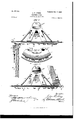
- Figure 1 is a plan view thereof with the hanger bars or arms placed for use.
- Fig. 2 is a View of the same with said arms or bars in a pendent position.
- Fig. 3 is a similar View, except the hanger bars or arms are placed upstanding, the other position they may be caused to assume when out of use.
- Fig. 4 is a plan view of the invention.
- Fig. 5 is a side view of the same.
- Fig. 6 is an inverted plan view thereof.
- Fig. 7 is a de- Serial No. 680,180- (No model.)
- the semiconical portion a has a plane or flat upper back portion a with recesses or notches a a in its bottom and top edges, respectively, to receive screws or fastenings to secure the bracket at a suitable point upon the wall.
- the raised portion a of the base of the bracket A has a series or row of radial apertures oropenings b close to its outer edge or curvature, as shown, the purpose of which will appear later on.
- B B are the clothes-hanger arms or bars, the number of which is predetermined by the number of openings or apertures 19 produced in the bracket A, and O O are loops or sockets adapted to receive each a hanger bar or arm B and permit the sameto slide therein, as presently seen.
- loops or sockets may be otherwise suitably shaped, according to the contour in cross-section of the hanger bars or arms to be accommodated, and are each provided at one end, (its inner end,) outside of its hanger-bar-receiving chamber, with an upwardly curved or hooked projection or stud 0, so adapted that the relative angularity of its position with said loop or socket is such that while by presenting it at a certain angle to a line passing through an opening b in the base B it can be inserted or engaged with said opening with which it is designed to be interlocked, yet after such insertion or engagement it will not become accidentally disengaged therefrom when the loop or socket, with a hanger arm or bar, depends simply by gravity or is moved or swung outward from under the base B, as in positioning each bar or arm for use.
- the loops or sockets in addition to being adapted to accommodate or conform to the outline of the hanger bar or arm, are also each preferably frame-like in its normal upper portion, with its sides extending downward therefrom and terminating in a single central underneath cross-piece, as shown.
- the loops or sockets C are adapted to allow the hanger bars or arms to extend straight out horizontally by means of the raised portion a of the base at, additional space being thus provided equal to the thickness of the upper walls of the loops or sockets, while the inner upper surfaces of the bars or arms rest directly in contact with the depressed or inner portion a of the base and are guarded by shallow rib-like radial projections (1 upon the under side of said depressed portion against lateral displacement.
- the hanger bars or arms B are limited in their endwise movement by slight projections or stops 6, arranged upon their under sides and adapted to engage the ends of their loops or sockets O C as said bars or arms are moved inward or outward in positioning them for use or folding them.
- the bracket A being suitably disposed and secured in position upon the wall, the arms or bars B are raised or brought to a horizontal position, the loops or sockets O carrying them, pivoting or turning, by means of their hooked studs or projections 0, upon said bracket. Said arms or bars are then slid or moved inward to cause their inner ends to rest in contact with the under side of the depressed portion a of said bracket, and thus effect their firm retention in position for use, said inward movement of said bars or arms being limited by the engagement of the outer stops 6 of said bars or arms with the opposite edges of said loops or sockets.
- my invention as above disclosed is possessed of great simplicity, therefore capable of manufacture at the minimum cost, and is adapted to effect the ready placing of the hanger-arms in position when required for use and to permit the folding of the same with facility and their disposition out of the way when dequired for use. Itisalsoadaptedtobecompactlypacked for shipment or conveniently stored and readily exposed or displayed when offered for sale or put on the market.
- the combination of the bracket having an outer raised portion provided with a series of radial apertures or openings and an inner depressed portion, a hanger bar or arm, and a loop or socket for said arm or bar, having an upwardly-curved end loop outside of its hanger-bar-receiving chamber, said hanger-bar adapted to slide in said loop or socket and bear upon the under side of said bracket, substantially as set forth.
- the bracket having an outer raised portion provided with a series of radial openings or apertures, and an inner depressed portion having a series of radial rib-like projections upon its under side, a hanger bar or arm having stops upon its under side, a loop or socket for said hanger bar or arm, having an end curved or hooked projection, or stud, and adapted to permit the sliding therein of said hanger bar or arm, said hooked or curved stud or projection being adapted to engage said openings or apertures and to turn or pivot on said bracket, substantially as set forth.
Landscapes
- Holders For Apparel And Elements Relating To Apparel (AREA)
Description
No. 6l3,33l. Patented Nov. I, I898.
J. B. STORY.
CLOTHES DRIER.
(Application filed May 9, 1898.) No Model.) -3 Sheets-Sheet I.
wmmw v flttozmq No. 6l3,33l. Patented Nov. I, I898. J. B. STORY. CLOTHES DRIER.
(Appl ahon filed May 9, 1898.)
we Model.) 3 sheets-sheet 2. J? .2.
"li"' W 1| ini Him 0 Patented Nov. I, I898,
L J. B. STORY.
CLOTHES DRIER. (Application filed. ay 9, 189
3 Sheets-Sheet 3.
(No Model.)
q j y NITED STATES PATENT Frrc,
JUDGE B. STORY, OF BLOOMINGTON, ILLINOIS.
CLOTHES-DRIER.
SPECIFICATION forming part of Letters Patent No. 613,331, dated November 1, 1898.
Application filed May 9, 1898.
To all whom it nuty concern:
Be it known that I, JUDGE B. STORY, a citizen of the United States, residing at Blooming ton, in the county of McLean and State of Illinois, have invented certain new and useful Improvements in Ctlothes-Driers; and I do hereby declare the following to be a full, clear, and exact description of the invention, such as will" enable others skilled in the art to which it appertains to make and use the same.
My invention relates to certain improvements in clothes-driers, particularly that class employing a series of radial hanger arms or bars upon which the clothes or articles are suspended or exposed for drying.
It has for its objects, among other things, to greatly simplify construction, consequently lessen cost of manufacture, and to effect the ready placing of the hanger arms or bars in position and their withdrawal from use and disposition out of the way when thus withdrawn; also, to provide for the compact folds ing and packing the same for shipment, for convenience in storing, and for exposure or display when offered for sale or put on the market.
To these ends the invention consists, primarily, of a loop or socket adapted to permit the sliding therein of a hanger bar or arm and to freely turn or pivot on the bracket with which it cooperates, and of the construction and combination of parts, all substantially as hereinafter more fully disclosed, and specifically pointed out in the claims.
It will be understood that latitude is allowed herein as to details, as they may be varied without departing from the spirit or principles of my invention, and the same yet remain intact.
In the accompanying drawings, illustrating the preferred form of carrying out my invention, Figure 1 is a plan view thereof with the hanger bars or arms placed for use. Fig. 2 is a View of the same with said arms or bars in a pendent position. Fig. 3 is a similar View, except the hanger bars or arms are placed upstanding, the other position they may be caused to assume when out of use. Fig. 4 is a plan view of the invention. Fig. 5 is a side view of the same. Fig. 6 is an inverted plan view thereof. Fig. 7 is a de- Serial No. 680,180- (No model.)
with its divergent or flared lower end joining said inner depressed portion. The semiconical portion a has a plane or flat upper back portion a with recesses or notches a a in its bottom and top edges, respectively, to receive screws or fastenings to secure the bracket at a suitable point upon the wall.
The raised portion a of the base of the bracket A has a series or row of radial apertures oropenings b close to its outer edge or curvature, as shown, the purpose of which will appear later on.
B B are the clothes-hanger arms or bars, the number of which is predetermined by the number of openings or apertures 19 produced in the bracket A, and O O are loops or sockets adapted to receive each a hanger bar or arm B and permit the sameto slide therein, as presently seen. These loops or sockets, though shown as rectangular in general outline, may be otherwise suitably shaped, according to the contour in cross-section of the hanger bars or arms to be accommodated, and are each provided at one end, (its inner end,) outside of its hanger-bar-receiving chamber, with an upwardly curved or hooked projection or stud 0, so adapted that the relative angularity of its position with said loop or socket is such that while by presenting it at a certain angle to a line passing through an opening b in the base B it can be inserted or engaged with said opening with which it is designed to be interlocked, yet after such insertion or engagement it will not become accidentally disengaged therefrom when the loop or socket, with a hanger arm or bar, depends simply by gravity or is moved or swung outward from under the base B, as in positioning each bar or arm for use.
The loops or sockets, in addition to being adapted to accommodate or conform to the outline of the hanger bar or arm, are also each preferably frame-like in its normal upper portion, with its sides extending downward therefrom and terminating in a single central underneath cross-piece, as shown.
The loops or sockets C, it will be seen, are adapted to allow the hanger bars or arms to extend straight out horizontally by means of the raised portion a of the base at, additional space being thus provided equal to the thickness of the upper walls of the loops or sockets, while the inner upper surfaces of the bars or arms rest directly in contact with the depressed or inner portion a of the base and are guarded by shallow rib-like radial projections (1 upon the under side of said depressed portion against lateral displacement.
The hanger bars or arms B are limited in their endwise movement by slight projections or stops 6, arranged upon their under sides and adapted to engage the ends of their loops or sockets O C as said bars or arms are moved inward or outward in positioning them for use or folding them.
In operation the bracket A being suitably disposed and secured in position upon the wall, the arms or bars B are raised or brought to a horizontal position, the loops or sockets O carrying them, pivoting or turning, by means of their hooked studs or projections 0, upon said bracket. Said arms or bars are then slid or moved inward to cause their inner ends to rest in contact with the under side of the depressed portion a of said bracket, and thus effect their firm retention in position for use, said inward movement of said bars or arms being limited by the engagement of the outer stops 6 of said bars or arms with the opposite edges of said loops or sockets.
In order to fold the arms or barsB after use, it is only required to slide or move the same outward, which movement will be limited by the inner stops 6 on said bars or arms engaging the opposite edges of the loops or sockets 0, when the inner ends of said bars or arms will be removed from the depressed portion a of the bracket A, permitting said bars or arms to depend from said bracket out of the way. If, however, it should be desired to stand the bars or arms B upon the bracketA back against the wall, the loops or sockets are so disposed with said arms or bars as to permit the disengagement of said loops or sockets therefrom and then reengaging said loops or sockets with said bracket from the upper side thereof, as disclosedv in Fig. 3, as will be readily appreciated. In this event in case there should not be the requisite space between the bracket A and the ceiling of the room I can provide therefor by lowering the bracket. The modification as disclosed in Fig. Sis designed as one way of carrying out this purpose, wherein is shown a dovetailed tongue-piece f, suitably secured to the wall and fitting a correspondingly grooved back plate f of the bracket A, said back plate being provided with an adjusting or holding screw or screws f adapted to engage or bear upon said tongue-piece f.
It will be seen that my invention as above disclosed is possessed of great simplicity, therefore capable of manufacture at the minimum cost, and is adapted to effect the ready placing of the hanger-arms in position when required for use and to permit the folding of the same with facility and their disposition out of the way when notrequired for use. Itisalsoadaptedtobecompactlypacked for shipment or conveniently stored and readily exposed or displayed when offered for sale or put on the market.
Having thus fully described my invention, what I claim, and desire to secure by Letters Patent, is
1. In a clothes-drier, the combination, with a bracket, of a hanger arm or bar, and a loop or sockettherefor,l1avingoutsideofits hanger= bar=receiving chamber an upwardly-curved end hook adapted to pivot or turn on said bracket, said hanger-bar adapted to slide in said socket or loop and bear upon the under side of said bracket, substantially as set forth.
2. In a clothes-drier, the combination of the bracket having an outer raised portion provided with a series of radial apertures or openings and an inner depressed portion, a hanger bar or arm, and a loop or socket for said arm or bar, having an upwardly-curved end loop outside of its hanger-bar-receiving chamber, said hanger-bar adapted to slide in said loop or socket and bear upon the under side of said bracket, substantially as set forth.
3. In aclothes-drier, the combination of the bracket having an outer raised portion provided with a series of radial openings or apertures, and an inner depressed portion having a series of radial rib-like projections upon its under side, a hanger bar or arm having stops upon its under side, a loop or socket for said hanger bar or arm, having an end curved or hooked projection, or stud, and adapted to permit the sliding therein of said hanger bar or arm, said hooked or curved stud or projection being adapted to engage said openings or apertures and to turn or pivot on said bracket, substantially as set forth.
In testimony whereof I affix my signature in presence of two witnesses.
JUDGE B. STORY.
\Vitnesses:
A. L. VINEY, G. W. SHARP.
ICC
Publications (1)
| Publication Number | Publication Date |
|---|---|
| US613331A true US613331A (en) | 1898-11-01 |
Family
ID=2681942
Family Applications (1)
| Application Number | Title | Priority Date | Filing Date |
|---|---|---|---|
| US613331D Expired - Lifetime US613331A (en) | Clothes-drier |
Country Status (1)
| Country | Link |
|---|---|
| US (1) | US613331A (en) |
-
0
- US US613331D patent/US613331A/en not_active Expired - Lifetime
Similar Documents
| Publication | Publication Date | Title |
|---|---|---|
| US4865283A (en) | Merchandising display stand | |
| US3302917A (en) | Hanger member | |
| US1732162A (en) | Clothes rack | |
| US663046A (en) | Goods-exhibitor. | |
| US955734A (en) | Display-rack. | |
| US1856239A (en) | Clothes assembling rack | |
| US426697A (en) | Clothes-drier | |
| US2246692A (en) | Bag rack | |
| US613331A (en) | Clothes-drier | |
| US890023A (en) | Automatic folding clothes-hanger. | |
| US242120A (en) | Geoege eastman | |
| US4396124A (en) | Hanger bar | |
| US665877A (en) | Garment-rack. | |
| US1236212A (en) | Folding clothes-rack. | |
| US411387A (en) | Half to charles l | |
| US332198A (en) | Dwight gbidley | |
| US664063A (en) | Garment-hanger. | |
| US420838A (en) | Clothes-drier | |
| US3265216A (en) | Display stand for hang-up cards | |
| US1236158A (en) | Display-rack. | |
| US891029A (en) | Display apparatus. | |
| US609743A (en) | Garment-hanger | |
| US1228636A (en) | Garment-hanger. | |
| US475243A (en) | langdoxl | |
| US329018A (en) | Finger-ring tray |