US6131894A - Liquid sealed type rubber mount device - Google Patents
Liquid sealed type rubber mount device Download PDFInfo
- Publication number
- US6131894A US6131894A US09/131,839 US13183998A US6131894A US 6131894 A US6131894 A US 6131894A US 13183998 A US13183998 A US 13183998A US 6131894 A US6131894 A US 6131894A
- Authority
- US
- United States
- Prior art keywords
- cup
- high frequency
- medium
- liquid chamber
- type rubber
- Prior art date
- Legal status (The legal status is an assumption and is not a legal conclusion. Google has not performed a legal analysis and makes no representation as to the accuracy of the status listed.)
- Expired - Lifetime
Links
Images


Classifications
-
- F—MECHANICAL ENGINEERING; LIGHTING; HEATING; WEAPONS; BLASTING
- F16—ENGINEERING ELEMENTS AND UNITS; GENERAL MEASURES FOR PRODUCING AND MAINTAINING EFFECTIVE FUNCTIONING OF MACHINES OR INSTALLATIONS; THERMAL INSULATION IN GENERAL
- F16F—SPRINGS; SHOCK-ABSORBERS; MEANS FOR DAMPING VIBRATION
- F16F13/00—Units comprising springs of the non-fluid type as well as vibration-dampers, shock-absorbers, or fluid springs
- F16F13/04—Units comprising springs of the non-fluid type as well as vibration-dampers, shock-absorbers, or fluid springs comprising both a plastics spring and a damper, e.g. a friction damper
- F16F13/06—Units comprising springs of the non-fluid type as well as vibration-dampers, shock-absorbers, or fluid springs comprising both a plastics spring and a damper, e.g. a friction damper the damper being a fluid damper, e.g. the plastics spring not forming a part of the wall of the fluid chamber of the damper
- F16F13/08—Units comprising springs of the non-fluid type as well as vibration-dampers, shock-absorbers, or fluid springs comprising both a plastics spring and a damper, e.g. a friction damper the damper being a fluid damper, e.g. the plastics spring not forming a part of the wall of the fluid chamber of the damper the plastics spring forming at least a part of the wall of the fluid chamber of the damper
- F16F13/10—Units comprising springs of the non-fluid type as well as vibration-dampers, shock-absorbers, or fluid springs comprising both a plastics spring and a damper, e.g. a friction damper the damper being a fluid damper, e.g. the plastics spring not forming a part of the wall of the fluid chamber of the damper the plastics spring forming at least a part of the wall of the fluid chamber of the damper the wall being at least in part formed by a flexible membrane or the like
- F16F13/108—Units comprising springs of the non-fluid type as well as vibration-dampers, shock-absorbers, or fluid springs comprising both a plastics spring and a damper, e.g. a friction damper the damper being a fluid damper, e.g. the plastics spring not forming a part of the wall of the fluid chamber of the damper the plastics spring forming at least a part of the wall of the fluid chamber of the damper the wall being at least in part formed by a flexible membrane or the like characterised by features of plastics springs, e.g. attachment arrangements
Definitions
- This invention relates to a liquid sealed type rubber mount device such as an engine mount rubber for an automobile vehicle.
- Such a liquid sealed type rubber mount device is disclosed for example in Japanese Patent Publication (Kokoku) No. Sho62-23178, in which a first support member is attached to a vibration source, a cylindrical shaped second support member is attached to a vehicle body, a conical shaped rubber body is interposed between the two support members, and a liquid chamber is formed within tie rubber body to admit buffering liquid therein, wherein a thin wall portion is partially provided on the rubber body, a disk shaped member is provided projecting from the first support member into the second support member, a partition member is arranged to divide the second support member into two chambers, while an annular passage is formed between an outer peripheral portion thereof and an inner wall of the second support member and a diaphragm is provided on a bottom portion of the second support member.
- the device since it is aimed to damp a vibration by a flow resistance, the device can deal with the vibration of some 10 Hz and to the contrary, it has a high dynamic spring characteristic in a frequency range for example 100 to 500 Hz and a high frequency range for example 500 to 1000 Hz.
- the rubber wall of the liquid chamber is not provided with such a thin portion and is instead formed with a uniform thickness with respect to to a circumferential direction, and a disk shaped member, which is connected to a vibration input side projecting into the liquid chamber, whereby the low dynamic spring characteristic is realized.
- a curve shown as a conventional example in FIG. 3 describes a change of the dynamic spring characteristics vs. the frequency in such a construction.
- the disk shaped member acts as a medium frequency device and a minimum value a is generated by a liquid column resonance at a specified frequency in the medium frequency range accompanying a flow of liquid in a gap between the peripheral rubber wall and the disk shaped member.
- a liquid sealed type rubber mount device comprising a first support member attached to a vibration source, a second support member attached to a vehicle body, an elastic member formed in a substantially conical shape interposed between the first and second support members, the first and second support members being adapted to form a liquid chamber therebetween with at least a part of a wall thereof, a partition wall dividing the liquid chamber into a main chamber and an auxiliary chamber, and an orifice passage formed within the partition wall for usually communicating the two liquid chambers, wherein a part of the wall composing said auxiliary liquid chamber is formed of a diaphragm, a medium to high frequency device is provided, which is attached to the first support member projecting into the main liquid chamber so as to absorb a vibration component in the medium to high frequency by forming a flow space between the inner wall of the conical portion of the elastic member and therewith, and a thin wall portion is formed on a part of a conical portion of the
- the membrane resonance means a resonance phenomenon generated when the thin wall portion of the elastic member deforms resiliently with spring property by a liquid flow within the liquid chamber.
- the medium frequency range in the present invention means especially 100 to 500 Hz region among the ordinary medium frequency range of 40 to 500 Hz.
- thin wall portion may be provided at plural positions and each thin wall portion can be arranged on a symmetric position in a same shape.
- said thin wall portions may be provided at plural positions and each thin wall portion can also be arranged on symmetrical positions in different shapes.
- the second invention includes a liquid sealed type rubber mount device of the first invention, wherein said medium to high frequency device may be formed in a non-circular shape cut out a portion adjacent to the thin wall portion among the peripheral portion thereof viewed from a principal input direction of the vibration and a gap between the cut out portion and the thin wall portion is made to be larger than that in other portions.
- the third invention includes a liquid sealed rubber mount device of the first invention, wherein said partition wall may be arranged as an elastic partition wall changing the dynamic spring characteristic thereof according to an inner pressure change in the liquid chamber.
- the fourth invention includes a liquid sealed mount rubber device of the first invention, wherein instead of said partition wall, an elasticity control mechanism is provided to arrange a plurality of orifice passages having different properties to switch at the designated frequencies.
- the fifth invention includes a liquid sealed rubber mount device of the first invention, further comprises an open and close portion to switch the orifice passages formed on a part of a diaphragm composing an auxiliary chamber, a driving portion to open and close the open and close portion, wherein a metal-made cylindrical covering member is provided to cover a periphery of the elastic member, on an opening side of an end thereof two kind of claws as a first and a second claw are formed in a different height and a first caulking portion fixing the partition wall and the diaphragm via a caulking with the first claw and a second caulking portion fixing a driving portion via a caulking with the second claw are provided.
- the sixth invention includes a liquid sealed rubber mount device of the fifth invention, the driving portion comprises a top portion abutting against the open and close portion, a cylindrical membrane member integrated an end thereof with an outer peripheral portion of the top portion to allow the movement of this top portion, a fixing ring integrated another end of the membrane portion therewith and a cup-like member being fitted with the fixing ring, wherein to the cylindrical covering member a positioning ring is provided to fix an end side thereof by a first caulking portion, and an tip portion of this positioning ring is abutted against a part of a ring portion elastic member covering the fixing ring after inserted into the cup-like member and an opening edge portion of the cup-like member is fixed by a second caulking portion in a state that a gap is made between an opening edge portion of the cup-like member and the first caulking portion.
- the driving portion comprises a top portion abutting against the open and close portion, a cylindrical membrane member integrated an end thereof with an outer peripheral portion of the top portion to allow the movement of
- the seventh invention includes a liquid sealed rubber mount device of said sixth invention, wherein the fixing ring possesses a small diameter portion and a large diameter portion, a gap is made between an outer peripheral face of the large diameter portion and an inner peripheral face of the cup-like member, on an outer peripheral portion of the small diameter portion an outer periphery covering portion, which is formed by a part of the ring portion elastic member and contacted on an inner peripheral face of the cup-like member, is provided and further comprises a first seal lip projecting from the outer periphery covering portion and pressed against an inner peripheral face of the cup-like member and a second seal lip projecting from the ring portion elastic member close to an end portion of the fixing ring and pressed against on a bottom portion of the cup-like member.
- the eighth invention includes a liquid sealed rubber mount device of said seventh invention, wherein on a part of the positioning ring a small diameter portion is provided to form an entire circumferential gap between the inner peripheral face of the cup-like member thereof and through the gap an atmosphere opening hole provided in the cup-like member and a space between the diaphragm and the driving portion are communicated.
- the thin wall portion of the elastic member in response to the vibration input of the medium to high frequency region, at first, in a medium frequency range the thin wall portion of the elastic member generates a membrane resonance to yield a minimum value A for the dynamic spring characteristic.
- the medium to high frequency device yields a minimum value B for the dynamic characteristic in the high frequency range by the liquid column resonance accompanying with the liquid flow in a gap between the medium to high frequency device and the thin wall portion.
- the dynamic spring characteristic can be lowered in either range of the medium and high frequency hence the low dynamic spring constant is realized in a wide range spreading over the medium to high frequency.
- the medium to high frequency device when the medium to high frequency device is formed in a non-circular shape viewed from a principal input direction of the vibration and a gap between the thin wall portion and the medium to high frequency device is made to be larger than that in other portions, resonance frequency of the liquid column resonance by the medium to high frequency device becomes high and the minimum value B widen a space between the minimum value A and itself as shown in characteristic curve 3 of FIG. 7.
- the dynamic spring constant can be as much low over the entire frequency range.
- the elastic partition wall by constructing the partition wall with an elastic partition wall changing the dynamic spring characteristic according to the change of an inner pressure in a liquid chamber, addition to absorption of the inner pressure via an elastic deformation of the elastic partition wall, the elastic partition wall itself is made to change the dynamic spring characteristic to the frequency and to membrane-resonate in natural resonance frequency.
- this construction is combined with the construction having the thin wall portion of the elastic member and the medium to high frequency device in the first invention, since the membrane resonance between the elastic partition wall and the thin wall portion and the liquid column resonance generated by the medium to high frequency device are complicated, as shown by the characteristic curve 4 in FIG. 7, each minimum values and peaks are made even and lowering of the dynamic spring are still more remarkably achieved over the whole frequency.
- an equal dynamic spring constant can be actualized at optional designated frequencies such as idling region in addition to making low dynamic spring constant over the almost entire frequency range from the low frequency range to the high frequency range.
- the auxiliary chamber side in which the liquid is sealed and the driving portion which actuates the open and close valve are separated and they are arranged to be fixed independently in a different process, it is surely prevented that the sealed liquid invades into the driving portion side and reaches to the pivotal driving portion hence the quality of the products can be improved and at the same time the assembly process can be an easy one.
- the driving portion is eliminated and the partition wall side is changed to a general partition wall formed with a single orifice passage or said elastic partition wall construction, because the liquid sealed rubber mount construction according to said first to third invention can be obtained, the parts are used in common for various purpose.
- liquid sealed portion of the diaphragm side and the driving portion are individually secured by the first and second caulking portions made of two kind of claw as the first and second claws provided to the cylindrical covering member, a number of the parts can be decreased and a fixing construction and an assembling process of the device can be simplified.
- the positioning ring because an end side of the positioning ring, another end side thereof is fixed to the cylindrical covering member, is abutted against a part of the ring portion elastic member covering the fixing ring to fix the driving portion by the first caulking portion, a gap is made between the opening edge portion of the cup-like member and the first caulking portion and the opening edge portion is fixed by the second caulking portion, the dimensional tolerance in a height direction can be absorbed.
- the positioning ring can decide the attaching position of the driving portion to the auxiliary chamber. Therefore, the dimension management and the assembly process becomes easier and working costs can be reduced.
- the seventh invention since there is a gap between the large diameter portion of the fixing ring and the inner peripheral face of the cup-like member, an investment for a press facilities can be reduced owing to decreasing of the pressing load and the dimensional tolerance in a radial direction can be absorbed. Hence the dimension management and the assembly process becomes easier and the working costs can be reduced.
- the outer periphery covering portion which is formed by a part of the ring portion elastic member, is provided on the outer periphery of the small diameter portion of the fixing ring and is contacted on the inner peripheral face of the cup-like member, the first seal lip which is pressed against between the outer periphery covering portion and the inner peripheral face of the cup-like member and the second seal lip which is pressed against between the ring portion elastic member close to an end portion of the fixing ring and the bottom portion of the cup-like member are equipped, which resulting in a double seal construction, air-tightness in the driving portion can be increased and the precision of the operation can be improved.
- the air in an inner space surrounded by the diaphragm and the driving portion can be released from the atmosphere opening hole equipped on the cup-like member to the atmosphere through the through hole of the small diameter portion made on a part of the positioning ring and a circumferential gap between the small diameter portion and the inner face of the cup-like member, a movement of the diaphragm can be adapted to be smooth and which brings a resonance effect of the orifice into full play. Further, even if thermal expansion or contraction of the air occurs, because atmospheric pressure is reserved, an effect for the characteristics by the thermal change can be reduced and stabilized.
- the positioning ring is placed at any position to the cup-like metal in a circumferential direction, which can communicate to the atmosphere opening hole through the gap. Therefore, the relative position of the positioning ring can be freely arranged to the cup-like metal in the circumferential direction, the assembling performance can be improved.
- FIG. 1 is a general sectional view of an engine mount according to the first and second embodiments
- FIG. 2 is a rough plan view of an elastic member
- FIG. 3 is a graph showing a dynamic spring characteristic thereof
- FIG. 4 is a view equivalent to FIG. 1 according to the third embodiment
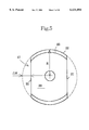
- FIG. 5 is a view shown from an arrow Z of FIG. 4 for a medium to high frequency device thereof;
- FIG. 6 is a view equivalent to FIG. 1 according to the fourth embodiment.
- FIG. 7 is a graph showing the dynamic spring characteristic according to the third and fourth embodiments.
- FIG. 8 is a general sectional view equivalent to a view taken along line 8--8 of FIG. 10 according to the fifth embodiment
- FIG. 9 is a general sectional view equivalent to a view taken along line 8-9 of FIG. 10 according to the fifth embodiment.
- FIG. 10 is a plan view of an engine mount
- FIG. 11 is a view showing a plan viewed shape of a first and second orifice passages
- FIG. 12 is a sectional view of a driving portion
- FIG. 13 is a view showing such as a side shape of a cylindrical covering portion
- FIG. 14 is an enlarged sectional view of a principal portion
- FIG. 15 is a view showing an assembling process of the device.
- FIG. 16 a graph showing the dynamic spring characteristic according to the fifth embodiment.
- FIG. 1 is a general sectional view of an engine mount according to the first embodiment of the present invention (sectional view along line 1--1 direction of the FIG. 2), FIG. 2 is a rough plan view of an elastic member and FIG. 3 is a graph showing a dynamic spring characteristic, wherein the axis of abscissa shows frequency and the axis of ordinates shows a dynamic spring constant.
- the engine mount comprises a first support member 1 attached to an engine side as a vibration source, a second support member 2 attached to a vehicle body and a resilient member 3 interposed between the first support member 1 and the second support member 2.
- the first support member 1 is made to be in a shaft shape extending into the second support member 2 in parallel to an input direction X of a principal vibration.
- the resilient member 3 is formed from a suitable elastic material such as rubber or elastomer and formed integrally with a conical portion 4 formed in a generally conical shape and a cylindrical portion 5.
- a pair of recesses 6 are formed in the same shape at an axis-symmetrical position and the conical portion 4 of the recess 6 is arranged to be a thin wall portion 7.
- the recess 6 is formed continuing until inside of the cylindrical portion 5.
- the cylindrical portion 5 is integrated to an inside face of a cylindrical covering portion 8 of the second support member 2 and forms a liquid chamber inside thereof with a diaphragm 9 fixed to the inside of the cylindrical portion 8 and the resilient member 3.
- This liquid chamber is divided to a main liquid chamber 11 of the first support member side and an auxiliary liquid chamber 12 of the diaphragm 9 side by a partition member 10 provided on an inner side than the diaphragm 9 and the two liquid chambers are communicated by an orifice passage 14 formed between the partition member 10 and a rim portion 13 of the diaphragm 9.
- the orifice passage 14 is communicated with the main liquid chamber 11 at an inlet 15 formed in the partition member 10 and communicated with the auxiliary liquid chamber 12 at an outlet 16 formed on the resilient member 3.
- the first support member 1 is extended along a center line of the resilient member 3 and an end thereof is projected into the main liquid chamber 11, thereon a generally cup shaped medium to high frequency device 17 is fixed by caulking.
- the medium to high frequency device 17 is formed in a circular shape viewed from an axial direction of the first support member 1.
- a designated orifice gap 18 is formed and is adapted to absorb the vibration input of the high frequency range by the liquid column resonance.
- the thin wall portion 7 is adapted to absorb the vibration input of the designated medium to high frequency range by the membrane resonance owing to changing thickness and area of the membrane through controlling the size and depth of the recess 6.
- the thin wall portion 7 when a vibration of the medium to high frequency range is inputted, the thin wall portion 7 generates the membrane resonance and the dynamic spring constant yields the minimum value A at beforehand set designated frequency.
- the dynamic spring constant yields a minimum value B at another designated frequency f2 by the liquid column resonance in the orifice gap 18 between the thin wall portion 7 and the inner face of the conical portion 4.
- the characteristic curve 2 in FIG. 3 is relating to the second embodiment which is an example that is provided as shown by a broken line in only one side of the thin wall portion 7 in FIG. 2 where the thin wall emphasis portion 19a is provided to make the thickness thereof thinner by forming the deep recess 19, and the thin wall portion 7 by the recess 6 and the thin wall emphasis portion 19a by the deep recess 19 are arranged to be the symmetrical thin wall portion different in shape.
- the resilient member 3 is formed as this, because the membrane resonance frequencies in the thin wall portion 7 and the thin wall emphasis portion 19a are mutually different, two minimum values C and D occur in the medium to high frequency range which result in that the lower dynamic spring constant can be realized.
- FIGS. 4 and 5 are views showing the third embodiment
- FIG. 4 is a view equivalent to FIG. 1 of the former embodiment
- FIG. 5 is a view showing the medium to high frequency device from Z arrow direction thereof.
- this embodiment is one merely changed a part of the former embodiment
- common numerals are used for common portions an explanation of similar repetition is omitted as much as possible and for the explanation portion omitted, an explanation relating to the equivalent portion of the former embodiment is quoted (same for the embodiment hereinafter).
- each of the succeeding embodiments incorporates the use of a medium to high frequency device 17 and at least one thin walled portion 7 formed by a respective recess 6.
- the medium to high frequency device 17 relating to the third embodiment is formed in a non-circular shape and the designated orifice gap 18 is formed between the inside face of the conical portion of the resilient member 3 and therewith so as to absorb the vibration input in the high frequency range by the liquid column resonance.
- the recesses 6 relating to the present embodiment are symmetrically formed thereon at the different place by 180 degrees as similar as shown in FIG. 2.
- the thin wall portion 7 is adapted to absorb the vibration input of the specified medium frequency range by the membrane resonance through changing the thickness and area of the membrane owing to the controlling the dimension and depth of the recess 6.
- FIG. 5 is a view seeing from the arrow Z direction of FIG. 4, namely a parallel direction to an input direction X of the principal vibration.
- the medium to high frequency device 17 is made in a generally oval shape and a pair of cut out portions 21 are formed at symmetrical positions.
- This cut out portion 21 corresponds to the shape cut out from a portion facing the thin wall portion 7 by ⁇ R part among the main body 20 constructed originally as a circle having a radius R in an arrow Z direction.
- a flange 23 is formed on an arcuate portion 22 having a radius R in the 90 degree different direction therewith.
- a projection area of the medium to high frequency device 17 in an axial line direction of the first support member 1 becomes smaller than that in a case whole body is constructed as a circle having a radius R and the flow volume of the liquid owing to the medium to high frequency device 17 is as much reduced.
- a space as a gap d1 is formed between the cut out portion 21 and the thin wall portion 7 and a space as a gap d2 is also formed between the arcuate portion 22 and the rubber inner wall 24 facing therewith.
- d1 is arranged to be by far larger than d2.
- FIG. 7, 1 is a characteristic curve relating to the first embodiment of the first invention and 3 is a characteristic curve of the third invention (namely the present third embodiment).
- the thin wall portion When the vibration of the medium frequency range is inputted, the thin wall portion generates the membrane resonance and a minimum value A is yielded at the beforehand set specified frequency.
- a minimum value B is yielded at a specified frequency by the liquid column resonance in the orifice gap 18 between the thin wall portion 7 and the inner face of the conical portion 4.
- the resonance frequency becomes higher than the case in which the circular medium to high frequency device is used as shown by a characteristic curve of a phantom line as a comparative example.
- a liquid resonance energy becomes small and approaches the resonance energy of the membrane resonance.
- the fourth embodiment is shown, namely, the resilient partition wall is provided on a lower portion of the engine mount in the first embodiment.
- a resilient partition wall 31 made of the elastic membrane such as rubber and the like is faced to a hole 30 formed in the center portion of the ring shaped partition member 10.
- a bottom peripheral portion of a resilient partition wall 31 is made to be integrated thick portion 32 and on a bottom portion thereof, a leg portion 33 is formed together to deform according to the deforming of the resilient partition wall 31.
- a part of the resilient wall 31 facing the hole 30 is arranged to be a thin wall portion against the thick wall portion 32 and functions as a kind of a rubber spring owing to possessing spring property. Which is resiliently deformed according to the inner pressure change of the main liquid chamber 11 and is adapted to membrane resonate.
- the leg portion 33 is abutted to a wall portion 35 integrally formed with a lower support member 34 and renders a non-linear spring characteristic for the deformation of the resilient partition wall 31.
- the lower support member 34 is a resin made member supporting a bottom portion of an outer peripheral side of the thick wall portion 32 and the wall portion 35 is formed to crook upward generally in perpendicular from the inner peripheral side thereof.
- the wall portion 35 is fitted into a ring groove 36 formed on a bottom portion of the thick wall portion 32 and a side abutting to the wall portion 35 of the leg portion 33 is separated from other thick wall portion 32 by the ring groove 36 so as to freely move.
- Numeral 9 in the drawing shows a diaphragm and the orifice passage 14 is formed within thickness of the thick wall portion 32 in a circumferential direction and communicates the main liquid chamber 11 and the auxiliary liquid chamber 12.
- Numeral 1a is a resin made bracket integrated to a periphery of the first support member as a forged product.
- the resilient partition wall 31 since the resilient partition wall 31 absorbs the inner pressure of the main liquid chamber 11 by the resilient deforming for itself, the dynamic spring constant in the medium frequency range is reduced by ⁇ K comparing to the characteristic curve 1, 3. Further, the resilient partition wall 31 membrane-resonate by liquid flow in the main liquid chamber 11.
- the membrane resonance by the resilient partition wall 31 is complicated with the membrane resonance by the thin wall portion 7 in the conical portion 4 and the liquid column resonance owing to the medium to high frequency device 17, the minimum values A, B and the peak of the dynamic spring constant between A, B as shown in the characteristic curve 1 to 3 are gently smoothed and remarkably low dynamic spring characteristics are attained over the approximately entire frequency range of the medium to high frequency.
- FIG. 8 is a general sectional view equivalent to a view taken along line 8--8 of FIG. 10
- FIG. 9 is a general view equivalent to a view taken along line 8-9 of FIG. 10
- FIG. 10 is a plan view of an engine mount
- FIG. 11 is a view showing a plan viewed shape of a first and second orifice passages
- FIG. 12 is a sectional view of a switching valve
- FIG. 13 is a view showing such as a side shape of a cylindrical covering portion
- FIG. 14 is an enlarged sectional view of a principal portion
- FIG. 15 is a view showing an assembling process of the device
- FIG. 16 is a characteristic curve of the present embodiment showing together with other comparative example.
- the present embodiment is equivalent to one adopting an elastic control mechanism using a switching valve instead of the resilient partition wall in the former embodiment.
- This elastic control mechanism 40 is assembled from a orifice portion 41 and a driving portion 42, the orifice portion 41 comprises a cylindrical upper cup-like member 43, a circular and thick orifice member 44 fitted inside thereof, a disk-like cover 45 being covered thereon and a diaphragm 50 forming the auxiliary chamber 12 between the orifice member and therewith.
- a first orifice passage 46 corresponding to the damping orifice similar to the orifice passage 14 of the each former embodiment to contribute for the vibration damping in the low frequency range and the second orifice passage 47 arranged to be the orifice passage for the specified frequency are provided.
- first orifice passage 46 communicates with the main liquid chamber 11 and the auxiliary liquid chamber 12 at the not shown opening extending spirally in the thickness of the orifice member 44 along the neighbor of the outer periphery thereof.
- numeral 46a is an inlet of the first orifice passage 46 made to be a slope enlarged toward a flow in side
- 46b is an outlet thereof
- 47a is an inlet of the second orifice passage 47.
- a sectional line is also expressed to show the section of FIG. 8 and FIG. 9 corresponding to FIG. 10.
- the second orifice passage 47 is formed passing through both sides of the orifice member 44 inside of the first orifice passage 46 and a guide slope 48 is formed toward an outlet 49 formed in the about center portion of the upper cup-like member 43 to make the slant flow line for the liquid flowing out from the outlet 49.
- the shape of the opening portion of the outlet 49 is made also to be asymmetric to the center line C and is opened widely toward the flow line direction by the guide slope 48.
- This outlet 49 is adapted to be freely opened and closed by an open and close portion 51 formed integrally at a center portion of a diaphragm 50.
- the diaphragm 50 is similar to one of the former each embodiment but different in a point that it is provided integrally with the open and close portion 51 arranged to be a flat contact surface at the center portion thereof to seat tightly on a periphery of the outlet 49. Opening of the open and close portion 51 can be assured through the liquid flowing out from the outlet 49 pushing an offset position from a center by the slant flow line.
- the driving portion 42 comprises a lower cup-like member 52 and a switching valve 54 fitted inside thereof to form a sealed space 53, a seat portion 54a to be a top portion of the switching valve 54 abuts to the open and close portion 51.
- the switching valve 54 is urged to a closed direction by a return spring 55 and make the switching valve 54 to move against the return spring 55 by connecting the inside of the sealed space 53 to a not shown negative pressure supply through a joint pipe 56 for making the open and close portion 51 free to open an outlet 49 of the second orifice passage 47.
- Open and close of the switching valve 54 is possible to be set for an optional specified frequency, but in the present embodiment, it is set for a frequency while engine idling so the second orifice passage 47 is adapted to be an idling orifice.
- open and close of the switching valve 54 is possible not only by utilizing such a negative pressure but also by various known methods such as electromagnetic type.
- the lower cup-like member 52 comprises a cup-like metal 57 on a center bottom portion thereof formed a large opening and a resin portion 58 formed integrally with the joint pipe 56 to cover the bottom portion from a side lower half portion thereof, and a fixing ring 60 is fitted by a pressure fitting to an inside of a peripheral portion of the cup-like metal 57 to fix the switching valve 54.
- FIG. 12 is an enlarged view of a section of the switching valve 54 in FIG. 8.
- the switching valve 54 is made to be about up side down cup-like and a membrane member 61 made from elastic member such as rubber connects between the flange portion 54b formed on a lower portion thereof and the fixing ring 60.
- the membrane member 61 does not possess a spring elasticity affecting to an operation of the switching valve 54.
- a part of a membrane member 61 integrated to cover the fixing ring 60 is made to be an upper end covering portion 61b covering an upper end portion of a small diameter portion 60a formed on an upper portion of the fixing ring 60 and come to the outer side therefrom to be an outer periphery covering portion 61a.
- the outer periphery covering portion 61a and the upper end covering portion 61b are formed on the whole circumference and these parts compose the ring portion elastic member of the present invention.
- a first seal lip 62a is integrally formed to project to the radial direction.
- a second seal lip 62b is formed to project downward from a lower end portion of the membrane member 61 inside the lower end portion of the fixing ring 60 a second seal lip 62b is formed to project downward.
- These seal lips are respectively formed on the whole circumference.
- a downward extension portion 8a which is adapted to be a part of the cylindrical portion 8 and extends downward longer than the elastic member 3, possesses a large diameter portion 8b accommodating the orifice portion 41 thereon, and fixes the orifice portion 41 by a first caulking portion 63 formed on a lower end portion of the large diameter portion 8b.
- the positioning ring 64 is adapted to be a step portion 65 at a lower portion of the upper cup-like member 43 and a lower portion than the step portion 65 is made to be a small diameter portion having an outer diameter with the same extent as the inner periphery of the cup-like metal 57.
- an outer peripheral portion of the diaphragm 50 and an outer periphery of a bottom portion of the upper cup-like member 43 are supported in an inside of the step portion 65 and are caulked from the outside thereof by the first caulking portion 63 which resulted in that the step portion 65 make the outer periphery of the diaphragm 50 to stick to the bottom portion of the upper cup-like portion 43, liquid tightness of the auxiliary liquid chamber 12 and the main liquid chamber 11 are assured.
- a lower end portion of the positioning ring 64 is adapted to be a flange portion 66 bending inward and is positioned by abutting elastically to an upper end covering portion 61b which is a part of the membrane member 61 and covers an upper end portion of the fixing ring 60.
- an upper end portion of the cup-like metal 57 extends also to a vicinity of the step portion 65 where it is adapted to be a flange portion 67 bending outward and is fixed by a second caulking portion 68 provided to the large diameter portion 8b. Between a flange portion of the cup-like metal 57 and the first caulking portion 63, a small gap is formed (see FIG. 8).
- FIG. 13 is a view showing a side shape of the cylindrical covering portion 8 before connecting with the driving portion 42 from an arrow Y direction of FIG. 10.
- the cylindrical covering portion 8 is shown in a state integrating the upper construction such as the elastic member 3 and on a lower portion of the large diameter portion 8b, a first claw 63a and a second claw 68a are provided projecting downward.
- the first and second claws 63a and 68a are parts to form the first and second caulking portions 63 and 68 by bending the lower end portions thereof, either parts are made to have different height by changing the downward projecting amount on the lower end portion of the large diameter portion 8b and formed alternately at suitable intervals to a circumferential direction.
- FIG. 14 is an enlarged view of F portion in FIG. 8.
- an outer diameter of a lower portion of the fixing ring 60 is smaller than an inner diameter of the cup-like metal 57 and between both members some amount gap 70 is arranged.
- a radial direction ventilation groove 71 is formed at suitable intervals to a circumferential direction and communicates the inner space 76 between the switching valve 54 and the diaphragm 50 with the atmosphere through an atmosphere opening hole 72 formed to pass through the cup-like metal 57 in the vicinity thereof.
- the diameter is further reduced and arranged to be a step portion 74 forming a small gap 73 between the inner periphery of the cup-like metal and therewith, where a through hole 75 is provided.
- the inner space 76 communicates with the atmosphere opening hole 72 between the switching valve 54 and the diaphragm 50 through said through hole 75.
- a lower portion of the atmosphere opening hole 72 is provided on a lower position than the ventilation groove 71.
- FIG. 15 shows an assembling process of the elastic control mechanism 40, first the orifice portion 41 is accommodated in the large diameter portion 8b and is caulked by the first caulking portion 63, by which the liquid sealed mount portion is integrated to be a sub-assembly.
- the second caulking portion 68 is caulked to the flange portion 67, which makes the whole assembly.
- the positioning ring 64 can decide a mounting position of the driving portion 42 to the orifice portion 41, the positioning ring 64 is elastically pressed against the fixing ring 60 side through the upper end covering portion 61b. Even if there is some amount of dimensional error, a gap 69 between the first caulking portion 63 and the flange portion 67 of the cup-like metal 57 allows it to be easily absorbed.
- each of the embodiments of the present invention incorporates the use of a medium to high frequency device 17 and at least one thin walled portion 7 formed by a respective recess 6.
- the characteristic curve in the medium to high frequency range becomes 5 of FIG. 16 and is approximately similar to the characteristic of the third embodiment (3 of FIG. 7) in this region.
- the switching valve 54 is lowered and the second orifice passage 47 is communicated with the auxiliary liquid chamber 12 through detaching the open and close portion 51 from the outlet 49, as is shown in the drawing, the dynamic spring constant in the idling range is abruptly reduced and can be lower than that of 4 in FIG. 7.
- the low dynamic spring constant can be realized in the almost entire range over the low frequency, the medium frequency and the high frequency, additionally, because the further low dynamic spring constant can be achieved in the designated frequency by the elastic control mechanism.
- this designated frequency can be optionally set in the almost entire frequency range from the low frequency range to the high frequency range.
- 6 and 7 are the dynamic spring characteristics of the comparative examples relating to the liquid sealed mount
- the elastic mount of each liquid sealed mount thereof is a type not provided with the thin wall portion by the recess such as present invention having the medium to high frequency device
- 6 is an example using the elastic partition member as shown in the embodiment of FIG. 6
- 7 is an example using the elastic control mechanism same as the present embodiment.
- Either examples are provided with the damping orifice for the low frequency range, but are not constructed to produce the membrane resonance in the medium frequency region and the liquid column resonance in the high frequency range as the present invention, and are almost the same as the conventional example in FIG. 3.
- switching of the orifice passage in the idling region is practiced in the idling region by the same mechanism, either characteristics coincidences merely in this portion.
- the orifice portion 41 in which the liquid is sealed and the driving portion 42 actuating the valve by the negative pressure are separated and are made to be individually secured in different processes, it can be surely prevented that the sealed liquid invades into the driving portion 42 side and reaches to the driving center portion such as the negative pressure tank. Consequently, the quality of the products can be improved, at the same time, the assembling process becomes easier.
- the orifice portion 41 and the driving portion 42 can be fixed by the first caulking portion 63 and the second caulking portion 68 owing to two kind of the first and the second claws 63a and 68a provided on the large diameter portion 8b, the number of the parts can be decreased, the fixing construction and the assembling process can be simplified.
- the positioning ring 64 can decide the mounting position of the driving portion 42 to the orifice portion 41. Therefore, the dimensional control can be more roughly practiced than the former one, the assembling process becomes easy and a reduction of costs can be carried out.
- the fixing ring 60 fixing the switching valve 54 and the inside face of the cup-like metal 57 and the fixing ring 60 is arranged to fit into the inside of the cup-like metal 57 via the elasticity of the outer periphery covering portion 61a, when the fixing ring 60 is fitted into the cup-like metal 57, it can be done with the light load hence a capital investment in a press machine can be decreased.
- the fixing ring 60 is pressed against the inside of the cup-like metal 57 by the first seal lip 62a and also pressed against the bottom portion of the cup-like metal 57 by the second seal lip 62b, which result in that the fixing ring 60 possesses a double seal construction to the cup-like metal 57, that makes the air-tightness higher in the sealed space 53 applied with the negative pressure and the operational accuracy of the device can be improved.
- the ventilation groove 71 and the through hole 75 communicate with the atmosphere opening hole 72 through the gap 73 formed on the whole circumference, the air in the inner space 76 between the switching valve 54 and the diaphragm 50 can be released to the atmosphere. Consequently, it can displayed the most of an orifice resonance effect through making the movement of the diaphragm 50 smooth. Also, since the atmospheric pressure can be maintained from the above discussed reason even if the thermal expansion or contraction of the air is generated, the performance of the device can be stabilized through reducing the effect to the characteristics by thermal change. Besides, since the lower portion of the atmosphere opening hole 72 is provided on the lower position than the ventilation groove 71, the water entering from the atmosphere opening hole 72 is hard to gather in the ventilation groove 71 and the through hole 75.
- the ventilation groove 71 and the through hole 75 can communicate with the atmosphere opening hole 72 via the gap 73 even if fixing ring 60 and the positioning ring 64 are respectively situated on any place to the cup-like metal 57 in the circumferential direction. Accordingly, since the fixing ring 60 and the positioning ring 64 can be respectively positioned freely to the cup-like metal 57 in the circumferential direction, assembling performance can be improved.
- the medium to high frequency device of the second embodiment can be combine to the third embodiment.
- the medium to high frequency device of the first embodiment can be combined to the fifth embodiment.
Landscapes
- Engineering & Computer Science (AREA)
- General Engineering & Computer Science (AREA)
- Mechanical Engineering (AREA)
- Combined Devices Of Dampers And Springs (AREA)
- Arrangement Or Mounting Of Propulsion Units For Vehicles (AREA)
Priority Applications (2)
| Application Number | Priority Date | Filing Date | Title |
|---|---|---|---|
| US09/131,839 US6131894A (en) | 1998-08-10 | 1998-08-10 | Liquid sealed type rubber mount device |
| EP98306479A EP0980990B1 (de) | 1998-08-10 | 1998-08-14 | Flüssigkeitsabgedichtete, elastische Lagerungsvorrichtung |
Applications Claiming Priority (2)
| Application Number | Priority Date | Filing Date | Title |
|---|---|---|---|
| US09/131,839 US6131894A (en) | 1998-08-10 | 1998-08-10 | Liquid sealed type rubber mount device |
| EP98306479A EP0980990B1 (de) | 1998-08-10 | 1998-08-14 | Flüssigkeitsabgedichtete, elastische Lagerungsvorrichtung |
Publications (1)
| Publication Number | Publication Date |
|---|---|
| US6131894A true US6131894A (en) | 2000-10-17 |
Family
ID=26151395
Family Applications (1)
| Application Number | Title | Priority Date | Filing Date |
|---|---|---|---|
| US09/131,839 Expired - Lifetime US6131894A (en) | 1998-08-10 | 1998-08-10 | Liquid sealed type rubber mount device |
Country Status (2)
| Country | Link |
|---|---|
| US (1) | US6131894A (de) |
| EP (1) | EP0980990B1 (de) |
Cited By (12)
| Publication number | Priority date | Publication date | Assignee | Title |
|---|---|---|---|---|
| US6267362B1 (en) * | 1999-02-10 | 2001-07-31 | Yamashita Rubber Kabushiki Kaisha | Liquid sealed type elastic mount |
| US6311963B1 (en) * | 1998-12-22 | 2001-11-06 | Tokai Rubber Industries, Ltd. | Fluid-filled vibration damping device |
| US6439554B1 (en) * | 1999-05-27 | 2002-08-27 | Toyo Tire & Rubber Co., Ltd. | Switchable liquid-filled vibration isolating mount |
| US6592110B2 (en) | 2000-02-01 | 2003-07-15 | Toyo Tire & Rubber Co., Ltd. | Switchable liquid-filled vibration absorbing mount |
| US20040145125A1 (en) * | 2001-06-22 | 2004-07-29 | Kazutoshi Satori | Liquid ring vibration control device |
| US20050001364A1 (en) * | 2003-06-20 | 2005-01-06 | Herve Visage | Hydraulic antivibration support |
| US20060091594A1 (en) * | 2004-11-04 | 2006-05-04 | Honda Motor Co., Ltd. | Vibration-proof apparatus for vehicle |
| US20060261529A1 (en) * | 2004-12-24 | 2006-11-23 | Hikofumi Yamamoto | Hydraulic antivibration device arrangement, hydraulic antivibration device, and car body side bracket |
| US20120091642A1 (en) * | 2009-04-27 | 2012-04-19 | Bridgestone Corporation | Vibration absorption device |
| JP2012137152A (ja) * | 2010-12-27 | 2012-07-19 | Bridgestone Corp | 防振装置 |
| US20190277362A1 (en) * | 2018-03-12 | 2019-09-12 | Sumitomo Riko Company Limited | Vibration damping device |
| US11472279B2 (en) * | 2019-09-27 | 2022-10-18 | Hyundai Motor Company | Mount for vehicle |
Families Citing this family (1)
| Publication number | Priority date | Publication date | Assignee | Title |
|---|---|---|---|---|
| JP3590904B2 (ja) * | 2001-04-16 | 2004-11-17 | 東洋ゴム工業株式会社 | 防振装置 |
Citations (15)
| Publication number | Priority date | Publication date | Assignee | Title |
|---|---|---|---|---|
| GB2055172A (en) * | 1979-06-29 | 1981-02-25 | Gomma Antivibranti Applic | Elastomeric mounting with fluid damping of high amplitude oscillations |
| JPS60104824A (ja) * | 1983-11-09 | 1985-06-10 | Honda Motor Co Ltd | 流体入りエンジンマウント |
| JPS6223178A (ja) * | 1985-07-23 | 1987-01-31 | Nec Corp | 半導体集積回路 |
| DE8623498U1 (de) * | 1986-09-02 | 1988-05-26 | Adam Opel AG, 6090 Rüsselsheim | Zweikammerlager |
| EP0271894A2 (de) * | 1986-12-19 | 1988-06-22 | METZELER Gesellschaft mit beschränkter Haftung | Hydraulisch dämpfendes Motorlager |
| US4826126A (en) * | 1987-08-11 | 1989-05-02 | Tokai Rubber Industries, Ltd. | Fluid-filled elastic mounting structure |
| US4889325A (en) * | 1988-08-15 | 1989-12-26 | Lord Corporation | Fluid filled vibration isolator |
| US4997168A (en) * | 1988-08-23 | 1991-03-05 | Tokai Rubber Industries, Ltd. | Fluid-filled elastic mount |
| US5104100A (en) * | 1989-11-09 | 1992-04-14 | Firma Carl Freudenberg | Rubber mount with hydraulic damping |
| DE4036517A1 (de) * | 1990-11-16 | 1992-05-21 | Phoenix Ag | Elastisches lager |
| EP0534124A1 (de) * | 1991-09-24 | 1993-03-31 | Metzeler Gimetall Ag | Elastisches Motorlager |
| US5433421A (en) * | 1991-07-08 | 1995-07-18 | Bridgestone Corporation | Vibration isolating apparatus |
| US5501433A (en) * | 1993-07-06 | 1996-03-26 | Yamashita Rubber Kabushiki Kaisha | Liquid sealing and vibration isolator |
| US5667205A (en) * | 1995-03-22 | 1997-09-16 | Yamashita Rubber Kabushiki Kaisha | Fluid-sealed type anti-vibration rubber device |
| US5772189A (en) * | 1995-06-15 | 1998-06-30 | Yamashita Rubber Kabuskiki Kaisha | Antivibration rubber device |
-
1998
- 1998-08-10 US US09/131,839 patent/US6131894A/en not_active Expired - Lifetime
- 1998-08-14 EP EP98306479A patent/EP0980990B1/de not_active Expired - Lifetime
Patent Citations (15)
| Publication number | Priority date | Publication date | Assignee | Title |
|---|---|---|---|---|
| GB2055172A (en) * | 1979-06-29 | 1981-02-25 | Gomma Antivibranti Applic | Elastomeric mounting with fluid damping of high amplitude oscillations |
| JPS60104824A (ja) * | 1983-11-09 | 1985-06-10 | Honda Motor Co Ltd | 流体入りエンジンマウント |
| JPS6223178A (ja) * | 1985-07-23 | 1987-01-31 | Nec Corp | 半導体集積回路 |
| DE8623498U1 (de) * | 1986-09-02 | 1988-05-26 | Adam Opel AG, 6090 Rüsselsheim | Zweikammerlager |
| EP0271894A2 (de) * | 1986-12-19 | 1988-06-22 | METZELER Gesellschaft mit beschränkter Haftung | Hydraulisch dämpfendes Motorlager |
| US4826126A (en) * | 1987-08-11 | 1989-05-02 | Tokai Rubber Industries, Ltd. | Fluid-filled elastic mounting structure |
| US4889325A (en) * | 1988-08-15 | 1989-12-26 | Lord Corporation | Fluid filled vibration isolator |
| US4997168A (en) * | 1988-08-23 | 1991-03-05 | Tokai Rubber Industries, Ltd. | Fluid-filled elastic mount |
| US5104100A (en) * | 1989-11-09 | 1992-04-14 | Firma Carl Freudenberg | Rubber mount with hydraulic damping |
| DE4036517A1 (de) * | 1990-11-16 | 1992-05-21 | Phoenix Ag | Elastisches lager |
| US5433421A (en) * | 1991-07-08 | 1995-07-18 | Bridgestone Corporation | Vibration isolating apparatus |
| EP0534124A1 (de) * | 1991-09-24 | 1993-03-31 | Metzeler Gimetall Ag | Elastisches Motorlager |
| US5501433A (en) * | 1993-07-06 | 1996-03-26 | Yamashita Rubber Kabushiki Kaisha | Liquid sealing and vibration isolator |
| US5667205A (en) * | 1995-03-22 | 1997-09-16 | Yamashita Rubber Kabushiki Kaisha | Fluid-sealed type anti-vibration rubber device |
| US5772189A (en) * | 1995-06-15 | 1998-06-30 | Yamashita Rubber Kabuskiki Kaisha | Antivibration rubber device |
Non-Patent Citations (2)
| Title |
|---|
| PATENT ABSTRACTS OF JAPAN vol. 009, no. 256 (M-421), 15 October 1985 & JP 60 104824 A (HONDA GIKEN KOGYO KK), 10 June 1985 … * |
| Patent Abstracts of Japan, JP 30 104824 A, vol. 009, No. 256, Honda Giken Kogyo Kabushiki Kaisha, (Jun. 10, 1985). |
Cited By (17)
| Publication number | Priority date | Publication date | Assignee | Title |
|---|---|---|---|---|
| US6311963B1 (en) * | 1998-12-22 | 2001-11-06 | Tokai Rubber Industries, Ltd. | Fluid-filled vibration damping device |
| US6267362B1 (en) * | 1999-02-10 | 2001-07-31 | Yamashita Rubber Kabushiki Kaisha | Liquid sealed type elastic mount |
| US6439554B1 (en) * | 1999-05-27 | 2002-08-27 | Toyo Tire & Rubber Co., Ltd. | Switchable liquid-filled vibration isolating mount |
| US6592110B2 (en) | 2000-02-01 | 2003-07-15 | Toyo Tire & Rubber Co., Ltd. | Switchable liquid-filled vibration absorbing mount |
| US7159856B2 (en) * | 2001-06-22 | 2007-01-09 | Honda Motor Co., Ltd. | Fluid sealed antivibration device |
| US20040145125A1 (en) * | 2001-06-22 | 2004-07-29 | Kazutoshi Satori | Liquid ring vibration control device |
| US20050001364A1 (en) * | 2003-06-20 | 2005-01-06 | Herve Visage | Hydraulic antivibration support |
| US20060091594A1 (en) * | 2004-11-04 | 2006-05-04 | Honda Motor Co., Ltd. | Vibration-proof apparatus for vehicle |
| US7458565B2 (en) * | 2004-11-04 | 2008-12-02 | Honda Motor Co., Ltd. | Vibration-proof apparatus for vehicle |
| US20060261529A1 (en) * | 2004-12-24 | 2006-11-23 | Hikofumi Yamamoto | Hydraulic antivibration device arrangement, hydraulic antivibration device, and car body side bracket |
| US7278633B2 (en) * | 2004-12-24 | 2007-10-09 | Toyo Tire & Rubber Co., Ltd. | Hydraulic antivibration device arrangement, hydraulic antivibration device, and car body side bracket |
| US20120091642A1 (en) * | 2009-04-27 | 2012-04-19 | Bridgestone Corporation | Vibration absorption device |
| US9903437B2 (en) * | 2009-04-27 | 2018-02-27 | Bridgestone Corporation | Vibration absorption device |
| JP2012137152A (ja) * | 2010-12-27 | 2012-07-19 | Bridgestone Corp | 防振装置 |
| US20190277362A1 (en) * | 2018-03-12 | 2019-09-12 | Sumitomo Riko Company Limited | Vibration damping device |
| US10794446B2 (en) * | 2018-03-12 | 2020-10-06 | Sumitomo Riko Company Limited | Vibration damping device |
| US11472279B2 (en) * | 2019-09-27 | 2022-10-18 | Hyundai Motor Company | Mount for vehicle |
Also Published As
| Publication number | Publication date |
|---|---|
| EP0980990B1 (de) | 2004-10-27 |
| EP0980990A1 (de) | 2000-02-23 |
Similar Documents
| Publication | Publication Date | Title |
|---|---|---|
| US6267362B1 (en) | Liquid sealed type elastic mount | |
| US6131894A (en) | Liquid sealed type rubber mount device | |
| EP0930447B1 (de) | Schwingungsdämpfende Vorrichtung mit Flüssigkeitskammern auf gegenüberliegenden Seiten einer Partitionsstruktur mit bewegbarer Gummiplatte | |
| US8297602B2 (en) | Vibration isolator | |
| US5667205A (en) | Fluid-sealed type anti-vibration rubber device | |
| US4907786A (en) | Fluid-filled elastic mount having partition member which includes a double-layered section | |
| US20240376954A1 (en) | Shock absorber | |
| US20020145240A1 (en) | Fluid-sealed anti-vibration device | |
| US8770559B2 (en) | Liquid sealed vibration isolating device | |
| JP4220107B2 (ja) | 制御型の液封入式防振装置 | |
| EP0984192B1 (de) | Flüssigkeitsabgedichteter Schwingungstilger | |
| US6523813B1 (en) | Fluid-filled vibration damping device | |
| US6755401B2 (en) | Fluid-filled vibration damping device | |
| JP3542063B2 (ja) | 液封マウント | |
| US6032935A (en) | Liquid enclosing type vibration isolating mount | |
| JP4039827B2 (ja) | 液封マウント | |
| JP4202484B2 (ja) | 液封マウント | |
| US6170810B1 (en) | Liquid sealed type bushing | |
| JP4393695B2 (ja) | 液封防振装置 | |
| US20250215953A1 (en) | Liquid seal type vibration isolation device | |
| JP4011954B2 (ja) | 流体封入式防振装置 | |
| JP3146193B2 (ja) | 液封マウント | |
| JP4358417B2 (ja) | 液封防振装置 | |
| JP2019074173A (ja) | 流体封入式防振装置 | |
| WO2023199648A1 (ja) | 緩衝器 |
Legal Events
| Date | Code | Title | Description |
|---|---|---|---|
| AS | Assignment |
Owner name: YAMASHITA RUBBER KABUSHIKI KAISHA, JAPAN Free format text: ASSIGNMENT OF ASSIGNORS INTEREST;ASSIGNORS:SATORI, KAZUTOSHI;NINAKAWA, OSAMU;REEL/FRAME:009552/0847 Effective date: 19980826 |
|
| STCF | Information on status: patent grant |
Free format text: PATENTED CASE |
|
| FPAY | Fee payment |
Year of fee payment: 4 |
|
| FPAY | Fee payment |
Year of fee payment: 8 |
|
| FPAY | Fee payment |
Year of fee payment: 12 |