US6083228A - Device and method for preparing a space between adjacent vertebrae to receive an insert - Google Patents
Device and method for preparing a space between adjacent vertebrae to receive an insert Download PDFInfo
- Publication number
- US6083228A US6083228A US09/094,036 US9403698A US6083228A US 6083228 A US6083228 A US 6083228A US 9403698 A US9403698 A US 9403698A US 6083228 A US6083228 A US 6083228A
- Authority
- US
- United States
- Prior art keywords
- abrading
- abrading element
- drive mechanism
- shaft
- mounting member
- Prior art date
- Legal status (The legal status is an assumption and is not a legal conclusion. Google has not performed a legal analysis and makes no representation as to the accuracy of the status listed.)
- Expired - Lifetime
Links
Images


Classifications
-
- A—HUMAN NECESSITIES
- A61—MEDICAL OR VETERINARY SCIENCE; HYGIENE
- A61B—DIAGNOSIS; SURGERY; IDENTIFICATION
- A61B17/00—Surgical instruments, devices or methods, e.g. tourniquets
- A61B17/16—Bone cutting, breaking or removal means other than saws, e.g. Osteoclasts; Drills or chisels for bones; Trepans
- A61B17/1662—Bone cutting, breaking or removal means other than saws, e.g. Osteoclasts; Drills or chisels for bones; Trepans for particular parts of the body
- A61B17/1671—Bone cutting, breaking or removal means other than saws, e.g. Osteoclasts; Drills or chisels for bones; Trepans for particular parts of the body for the spine
-
- A—HUMAN NECESSITIES
- A61—MEDICAL OR VETERINARY SCIENCE; HYGIENE
- A61B—DIAGNOSIS; SURGERY; IDENTIFICATION
- A61B17/00—Surgical instruments, devices or methods, e.g. tourniquets
- A61B17/16—Bone cutting, breaking or removal means other than saws, e.g. Osteoclasts; Drills or chisels for bones; Trepans
- A61B17/1659—Surgical rasps, files, planes, or scrapers
-
- A—HUMAN NECESSITIES
- A61—MEDICAL OR VETERINARY SCIENCE; HYGIENE
- A61B—DIAGNOSIS; SURGERY; IDENTIFICATION
- A61B17/00—Surgical instruments, devices or methods, e.g. tourniquets
- A61B17/16—Bone cutting, breaking or removal means other than saws, e.g. Osteoclasts; Drills or chisels for bones; Trepans
- A61B17/17—Guides or aligning means for drills, mills, pins or wires
- A61B17/1739—Guides or aligning means for drills, mills, pins or wires specially adapted for particular parts of the body
- A61B17/1757—Guides or aligning means for drills, mills, pins or wires specially adapted for particular parts of the body for the spine
-
- A—HUMAN NECESSITIES
- A61—MEDICAL OR VETERINARY SCIENCE; HYGIENE
- A61B—DIAGNOSIS; SURGERY; IDENTIFICATION
- A61B17/00—Surgical instruments, devices or methods, e.g. tourniquets
- A61B17/16—Bone cutting, breaking or removal means other than saws, e.g. Osteoclasts; Drills or chisels for bones; Trepans
- A61B17/1613—Component parts
- A61B17/1622—Drill handpieces
- A61B17/1624—Drive mechanisms therefor
-
- A—HUMAN NECESSITIES
- A61—MEDICAL OR VETERINARY SCIENCE; HYGIENE
- A61B—DIAGNOSIS; SURGERY; IDENTIFICATION
- A61B17/00—Surgical instruments, devices or methods, e.g. tourniquets
- A61B17/16—Bone cutting, breaking or removal means other than saws, e.g. Osteoclasts; Drills or chisels for bones; Trepans
- A61B17/1613—Component parts
- A61B17/1628—Motors; Power supplies
-
- A—HUMAN NECESSITIES
- A61—MEDICAL OR VETERINARY SCIENCE; HYGIENE
- A61B—DIAGNOSIS; SURGERY; IDENTIFICATION
- A61B17/00—Surgical instruments, devices or methods, e.g. tourniquets
- A61B17/16—Bone cutting, breaking or removal means other than saws, e.g. Osteoclasts; Drills or chisels for bones; Trepans
- A61B17/1662—Bone cutting, breaking or removal means other than saws, e.g. Osteoclasts; Drills or chisels for bones; Trepans for particular parts of the body
-
- A—HUMAN NECESSITIES
- A61—MEDICAL OR VETERINARY SCIENCE; HYGIENE
- A61B—DIAGNOSIS; SURGERY; IDENTIFICATION
- A61B17/00—Surgical instruments, devices or methods, e.g. tourniquets
- A61B2017/0046—Surgical instruments, devices or methods, e.g. tourniquets with a releasable handle; with handle and operating part separable
-
- A—HUMAN NECESSITIES
- A61—MEDICAL OR VETERINARY SCIENCE; HYGIENE
- A61B—DIAGNOSIS; SURGERY; IDENTIFICATION
- A61B17/00—Surgical instruments, devices or methods, e.g. tourniquets
- A61B2017/00477—Coupling
-
- A—HUMAN NECESSITIES
- A61—MEDICAL OR VETERINARY SCIENCE; HYGIENE
- A61B—DIAGNOSIS; SURGERY; IDENTIFICATION
- A61B17/00—Surgical instruments, devices or methods, e.g. tourniquets
- A61B2017/00535—Surgical instruments, devices or methods, e.g. tourniquets pneumatically or hydraulically operated
- A61B2017/00544—Surgical instruments, devices or methods, e.g. tourniquets pneumatically or hydraulically operated pneumatically
-
- A—HUMAN NECESSITIES
- A61—MEDICAL OR VETERINARY SCIENCE; HYGIENE
- A61B—DIAGNOSIS; SURGERY; IDENTIFICATION
- A61B17/00—Surgical instruments, devices or methods, e.g. tourniquets
- A61B2017/00681—Aspects not otherwise provided for
- A61B2017/00734—Aspects not otherwise provided for battery operated
-
- A—HUMAN NECESSITIES
- A61—MEDICAL OR VETERINARY SCIENCE; HYGIENE
- A61B—DIAGNOSIS; SURGERY; IDENTIFICATION
- A61B17/00—Surgical instruments, devices or methods, e.g. tourniquets
- A61B17/02—Surgical instruments, devices or methods, e.g. tourniquets for holding wounds open; Tractors
- A61B17/025—Joint distractors
- A61B2017/0256—Joint distractors for the spine
-
- A—HUMAN NECESSITIES
- A61—MEDICAL OR VETERINARY SCIENCE; HYGIENE
- A61B—DIAGNOSIS; SURGERY; IDENTIFICATION
- A61B17/00—Surgical instruments, devices or methods, e.g. tourniquets
- A61B17/32—Surgical cutting instruments
- A61B2017/320004—Surgical cutting instruments abrasive
-
- A—HUMAN NECESSITIES
- A61—MEDICAL OR VETERINARY SCIENCE; HYGIENE
- A61B—DIAGNOSIS; SURGERY; IDENTIFICATION
- A61B17/00—Surgical instruments, devices or methods, e.g. tourniquets
- A61B17/32—Surgical cutting instruments
- A61B17/320016—Endoscopic cutting instruments, e.g. arthroscopes, resectoscopes
- A61B17/32002—Endoscopic cutting instruments, e.g. arthroscopes, resectoscopes with continuously rotating, oscillating or reciprocating cutting instruments
- A61B2017/320028—Endoscopic cutting instruments, e.g. arthroscopes, resectoscopes with continuously rotating, oscillating or reciprocating cutting instruments with reciprocating movements
-
- A—HUMAN NECESSITIES
- A61—MEDICAL OR VETERINARY SCIENCE; HYGIENE
- A61B—DIAGNOSIS; SURGERY; IDENTIFICATION
- A61B17/00—Surgical instruments, devices or methods, e.g. tourniquets
- A61B17/32—Surgical cutting instruments
- A61B17/320068—Surgical cutting instruments using mechanical vibrations, e.g. ultrasonic
- A61B2017/32007—Surgical cutting instruments using mechanical vibrations, e.g. ultrasonic with suction or vacuum means
-
- A—HUMAN NECESSITIES
- A61—MEDICAL OR VETERINARY SCIENCE; HYGIENE
- A61B—DIAGNOSIS; SURGERY; IDENTIFICATION
- A61B17/00—Surgical instruments, devices or methods, e.g. tourniquets
- A61B17/32—Surgical cutting instruments
- A61B17/320068—Surgical cutting instruments using mechanical vibrations, e.g. ultrasonic
- A61B2017/320084—Irrigation sleeves
-
- A—HUMAN NECESSITIES
- A61—MEDICAL OR VETERINARY SCIENCE; HYGIENE
- A61B—DIAGNOSIS; SURGERY; IDENTIFICATION
- A61B90/00—Instruments, implements or accessories specially adapted for surgery or diagnosis and not covered by any of the groups A61B1/00 - A61B50/00, e.g. for luxation treatment or for protecting wound edges
- A61B90/03—Automatic limiting or abutting means, e.g. for safety
- A61B2090/033—Abutting means, stops, e.g. abutting on tissue or skin
-
- A—HUMAN NECESSITIES
- A61—MEDICAL OR VETERINARY SCIENCE; HYGIENE
- A61B—DIAGNOSIS; SURGERY; IDENTIFICATION
- A61B2217/00—General characteristics of surgical instruments
- A61B2217/002—Auxiliary appliance
- A61B2217/005—Auxiliary appliance with suction drainage system
-
- A—HUMAN NECESSITIES
- A61—MEDICAL OR VETERINARY SCIENCE; HYGIENE
- A61B—DIAGNOSIS; SURGERY; IDENTIFICATION
- A61B2217/00—General characteristics of surgical instruments
- A61B2217/002—Auxiliary appliance
- A61B2217/007—Auxiliary appliance with irrigation system
-
- A—HUMAN NECESSITIES
- A61—MEDICAL OR VETERINARY SCIENCE; HYGIENE
- A61F—FILTERS IMPLANTABLE INTO BLOOD VESSELS; PROSTHESES; DEVICES PROVIDING PATENCY TO, OR PREVENTING COLLAPSING OF, TUBULAR STRUCTURES OF THE BODY, e.g. STENTS; ORTHOPAEDIC, NURSING OR CONTRACEPTIVE DEVICES; FOMENTATION; TREATMENT OR PROTECTION OF EYES OR EARS; BANDAGES, DRESSINGS OR ABSORBENT PADS; FIRST-AID KITS
- A61F2/00—Filters implantable into blood vessels; Prostheses, i.e. artificial substitutes or replacements for parts of the body; Appliances for connecting them with the body; Devices providing patency to, or preventing collapsing of, tubular structures of the body, e.g. stents
- A61F2/02—Prostheses implantable into the body
- A61F2/30—Joints
- A61F2/44—Joints for the spine, e.g. vertebrae, spinal discs
- A61F2/442—Intervertebral or spinal discs, e.g. resilient
-
- A—HUMAN NECESSITIES
- A61—MEDICAL OR VETERINARY SCIENCE; HYGIENE
- A61F—FILTERS IMPLANTABLE INTO BLOOD VESSELS; PROSTHESES; DEVICES PROVIDING PATENCY TO, OR PREVENTING COLLAPSING OF, TUBULAR STRUCTURES OF THE BODY, e.g. STENTS; ORTHOPAEDIC, NURSING OR CONTRACEPTIVE DEVICES; FOMENTATION; TREATMENT OR PROTECTION OF EYES OR EARS; BANDAGES, DRESSINGS OR ABSORBENT PADS; FIRST-AID KITS
- A61F2/00—Filters implantable into blood vessels; Prostheses, i.e. artificial substitutes or replacements for parts of the body; Appliances for connecting them with the body; Devices providing patency to, or preventing collapsing of, tubular structures of the body, e.g. stents
- A61F2/02—Prostheses implantable into the body
- A61F2/30—Joints
- A61F2/46—Special tools or methods for implanting or extracting artificial joints, accessories, bone grafts or substitutes, or particular adaptations therefor
- A61F2/4603—Special tools or methods for implanting or extracting artificial joints, accessories, bone grafts or substitutes, or particular adaptations therefor for insertion or extraction of endoprosthetic joints or of accessories thereof
- A61F2/4611—Special tools or methods for implanting or extracting artificial joints, accessories, bone grafts or substitutes, or particular adaptations therefor for insertion or extraction of endoprosthetic joints or of accessories thereof of spinal prostheses
Definitions
- the present invention relates to a device for insertion into a disc space between adjacent vertebral bodies in the human spine, and a method of working on those portions of the vertebral bodies adjacent that disc space to remove bone material and thereby access vascular bone.
- the device and associated method forms a surface on each of the vertebral body surfaces that are adjacent the intervertebral disc space, either sequentially, or in an alternative embodiment, simultaneously.
- the formed surface(s) have a shape and a contour corresponding to an interbody spinal insert to be implanted in the disc space.
- Inserts for placement between adjacent vertebrae in the spine come in a variety of shapes and sizes and are made of a variety of materials. Such inserts may or may not be designed to promote fusion of the adjacent vertebral bodies. Inserts not intended to participate in or to promote fusion of the adjacent vertebrae, for example an artificial spinal disc, are intended to maintain the spacing between the adjacent vertebrae and to permit relative motion between those vertebrae. Such inserts may or may not include some type of surface treatment or structure designed to cause the vertebrae to attach and grow onto the surface of the insert to thereby stabilize the insert. Another type of insert comprises bone grafts. Such bone grafts are typically intended to participate in and to promote fusion of the adjacent vertebrae.
- Another type of insert for use in human spinal surgery comprises implants made of selected inert materials, such as titanium, that have a structure designed to promote fusion of the adjacent vertebrae by allowing bone to grow through the insert to thereby fuse the adjacent vertebrae.
- This last type of insert is intended to remain indefinitely within the patient's spine.
- Human vertebral bodies are comprised of a hard outer shell of cortical bone (sometimes referred to as the cortex) and a relatively softer, inner mass of cancellous bone. Just below the cortical bone is a layer referred to as the subchondral plate.
- the outer shell of cortical bone that is adjacent the disc and the underlying subchondral plate are together herein referred to as the "end plate” and, for the purposes of this application, is hereby so defined to avoid ambiguity.
- the spinal disc that resides between adjacent vertebral bodies maintains the spacing between those vertebral bodies and, in a healthy spine, allows for relative motion between the vertebrae.
- the surgeon typically prepares an opening at the site of the intended fusion by removing some or all of the disc material that exists between the adjacent vertebral bodies to be fused. Because the outermost layers of bone of the vertebral end plate are relatively inert to new bone growth, the surgeon must work on the end plate to remove at least the outermost cell layers of bone to gain access to the blood-rich, vascular bone tissue within the vertebral body. In this manner, the vertebrae are prepared in a way that encourages new bone to grow onto or through an insert that is placed between the vertebrae.
- Present methods of forming this space between adjacent vertebrae generally include the use of one or more of the following: hand held biting and grasping instruments known as rongeurs; drills and drill guides; rotating burrs driven by a motor; and osteotomes and chisels.
- hand held biting and grasping instruments known as rongeurs
- drills and drill guides rotating burrs driven by a motor
- osteotomes and chisels usually results in the loss of the hardest and strongest bone tissue of the vertebrae--the end plate--and thereby robs the vertebrae of that portion of its structure best suited to absorbing and supporting the loads placed on the spine by everyday activity.
- the surgeon must use one of the above instruments to work upon the adjacent end plates of the adjacent vertebrae to access the vascular, cancellous bone that is capable of participating in the fusion and causing active bone growth, and also to attempt to obtain an appropriately shaped surface in the vertebral bodies to receive the insert. Because the end plates of the adjacent vertebrae are not flat, but rather have a compound curved shape, and because the inserts, whether made of donor bone or a suitable implant material, tend to have a geometric rather than a biologic shape, it is necessary to conform the vertebrae to the shape of the insert to be received therebetween.
- no known prior art device for preparing the vertebral end plates to receive an insert includes a working element that corresponds in shape, size, or contour to the shape of the insert to be implanted. That is, the known devices must be moved from side to side and in and out within the intervertebral space by an amount that exceeds the dimensions of the working element of the device, e.g., the rotating burr of a motor driven routing instrument or the working end of known osteotomes and chisels.
- the device has at its working end an abrading element having a width generally corresponding to the width of the insert to be implanted.
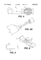
- FIG. 1 is a partial top view of a first preferred embodiment of a device embodying the present invention, which device includes an abrading element having a single abrading surface;
- FIG. 1A is a full top view of the device of FIG. 1 illustrating the handle of the device;
- FIG. 2 is a side view of the device shown in FIG. 1;
- FIG. 3 is an end view of the device shown in FIGS. 1 and 2;
- FIG. 4 is a second top view of the device shown in FIG. 1 and also illustrates the preferred range and type of motion of the abrading element;
- FIG. 4A is a partial view of the device of FIGS. 1-4 showing a preferred mechanism for connecting the handle to the device shaft;
- FIG. 5 is a detailed view of a portion of the device shaft illustrating notches used to hold a stop member in a selected position
- FIG. 6 is a detailed view of a spring-biased lever mechanism that may be used to adjust the position of a stop member
- FIG. 7 is a detailed view of a coupling mechanism that may be used to movably couple the drive mechanism to the abrading element;
- FIG. 8 is a detailed view of the mounting member disposed at the distal end of the device shaft
- FIG. 9 is a further detailed view of the coupling mechanism and mounting member illustrated in FIGS. 7 and 8;
- FIG. 10 is a detailed view illustrating a preferred way of movably connecting the coupling mechanism to the abrading element
- FIG. 11 is top view of a first vertebral body having a surface prepared in one of the end plates by a device incorporating the present invention
- FIG. 12 is a top view of a second vertebral body, different than that shown in FIG. 11, having a surface prepared in one of the end plates by a device incorporating the present invention
- FIG. 13 is a cutaway side view of the vertebral body shown in FIG. 12;
- FIG. 14 is a cutaway side view of adjacent vertebral bodies having their respective adjacent end plates prepared by a device incorporating the present invention to form a space configured to receive an insert;
- FIG. 15 is an exaggerated perspective view of the vertebral body illustrated in FIG. 12 showing the formation of the receiving surface in the vertebral end plate;
- FIG. 15A is a top view of a section of a human spine illustrating the portion of the disc that is typically removed to accommodate the implantation of an intervertebral insert;
- FIG. 16 is a top view of a second preferred embodiment of a device embodying the present invention, which device includes an abrading element having two abrading surfaces;
- FIG. 16A is a top view of the device of FIG. 16 illustrating irrigation and suction tubes that may be incorporated into the device;
- FIG. 17 is a side view of the device shown in FIG. 16;
- FIG. 17A is a side view of the device shown in FIG. 17;
- FIG. 17B is a detailed view of one possible drive mechanism that may be used with the second embodiment of the present invention.
- FIG. 18 is an alternative embodiment of an abrading element having two abrading surfaces, which abrading surfaces are inclined relative to one another to form a space between the adjacent vertebral bodies that approximates the lordotic curvature of a human spine at the location that will receive the interbody insert;
- FIG. 19 is a cutaway side view of adjacent vertebral bodies showing a lordotically configured space created between the vertebrae by the abrading element shown in FIG. 18;
- FIG. 20 shows an alternative embodiment of a mechanism for driving an abrading element
- FIG. 21 illustrates an alternative path of motion possible for an abrading element according to the present invention
- FIG. 22 illustrates a further alternative path of motion possible for the abrading element
- FIG. 23 illustrates an alternative configuration of the abrading element suitable for creating concave insert receiving surfaces on the adjacent vertebral end plates.
- the device in its preferred embodiment, generally comprises an abrading element movably and replaceably mounted on the distal end of a shaft, and a depth limiting mechanism to control the depth of insertion of the abrading element into the intervertebral space (i.e., the disc space).
- the device also includes a handle that may be detachable from the shaft.
- the term "handle” refers to a portion of the device that a surgeon may grip or otherwise manipulate to guide the working end of the device. That "handle” may, in fact, have multiple purposes.
- the handle may be a portion of the shaft on which the abrading element is mounted at one end.
- the handle may be part of a segment that connects the device to a power source, for example, part of a conduit that supplies pressurized gas if the power source is turbine driven.
- the term "handle” is used herein in its broadest context to refer to that portion of the device that the surgeon chooses to grasp.
- the shaft may be detachable from the abrading element.
- the device also includes a drive mechanism for transmitting power to activate, i.e., move, the abrading element, and the drive mechanism is connected to an energy source, e.g., a rechargeable battery, that may be housed within the handle of the device.
- the drive mechanism may comprise an electric motor or an electromagnetic oscillating mechanism.
- the drive mechanism and handle in which it is disposed may comprise the head unit of a gas powered turbine of the type commonly used in other surgical instruments.
- the abrading element is generally as wide as the insert to be implanted between the adjacent vertebral bodies adjacent the disc space.
- the receiving bed i.e., the prepared surface of the vertebrae, when formed by the device, will correspond in shape, size, and contour to the corresponding surfaces of the insert to be implanted.
- the surface produced may be flat or concave, or of some other desired shape and size so as to correspond to the upper or lower vertebrae contacting surfaces of the insert that will be implanted between the vertebrae.
- the device may also include a leading end that is capable of cutting through bone and/or disc material to form a pocket having a contour corresponding to the forward aspect and leading end of the insert to be implanted.
- the abrading element includes a single abrading surface that works on one vertebral surface at a time within the disc space.
- the abrading element includes a pair of opposed, outwardly facing abrading surfaces which lie in planes that may be either parallel to each other or, alternatively, convergent to each other.
- This embodiment of the present invention offers the further benefits of saving time by simultaneously preparing both of the vertebral end plates adjacent a disc space.
- the second embodiment not only includes the ability to simultaneously create two opposed surfaces, but also to shape the three-dimensional space that will be created between the adjacent vertebrae, which shape can be made to conform to the desired lordosis of that portion of the spine that will receive the insert.
- the abrading element of the present invention is not limited to being a unitary, one piece construction, regardless of the number of abrading surfaces the abrading element may have.
- the abrading element may comprise multiple pieces that, by way of example and not limitation, are mountable on the end of the device to, in combination, define the overall shape of the abrading element and its abrading surface or surfaces.
- the term "abrading element" is used herein to refer to both a unitary, one piece construction or a multi-piece construction.
- the present invention provides a device and method for preparing a disc space between adjacent vertebral bodies to receive an insert, and prepares that disc space by removing a portion of the end plate of the vertebrae adjacent that disc space to form predetermined surfaces in the end plates.
- the prepared surfaces are sized and contoured to have broad intimate contact with the insert to be implanted between the adjacent vertebrae, which broad contact provides for increased implant stability.
- This broad area of intimate contact between the vertebrae and the insert promotes bone ingrowth from the vertebrae into the insert, and also provides a broad area over which to support the incumbent loads so as to minimize the risk of vertebral collapse or subsidence of the insert into the vertebra.
- the abrading element is mounted on the mounting member and may be removable and interchangeable.
- the mounting member may be, but does not have to be, attachable to a shaft that is attachable to the handle.
- the abrading element and the mounting member may be separable from each other.
- the abrading element and the mounting member may, together, be removable from the handle.
- Various configurations of the abrading element and its abrading surface or surfaces can be used to form various contours in the adjacent vertebral bone structures.
- the opposite surface of the abrading element, or the opposite surface of the mounting member may be specifically designed to be non-abrading to the opposed adjacent vertebral end plate.
- a non-abrading surface may be designed to provide a mechanical advantage (such as achieved with a fulcrum) to allow the surgeon to increase the pressure of the abrading surface against the end plate being worked on, and, further, may be curved so as to be centering within the disc space by contact with a vertebral surface.
- an embodiment of the present invention may have upper and lower abrading surfaces that are in angular relationship to each other so as to, for example, match the natural lordotic curvature of the human spine at the location of the vertebrae to be operated upon.
- certain of the abrading surfaces of the abrading element may be configured with a convex, or even compound, geometry so as to form surfaces in the adjacent bone structures having a desired contour.
- sequentially larger ones of the abrading element, or mounting member may be used to form the desired space in a step-wise fashion, or the abrading element may be sized to substantially match the final desired width of the surface to be formed in the vertebral end plate.
- the abrading element may be configured with a sharpened leading edge to allow the abrading element to "forward cut" as it is inserted between the adjacent vertebrae. In this manner, progressive insertion of the abrading element between the vertebrae can be facilitated.
- a first embodiment of the present invention comprises a disc space preparation device generally referred to by numeral 10.
- Device 10 includes a shaft 12 and a handle 13.
- Handle 13 may be formed with any number of known shapes designed to make the surgeon's grip on the handle more secure or comfortable.
- handle 13 may include a soft rubber covering or may be formed, at least partially, of a material designed to promote a secure grip of the surgeon's hand on the handle.
- Those of ordinary skill in the art will recognize the many types of surface configurations or materials of which the handle can be made to achieve these goals.
- a drive mechanism diagrammatically depicted by box 14.
- the drive mechanism 14 is disposed within handle 13, it need not be disposed in the handle.
- the drive mechanism may be disposed completely or partially outside of the handle, for example, where the drive mechanism is a gas powered turbine element such as is used in some known surgical instruments.
- Drive mechanism 14 is operably connected to the proximal end of shaft 12 and is capable of moving an abrading element 18 disposed at a distal end 15 of shaft 12.
- Abrading element 18 has an abrading surface 19.
- Drive mechanism 14 moves abrading element 18 at a sufficiently high rate to quickly and efficiently cause abrading surface 19 to form the desired space and the desired surface contours in the adjacent vertebral bone structures.
- the abrading element 18 is mounted on a mounting member 16 disposed at the distal end 15 of shaft 12.
- the mounting member is fixed to shaft 12 and only the abrading element moves.
- many alternative mechanisms for mounting the abrading element on the device are possible within the scope of the present invention, including a mechanism wherein mounting member 16 is movably attached to shaft 12 and the drive mechanism moves both the mounting member and the abrading element attached thereto.
- mounting member 16 may be designed with a surface 17 on the side of the mounting member 16 opposite abrading element 18.
- Surface 17 is designed, in the embodiment shown, to bear against the end plate that is opposite the end plate being worked on by abrading element 18. In this manner, surface 17 provides a bearing surface that the surgeon may use to gain a mechanical advantage (such as with a lever) to contact abrading surface 19 of abrading element 18 against the end plate being worked on. Additionally, surface 17 may be curved as shown in FIG. 2, or otherwise shaped, to contact one end plate and, thereby, center or otherwise position abrading element 18 in the disc space.
- the motion of the abrading element may be vibratory, reciprocatory, oscillatory, or rotary.
- the motion of the abrading element is rotary in a clockwise then counterclockwise direction through a preferred range of motion of between 20° to 45°, as illustrated in FIG. 4.
- Whatever type and range of motion is selected for the abrading element, it will likely, although not necessarily, be in a direction that is generally parallel to the plane of the surface to be formed in the vertebral end plate.
- the shape of that surface contour is not necessarily flat, neither is the direction of the motion of the abrading element necessarily parallel to all points on that desired surface contour.
- the drive mechanism may comprise a magnetic driver of the type described in U.S. Pat. No. 5,263,218.
- the drive mechanism may take the form of a mechanical drive utilizing a cam mechanism such as described in U.S. Pat. No. 5,383,242.
- drive mechanisms used in known surgical power milling apparatus may also be used.
- the drive mechanism should be capable of moving the abrading element and its abrading surface or surfaces at a speed sufficient to abrade the hard cortical bone of the vertebral end plate. The working range and speed of motion of the drive mechanism will be readily selected by those of skill in the art.
- the stroke or amount of reciprocating movement is relatively small and can be selected as desired to achieve the purpose of abrading the adjacent bone structures. That stroke may be selected based on the relative strength of the bone structures to be abraded, the relative strength of the material forming the abrading element, and the type of surface roughening formed on one or more surfaces of the abrading element.
- This relatively small reciprocating movement of the abrading element results in a tightly controlled excursion area between the adjacent vertebrae being prepared to receive an insert.
- a motorized burr must be moved free hand and in a side-to-side motion within the disc space by the surgeon to form a space to receive an insert.
- motorized burr does not provide a way of forming a precise surface shape in the vertebral end plate. Additionally, because the motorized burr rotates in a single direction, it may catch on a piece of the vertebra and cause the burr to jerk forcefully out of the intervertebral space. Such an occurrence will not happen with the device 10 because of the controlled excursion of the device.
- drive mechanism 14 is powered by a rechargeable battery illustrated as box 66 in FIG. 1A.
- Battery 66 is also preferably located within handle 13 of device 10.
- the present invention is not limited to use with a rechargeable and/or replaceable battery 66, but may also be configured to run on any standard electrical source, such as 110 volt, 60 cycle power sources, with or without the accompanying use of a transformer to reduce that voltage as may be necessary and desirable.
- the drive mechanism may comprise a gas turbine mechanism as is common for many types of powered surgical instruments.
- the particular power source that powers drive mechanism 14 does not form a part of the present invention except to the extent it is adapted to achieve the appropriate and desirable amount of movement of the abrading element.
- mounting member 16 extends from the distal end 15 of shaft 12.
- the mounting member may be configured to house a portion of a coupling mechanism that, in turn, couples drive mechanism 14 to an abrading element 18 to move the abrading element in at least one degree of freedom while the mounting member remains stationary relative to the handle.
- degree of freedom is used herein in its ordinary sense to refer to motion in a standard three-dimensional environment. That three dimensional environment may be defined by X, Y, and Z axes.
- drive mechanism 14 is operable to move abrading element 18 in a reciprocating, oscillating, or vibrating motion transversely along one or more of the X, Y, and Z axes.
- drive mechanism 14 may be configured to move abrading element 18 around one or more of the X, Y, or Z axes.
- abrading element 18 includes a projection 20 (as best seen in FIG. 10) that is to be received in a corresponding aperture 21 formed in mounting member 16 (as best seen in FIG. 8).
- Mounting member 16 may be fixedly disposed on distal end 15 of shaft 12. Alternatively, mounting member 16 may be removably attached to distal end 15 of shaft 12.
- a coupling mechanism is used to couple abrading element 18 to mounting member 16 and to the drive mechanism.
- FIG. 10 illustrates that coupling mechanism with mounting member 16 removed to show in clearer detail the coupling mechanism.
- the coupling mechanism in the first preferred embodiment of the present invention comprises a generally tubular member 100 received within a hollow, longitudinal aperture of shaft 12.
- Tubular member 100 includes a proximal end 102 and a distal end 104.
- a T-shaped connector 108 is configured at the end of a drive rod 112.
- Drive rod 112 is adapted to be received within a corresponding aperture 110 in tubular member 100.
- a pivot rod 114 extends from the distal end 104 of tubular member 100 and is adapted to fit in a corresponding hole 115 formed in mounting member 16 at the end of shaft 12.
- mounting member 16 includes a central aperture 21 and an oblong slot 23 formed through a wall of mounting member 16. Slot 23 is configured to allow connector 108 to pass through when the connector is turned (as illustrated by the arrows in FIG. 7) so that the branches forming the "T" extend laterally.
- Mounting member 16 also includes a post 25 that projects into aperture 21. Post 25 is sized to mate with an aperture 27 formed in projection 20 of abrading element 18 as shown in FIG. 10. Projection 20 is also formed with a slot 29 designed to receive connector 108 as described below.
- tubular member 100 fits within shaft 12 with connector 108 extending from distal end 13 of the handle.
- Projection 20 of abrading element 18 is inserted into aperture 21 of mounting member 16 such that post 25 fits into aperture 27 of projection 20.
- Connector 108 is initially rotated such that its "T” branch fits through slot 23 of mounting member 16 and then is rotated 90° as shown by the arrows in FIG. 7. With the "T" branches of connector 108 extending parallel to post 25, projection 20 of abrading element 18 fits into aperture 21 of mounting member 16 such that connector 108 fits into slot 29, and post 25 fits into aperture 27.
- FIG. 10 shows the same structure as FIG. 9 but with mounting member 16 removed for purposes of better illustrating the mating of connector 108 with slot 29.
- pivot rod 114 fits into a mating aperture 115 formed at the distal end of shaft 12, and projection 20 includes a second slot 120 formed laterally from slot 29.
- Slot 120 is configured to allow connector 108 to toggle back and forth as tubular member 100 is reciprocatingly pivoted about pivot rod 114 by the device's drive mechanism. This "toggling" action of member 100 about pivot rod 114 moves T-shaped connector 108 and abrading element 18 in the direction indicated by the double headed arrow in FIG. 10.
- mounting element 16 may interchangeably receive various ones of abrading element 18.
- abrading element 18 may be quickly and easily attached to and detached from mounting member 16 during surgery.
- the abrading surface of the abrading element is selected to have a width that is substantially the same as the width of the surface to be formed in the vertebral end plate (to eliminate any need to move the abrading element side to side in the disc space as noted earlier)
- a surgeon might also elect to use an abrading element that is smaller in width than the ultimate desired width of the surface to be formed. Thereafter, the surgeon may use successively larger abrading elements 18 until she arrives at the desired dimensions of the space formed between the adjacent bone structures. This approach also eliminates any need to significantly move the abrading element in a side to side path within the disc space.
- device 10 includes at least one stop member 28 adjustably disposed on mounting element 16 to limit the travel of the abrading element into the adjacent bone structures.
- Stop member 28 includes an abutment 30 that will eventually contact the vertebrae to limit travel of the abrading element 18 as the abrading element forms the space between the adjacent vertebrae.
- Stop member 28 is not limited to a single abutment. Two or even more abutments may be formed around the circumference of stop member 28 and the leading edges of such multiple abutments may be configured to terminate at different positions relative to shaft 12. Other mechanisms for limiting the depth of insertion of the device into the disc space are possible, and this example is provided by way of illustration.
- stop member 28 In the embodiment of stop member 28 shown in FIGS. 1, 2, and 3, a slot 29 is formed in stop member 28 and an extension 31 projects from shaft 12 through slot 29. Slot 29 is dimensioned to correspond to the desired maximum amount of adjustment of the stop member relative to the handle.
- stop member 28 is held at a desired position on shaft 12 by spring-biased lever 32.
- Lever 32 includes an actuator end 33 with grooves, notches, knurls, or other surface preparation that is pushed toward shaft 12 against the bias of spring member 34 to lift engaging end 35 of lever 32 away from shaft 12.
- Engaging end 35 is configured to mate with notches 36 formed in shaft 12 as shown in FIG. 5. Notches 36 in shaft 12 are not visible in FIG.
- Step member 28 is also formed with an opening sized to allow engaging end 35 of lever 32 to fit in notches 36.
- spring biased lever 32 is provided in this embodiment of the present invention by way of example and not limitation.
- shaft 12 may include threads on a portion of its outer surface to receive a threaded adjusting collar that will lock stop member 28 in a desired position.
- FIGS. 21 and 22 examples of the types of motion through which abrading element 18 may be moved are illustrated.
- the motion is vibratory in a plane generally parallel to the abrading surface of the abrading element.
- the motion is linear and reciprocating as indicated by the double headed arrow of that figure.
- the motion may comprise slight rotation about a pivot point near distal end 15 of shaft 12 such that the oscillation is arcuate about an axis extending into and out of the sheet of paper on which FIGS. 21 and 22 are illustrated.
- Other motions such as full and complete rotation as described below with reference to the second preferred embodiment are also useful.
- abrading surface or surfaces of abrading element 18 will be adequate to cause the abrading surface or surfaces of abrading element 18 to abrade adjacent bone structures to thereby form the appropriately sized and dimensioned space between those bone structures for receiving an insert.
- at least one or more of the surfaces of abrading element 18 is roughened such that it can abrade the adjacent bone structures.
- FIGS. 11, 12, 13, 14, and 15 illustrate various views of vertebral bodies that have been worked on by a device incorporating the present invention.
- the cross-hatching in these figures represents the softer, blood rich cancellous bone of the vertebrae beneath the harder, outer cortical bone shell.
- FIG. 11 shows a top view of a first vertebral body 70 with a surface 72 formed by a circular abrading element 18 as shown in FIG. 1.
- the width of surface 72 formed on first vertebral body 72 closely matches the width of an abrading element 18 that was advanced into the disc space along a single front to back axis.
- a second vertebral body 77 has a greater depth than vertebral body 70.
- FIG. 12 has a surface 75 formed by extending abrading element 18 deeper into the distal interspace along front-to-back axis 74.
- FIG. 13 illustrates a cutaway side view of the vertebral body shown in top view in FIG. 12.
- FIG. 14 shows a cutaway side view of adjacent vertebral bodies 70 and 76 that have had surfaces 72 and 78 formed in their respective adjacent end plates. Note that, as shown in exaggerated view in FIG. 15, the vertebral end plate surface is prepared to a uniform shape, which while preserving the deeper portions of the end plate, also forms a socket depressed from the hard cortical uprisings of bone such as the uncovertebral joints 80. Recognize that the depth of this remaining end plate is exaggerated in FIG.
- This remaining portion of the more cortical rim 80 assists in retaining the insert in the desired position between the adjacent vertebrae by acting as an abutment preventing lateral or posteriad movement of the insert.
- the prepared faces of these abutment portions of the vertebral end plate also increase the surface area of contact between the insert and the vertebral body.
- FIG. 15A illustrates, in top view, the ideal portion of a disc that is removed to accommodate implantation of the insert.
- the annulus fibrosus is illustrated with rings 200 extending around the periphery of the intervertebral disc space.
- the nucleus pulposus 202 illustrated in cross-hatching.
- the general area and volume of the nucleus pulposus to be removed with the device of the present invention is illustrated with additional cross-hatchings 204.
- the preferred dimensions of the space created by the device is generally not as wide as the entire nucleus pulposus.
- abrading element 18 includes two abrading surfaces: an upper abrading surface 90 and a lower abrading surface 92.
- FIG. 16 is a top view of such a device and FIG. 17 is a side view.
- abrading element 18 includes two disc shaped members, 81 and 83, that are mounted on the distal and of the device by a recessed screw 147 and screw shaft 148 as described below.
- Abrading surface 90 is formed on one side of disc-shaped member 81
- abrading surface 92 is formed on one side of disc-shaped member 83.
- the present invention contemplates unitary, one piece constructions for the abrading element as well as multi-piece constructions.
- the upper and lower disc-shaped members 81 and 83 and their associated abrading surfaces may be rotated in opposite directions so as to counteract and balance any torque applied to the shaft and handle of the device as the abrading element digs into and abrades the vertebral end plates. This counter-rotation of the members 81 and 83 also prevents the device from being pulled to one side as the vertebral end plates are being worked on.
- This counter-rotating motion of the two members 81 and 83 is illustrated by the arrows in FIG. 17 and may be achieved, as illustrated in FIG. 17B, by using a spinning drive rod 160 that extends through shaft 12 and is configured with a gear 162 at its distal end that engages with mating gear teeth 93 and 94 formed on respective ones of disc-shaped members 81 and 83 as shown in FIGS. 17A and 17B.
- Disc shaped members 81 and 83 may be attached to the end of shaft 12 by a recessed screw 147 that is received in a mating, threaded screw shaft 148 as shown in FIG. 17B.
- the mounting member comprises threaded screw shaft 148 and recessed screw 147 disposed at the distal end of a tapered extension 149 that protrudes from shaft 12.
- FIGS. 16A and 17A show a further enhancement to the device shown in FIGS. 16 and 17 wherein the shaft 12 also includes an irrigation tube 150 and a suction tube 152 that may be formed within, or outside of, shaft 12. These irrigation and suction tubes may be connected to appropriate sources of irrigation fluid and a source of vacuum, respectively, to efficiently irrigate and clear the surgical site during use of the device.
- upper and lower disc-shaped members 94 and 96 may be formed with inwardly sloping, ramped surfaces 97 and 98 that engage a cone-shaped driver 99 disposed on the distal end of a rotating drive rod 160 to turn the upper and lower abrading surfaces in opposite directions as the drive rod spins about its axis.
- the lower surfaces of the abrading element 18 and the cone-shaped driver can be radially splined to engage one another.
- Such a dual surface abrading element can simultaneously work on both adjacent end plates of adjacent vertebrae.
- Abrading member 18 having such dual abrading surfaces can even be constructed such that the distance between the abrading surface is adjustable to accommodate variations in the height of the disc space.
- paired, wedge-shaped blocks may be disposed between the abrading surfaces and an adjusting screw can be provided to extend through threaded apertures in each wedge-shaped block. As the adjusting screw is turned, the wedge-shaped blocks move relative to one another to change the distance between the abrading surfaces.
- the abrading element 18 may have upper and lower abrading surfaces 140 and 142 that are angled or tilted relative to each other.
- the degree of angle or tilt may be selected to match the natural lordotic curvature of the spine at the location of the vertebrae to be worked on.
- the distance between the upper and lower abrading surfaces 140 and 142 in this embodiment may also be adjustable to accommodate differing disc heights between the vertebrae.
- Such angled abrading surfaces may also be driven in counter rotation by drive rod 160 as shown by the arrows in FIG. 18.
- the slope of the surfaces 144 and 146 formed in the adjacent vertebrae by the abrading element shown in FIG. 18 matches the lordotic curvature of the spine at that location.
- abrading elements 218 may be convex to form concave receiving surfaces 220 in the vertebral end plates.
- the geometry and configuration of the shapes of the abrading elements can be matched to the desired shape and configuration of the space which the surgeon intends to create between adjacent bone structures and to the desired contour of the surfaces created in the bone structures.
- abrading surface of abrading element 18 may be configured as roughenings, knurls, ridges, small pyramid shaped projections, or any other surface configuration that is capable of abrading the bone structures.
- an opposite surface may be configured to be supported by the adjacent end plate without causing any significant abrasion of that adjacent end plate.
- the non-abrading surface of the abrading element, or surface 17 of mounting member 16 may be configured to allow the surgeon to achieve a mechanical advantage that increases the bearing pressure of the abrading surface against the end plate being worked on, and also to locate and center the device. In this manner, one adjacent end plate provides mechanical support to the device while the device works on the adjacent end plate. After an appropriate surface is formed on one end plate, the device can be turned 180° to use the abrading surface on the other end plate.
- handle 12 of device 10 may be waterproof such that the device can be sterilized.
Priority Applications (17)
| Application Number | Priority Date | Filing Date | Title |
|---|---|---|---|
| US09/094,036 US6083228A (en) | 1998-06-09 | 1998-06-09 | Device and method for preparing a space between adjacent vertebrae to receive an insert |
| ES99928485T ES2267273T3 (es) | 1998-06-09 | 1999-06-09 | Dispositivo y metodo para la preparacion de un espacio entre vertebras adyacentes para recibir un elemento postizo. |
| DK99928485T DK1083829T3 (da) | 1998-06-09 | 1999-06-09 | Indretning til forberedelse af et rum mellem nabohvirvellegemer til optagelse af en indsats |
| JP2000552970A JP4083986B2 (ja) | 1998-06-09 | 1999-06-09 | 隣り合う椎体間に、インサートを受けるための空間を調製するための装置 |
| AT99928485T ATE328540T1 (de) | 1998-06-09 | 1999-06-09 | Gerät zur schaffung eines zwischenraumes zwischen benachbarten wirbeln für einen einschub |
| EP99928485A EP1083829B1 (fr) | 1998-06-09 | 1999-06-09 | Dispositif de preparation d'un espace entre des vertebres contigues destine a loger une piece rapportee |
| EP06113447A EP1681021A3 (fr) | 1998-06-09 | 1999-06-09 | Elément abrasif pour la préparation d'un espace entre vertèbres voisines |
| PCT/US1999/012890 WO1999063891A1 (fr) | 1998-06-09 | 1999-06-09 | Dispositif de preparation d'un espace entre des vertebres contigues destine a loger une piece rapportee |
| DE69931777T DE69931777T2 (de) | 1998-06-09 | 1999-06-09 | Gerät zur schaffung eines zwischenraumes zwischen benachbarten wirbeln für einen einschub |
| CA002334543A CA2334543C (fr) | 1998-06-09 | 1999-06-09 | Dispositif de preparation d'un espace entre des vertebres contigues destine a loger une piece rapportee |
| AU45542/99A AU760882B2 (en) | 1998-06-09 | 1999-06-09 | Device for preparing a space between adjacent vertebrae to receive an insert |
| US09/608,955 US6537279B1 (en) | 1998-06-09 | 2000-06-30 | Device and method for preparing a space between adjacent vertebrae to receive an insert |
| US09/663,311 US6517544B1 (en) | 1998-06-09 | 2000-09-15 | Device and method for preparing a space between adjacent vertebrae to receive an insert |
| US10/360,242 US6966912B2 (en) | 1998-06-09 | 2003-02-06 | Device and method for preparing a space between adjacent vertebrae to receive an insert |
| US10/396,093 US7160304B2 (en) | 1998-06-09 | 2003-03-25 | Method for preparing a space between adjacent vertebrae to receive an insert |
| US11/274,698 US8066707B2 (en) | 1998-06-09 | 2005-11-15 | Method for preparing a space in bone to receive an insert |
| US13/306,825 US8317794B2 (en) | 1998-06-09 | 2011-11-29 | Device for preparing a space in bone to receive an insert |
Applications Claiming Priority (2)
| Application Number | Priority Date | Filing Date | Title |
|---|---|---|---|
| US09/094,036 US6083228A (en) | 1998-06-09 | 1998-06-09 | Device and method for preparing a space between adjacent vertebrae to receive an insert |
| US09/608,955 US6537279B1 (en) | 1998-06-09 | 2000-06-30 | Device and method for preparing a space between adjacent vertebrae to receive an insert |
Related Child Applications (1)
| Application Number | Title | Priority Date | Filing Date |
|---|---|---|---|
| US09/608,955 Continuation US6537279B1 (en) | 1998-06-09 | 2000-06-30 | Device and method for preparing a space between adjacent vertebrae to receive an insert |
Publications (1)
| Publication Number | Publication Date |
|---|---|
| US6083228A true US6083228A (en) | 2000-07-04 |
Family
ID=22242425
Family Applications (3)
| Application Number | Title | Priority Date | Filing Date |
|---|---|---|---|
| US09/094,036 Expired - Lifetime US6083228A (en) | 1998-06-09 | 1998-06-09 | Device and method for preparing a space between adjacent vertebrae to receive an insert |
| US09/608,955 Expired - Lifetime US6537279B1 (en) | 1998-06-09 | 2000-06-30 | Device and method for preparing a space between adjacent vertebrae to receive an insert |
| US10/396,093 Expired - Lifetime US7160304B2 (en) | 1998-06-09 | 2003-03-25 | Method for preparing a space between adjacent vertebrae to receive an insert |
Family Applications After (2)
| Application Number | Title | Priority Date | Filing Date |
|---|---|---|---|
| US09/608,955 Expired - Lifetime US6537279B1 (en) | 1998-06-09 | 2000-06-30 | Device and method for preparing a space between adjacent vertebrae to receive an insert |
| US10/396,093 Expired - Lifetime US7160304B2 (en) | 1998-06-09 | 2003-03-25 | Method for preparing a space between adjacent vertebrae to receive an insert |
Country Status (10)
| Country | Link |
|---|---|
| US (3) | US6083228A (fr) |
| EP (1) | EP1083829B1 (fr) |
| JP (1) | JP4083986B2 (fr) |
| AT (1) | ATE328540T1 (fr) |
| AU (1) | AU760882B2 (fr) |
| CA (1) | CA2334543C (fr) |
| DE (1) | DE69931777T2 (fr) |
| DK (1) | DK1083829T3 (fr) |
| ES (1) | ES2267273T3 (fr) |
| WO (1) | WO1999063891A1 (fr) |
Cited By (152)
| Publication number | Priority date | Publication date | Assignee | Title |
|---|---|---|---|---|
| US20010010020A1 (en) * | 1999-03-05 | 2001-07-26 | Michelson Gary K. | Interbody spinal fusion implant having an anatomically conformed trailing end |
| US6391016B2 (en) * | 1998-05-01 | 2002-05-21 | Medtronic Xomed, Inc. | Methods for trephination and irrigation of the frontal sinus cavity |
| US20020116066A1 (en) * | 1996-09-13 | 2002-08-22 | Jean-Luc Chauvin | Expandable osteosynthesis cage |
| US6447512B1 (en) | 2000-01-06 | 2002-09-10 | Spinal Concepts, Inc. | Instrument and method for implanting an interbody fusion device |
| WO2002069811A1 (fr) * | 2001-03-02 | 2002-09-12 | Osteotech, Inc. | Extenseur vertebral |
| US6482209B1 (en) * | 2001-06-14 | 2002-11-19 | Gerard A. Engh | Apparatus and method for sculpting the surface of a joint |
| WO2003017853A1 (fr) | 2001-08-22 | 2003-03-06 | Sdgi Holdings, Inc. | Appareil d'usinage d'un tissu dur |
| US20030055503A1 (en) * | 2001-09-19 | 2003-03-20 | O'neil Michael J. | Alignment verification device and method of use |
| US6537279B1 (en) * | 1998-06-09 | 2003-03-25 | Gary K. Michelson | Device and method for preparing a space between adjacent vertebrae to receive an insert |
| US20030097134A1 (en) * | 2001-11-16 | 2003-05-22 | Sdgi Holdings, Inc. | Bone removal device and method of use |
| US20030130662A1 (en) * | 1998-06-09 | 2003-07-10 | Michelson Gary K. | Device and method for preparing a space between adjacent vertebrae to receive an insert |
| US20030135277A1 (en) * | 2001-11-26 | 2003-07-17 | Sdgi Holdings, Inc. | Implantable joint prosthesis and associated instrumentation |
| EP1346694A2 (fr) | 2002-03-19 | 2003-09-24 | DePuy AcroMed, Inc. | Dispositif de fraisage pour plateaux vertébraux |
| US20030199982A1 (en) * | 1998-09-04 | 2003-10-23 | Sdgi Holdings, Inc. | Peanut spectacle multi discoid thoraco-lumbar disc prosthesis |
| US20030199738A1 (en) * | 2000-08-08 | 2003-10-23 | Sdgi Holdings,Inc. | Clamping apparatus and methods |
| US20040002712A1 (en) * | 2002-06-26 | 2004-01-01 | Alexander Grinberg | Endplate shaping device |
| US20040010259A1 (en) * | 2002-03-12 | 2004-01-15 | Waldemar Link Gmbh & Co. | Cervical prosthesis and instrumentation therefor |
| US6692501B2 (en) * | 2000-12-14 | 2004-02-17 | Gary K. Michelson | Spinal interspace shaper |
| US20040054411A1 (en) * | 2000-08-08 | 2004-03-18 | Sdgi Holdings, Inc. | Wear-resistant endoprosthetic devices |
| US20040059337A1 (en) * | 2000-07-06 | 2004-03-25 | Sulzer Spine-Tech Inc. | Bone preparation instruments and methods |
| US20040073229A1 (en) * | 2002-10-11 | 2004-04-15 | Lin-Min Yang | Thoracic spine posterior transpedicular screw finder |
| US20040082958A1 (en) * | 2001-03-01 | 2004-04-29 | Michelson Gary K. | Dynamic guard and method for use thereof |
| US20040087957A1 (en) * | 2001-11-16 | 2004-05-06 | Sdgi Holdings, Inc. | Bone removal device and method of use |
| US20040093084A1 (en) * | 2001-02-04 | 2004-05-13 | Michelson Gary K. | Method for inserting and deploying an expandable interbody spinal fusion implant |
| US6736821B2 (en) | 2002-06-18 | 2004-05-18 | Sdgi Holdings, Inc. | System and method of mating implants and vertebral bodies |
| US20040098131A1 (en) * | 1996-07-22 | 2004-05-20 | Sdgi Holdings, Inc. | Human spinal disc prosthesis |
| US20040106927A1 (en) * | 2002-03-01 | 2004-06-03 | Ruffner Brian M. | Vertebral distractor |
| US6749636B2 (en) | 2001-04-02 | 2004-06-15 | Gary K. Michelson | Contoured spinal fusion implants made of bone or a bone composite material |
| US6755839B2 (en) | 2002-06-19 | 2004-06-29 | Sdgi Holdings, Inc. | Adjustable surgical guide and method of treating vertebral members |
| US6755841B2 (en) | 2000-05-08 | 2004-06-29 | Depuy Acromed, Inc. | Medical installation tool |
| US20040158254A1 (en) * | 2003-02-12 | 2004-08-12 | Sdgi Holdings, Inc. | Instrument and method for milling a path into bone |
| US20040177494A1 (en) * | 2002-03-12 | 2004-09-16 | Waldemar Link Gmbh & Co | Instrument set for fitting an intervertebral joint prosthesis |
| US20040199253A1 (en) * | 2003-04-07 | 2004-10-07 | Cervitech, Inc. | Cervical intervertebral disk prosthesis |
| WO2004089258A1 (fr) * | 2003-04-07 | 2004-10-21 | Cervitech, Inc. | Prothese articulaire intervertebrale pour la colonne cervicale |
| US20040215197A1 (en) * | 2003-04-24 | 2004-10-28 | Smith Maurice M. | Minimally invasive instruments and methods for preparing vertebral endplates |
| US20050015091A1 (en) * | 1997-10-06 | 2005-01-20 | Sdgi Holdings Inc. | Drill head for use in placing an intervertebral disc device |
| EP1514518A1 (fr) * | 2003-09-11 | 2005-03-16 | SDGI Holdings, Inc. | Instruments à percussion pour la préparation des plateaux vertébraux |
| US20050059976A1 (en) * | 2000-08-08 | 2005-03-17 | Sdgi Holdings, Inc. | Method and apparatus for stereotactic implantation |
| US20050065608A1 (en) * | 2000-02-04 | 2005-03-24 | Michelson Gary K. | Expandable threaded arcuate interbody spinal fusion implant with lordotic configuration during insertion |
| US6890355B2 (en) | 2001-04-02 | 2005-05-10 | Gary K. Michelson | Artificial contoured spinal fusion implants made of a material other than bone |
| US20050171550A1 (en) * | 2004-01-30 | 2005-08-04 | Sdgi Holdings, Inc. | Anatomic implants designed to minimize instruments and surgical techniques |
| US20050171605A1 (en) * | 2004-02-02 | 2005-08-04 | Cervitech, Inc. | Cervical prosthesis and instrument set |
| US20050197661A1 (en) * | 2004-03-03 | 2005-09-08 | Scimed Life Systems, Inc. | Tissue removal probe with sliding burr in cutting window |
| US20050203533A1 (en) * | 2004-03-12 | 2005-09-15 | Sdgi Holdings, Inc. | Technique and instrumentation for intervertebral prosthesis implantation |
| US20050203532A1 (en) * | 2004-03-12 | 2005-09-15 | Sdgi Holdings, Inc. | Technique and instrumentation for intervertebral prosthesis implantation using independent landmarks |
| US20050203527A1 (en) * | 2004-03-03 | 2005-09-15 | Scimed Life Systems, Inc. | Apparatus and methods for removing vertebral bone and disc tissue |
| US20050209622A1 (en) * | 2004-03-03 | 2005-09-22 | Scimed Life Systems, Inc. | Tissue removal probe with irrigation and aspiration ports |
| US20050216085A1 (en) * | 2001-02-04 | 2005-09-29 | Michelson Gary K | Method for using lordotic guard with moveable extensions for creating an implantation space posteriorly in the lumbar spine |
| US20050234455A1 (en) * | 2004-04-19 | 2005-10-20 | Lawrence Binder | Bone fixation plate |
| US20050273111A1 (en) * | 1999-10-08 | 2005-12-08 | Ferree Bret A | Methods and apparatus for intervertebral disc removal and endplate preparation |
| US6989031B2 (en) | 2001-04-02 | 2006-01-24 | Sdgi Holdings, Inc. | Hemi-interbody spinal implant manufactured from a major long bone ring or a bone composite |
| US20060020342A1 (en) * | 2004-07-21 | 2006-01-26 | Ferree Bret A | Facet-preserving artificial disc replacements |
| US20060024213A1 (en) * | 2004-07-28 | 2006-02-02 | Dainippon Screen Mfg. Co., Ltd. | Substrate treating apparatus |
| US20060025778A1 (en) * | 2004-07-21 | 2006-02-02 | Ferree Bret A | Methods and apparatus for artificial disc replacement (ADR) insertion and other surgical procedures |
| US20060030856A1 (en) * | 2004-07-21 | 2006-02-09 | Sdgi Holding, Inc. | Dual distractor inserter |
| US20060041313A1 (en) * | 2004-08-19 | 2006-02-23 | Sdgi Holdings, Inc. | Intervertebral disc system |
| US20060058585A1 (en) * | 2003-03-06 | 2006-03-16 | Martin Oberlaender | Medical instrument set and method for creating a surgical operating space in operations on the jaw |
| US20060074432A1 (en) * | 2004-10-06 | 2006-04-06 | Depuy Spine, Inc. | Modular medical tool and connector |
| US20060074425A1 (en) * | 2002-09-11 | 2006-04-06 | Chester Sutterlin | Systems and methods for removing body tissue |
| US20060089652A1 (en) * | 2004-10-26 | 2006-04-27 | Concept Matrix, Llc | Working channel for minimally invasive spine surgery |
| US20060095046A1 (en) * | 2004-11-01 | 2006-05-04 | Sdgi Holdings, Inc. | Devices and methods for explantation of intervertebral disc implants |
| US20060100634A1 (en) * | 2004-11-09 | 2006-05-11 | Sdgi Holdings, Inc. | Technique and instrumentation for measuring and preparing a vertebral body for device implantation using datum block |
| US20060135959A1 (en) * | 2004-03-22 | 2006-06-22 | Disc Dynamics, Inc. | Nuclectomy method and apparatus |
| US20060161189A1 (en) * | 2002-09-27 | 2006-07-20 | Harp Richard J | Surgical file system with a visualization instrument |
| US20060217731A1 (en) * | 2005-03-28 | 2006-09-28 | Sdgi Holdings, Inc. | X-ray and fluoroscopic visualization slots |
| US20060235418A1 (en) * | 2005-04-13 | 2006-10-19 | Sdgi Holdings, Inc. | Method and device for preparing a surface for receiving an implant |
| US20060247778A1 (en) * | 2005-01-26 | 2006-11-02 | Ferree Bret A | Intradiscal devices including spacers facilitating posterior-lateral and other insertion approaches |
| US20060253198A1 (en) * | 2005-05-03 | 2006-11-09 | Disc Dynamics, Inc. | Multi-lumen mold for intervertebral prosthesis and method of using same |
| US7153303B2 (en) | 2002-06-19 | 2006-12-26 | Sdgi Holdings, Inc. | Guide and blade for contouring vertebral bodies |
| US20070010822A1 (en) * | 2005-07-08 | 2007-01-11 | Edward Zalenski | Bone removal tool |
| US20070061011A1 (en) * | 2002-09-19 | 2007-03-15 | Spinalmotion, Inc. | Intervertebral Prosthesis |
| US20070123903A1 (en) * | 2005-10-31 | 2007-05-31 | Depuy Spine, Inc. | Medical Device installation tool and methods of use |
| US20070179615A1 (en) * | 2006-01-31 | 2007-08-02 | Sdgi Holdings, Inc. | Intervertebral prosthetic disc |
| US20070185375A1 (en) * | 2006-02-06 | 2007-08-09 | Depuy Spine, Inc. | Medical device installation tool |
| US20070208345A1 (en) * | 2003-04-28 | 2007-09-06 | Theirry Marnay | Instruments and method for preparing an intervertebral space for receiving an artificial disc implant |
| US20070213739A1 (en) * | 2001-03-01 | 2007-09-13 | Sdgi Holdings, Inc. | Method for using dynamic lordotic guard with movable extensions for creating an implantation space posteriorly in the lumbar spine |
| US20070233130A1 (en) * | 2006-03-28 | 2007-10-04 | Loubert Suddaby | Disk Preparation Tool |
| US20070235027A1 (en) * | 2004-11-10 | 2007-10-11 | Schuckmann Alfred V | Step-Action Indexing Mechanism |
| US20070270863A1 (en) * | 2006-04-20 | 2007-11-22 | Sdgi Holdings, Inc. | Devices and methods for contouring an intervertebral space between vertebral members |
| US20080125782A1 (en) * | 2006-11-29 | 2008-05-29 | Disc Dynamics, Inc. | Method and apparatus for removing an extension from a prosthesis |
| US20080140080A1 (en) * | 2006-12-12 | 2008-06-12 | Bernhard Strehl | Instrument to make openings in bone in the form of a bone lid |
| US20080234684A1 (en) * | 2007-02-08 | 2008-09-25 | Warsaw Orthopedic, Inc. | Instruments and techniques for guiding instruments to a spinal column |
| US20090030421A1 (en) * | 2007-07-23 | 2009-01-29 | Depuy Spine, Inc. | Implant engagement method and device |
| US20090076518A1 (en) * | 2004-03-22 | 2009-03-19 | Disc Dynamics, Inc. | Method and system for stabilizing adjacent vertebrae |
| US20090182341A1 (en) * | 2002-03-12 | 2009-07-16 | Cervitech, Inc. | Instrument set for fitting an intervertebral jont prosthesis |
| US20090199464A1 (en) * | 2008-02-12 | 2009-08-13 | Bp Corporation North America Inc. | Reduced RVP Oxygenated Gasoline Composition And Method |
| US20090209989A1 (en) * | 2008-02-13 | 2009-08-20 | U. S. Spinal Technologies, L.L.C. | Micro-Flail Assembly And Method Of Use For The Preparation Of A Nucleus/Vertebral End Cap Of A Spine |
| US20090222100A1 (en) * | 2008-02-28 | 2009-09-03 | Stryker Spine | Tool for implanting expandable intervertebral implant |
| US7585326B2 (en) | 2004-08-06 | 2009-09-08 | Spinalmotion, Inc. | Methods and apparatus for intervertebral disc prosthesis insertion |
| US20090277079A1 (en) * | 2008-05-08 | 2009-11-12 | Bp Corporation North America Inc. | Oxygenated gasoline composition having good driveability performance |
| WO2009143238A1 (fr) | 2008-05-22 | 2009-11-26 | Bp Corporation North America Inc. | Procédé de détermination des caractéristiques de distillation d'un produit pétrolier liquide contenant un mélange azéotrope |
| US20100087830A1 (en) * | 2008-10-03 | 2010-04-08 | Warsaw Orthopedic, Inc. | Endplate Preparation Instruments and Methods of Use |
| US7736380B2 (en) | 2004-12-21 | 2010-06-15 | Rhausler, Inc. | Cervical plate system |
| US7771475B2 (en) | 2002-02-02 | 2010-08-10 | Warsaw Orthopedic, Inc. | Spinal implant having deployable bone engaging projections |
| US20110023354A1 (en) * | 2005-01-25 | 2011-02-03 | Butamax(Tm) Advanced Biofuels Llc | Reduced rvp oxygenated gasoline composition and method |
| US20110071527A1 (en) * | 2009-09-24 | 2011-03-24 | Medicinelodge, Inc. Dba Imds Co-Innovation | Surgical rasping systems and mehtods |
| US20110137420A1 (en) * | 2000-02-04 | 2011-06-09 | Gary Karlin Michelson | Expandable push-in orthopedic implant |
| US8002834B2 (en) | 2004-07-30 | 2011-08-23 | Spinalmotion, Inc. | Intervertebral prosthetic disc with metallic core |
| US8021368B2 (en) * | 2004-01-14 | 2011-09-20 | Hudson Surgical Design, Inc. | Methods and apparatus for improved cutting tools for resection |
| US8080011B2 (en) | 2002-09-27 | 2011-12-20 | Surgitech, L.L.C. | Reciprocating cutting tool |
| WO2011159901A1 (fr) | 2010-06-16 | 2011-12-22 | Butamax(Tm) Advanced Biofuels Llc | Composition d'essence oxygénée à base de butanol offrant de bonnes performances de manipulation |
| WO2011159908A1 (fr) | 2010-06-16 | 2011-12-22 | Butamax(Tm) Advanced Biofuels Llc | Composition d'essence de butanol oxygéné permettant d'obtenir de bons résultats de conduite |
| US8083797B2 (en) | 2005-02-04 | 2011-12-27 | Spinalmotion, Inc. | Intervertebral prosthetic disc with shock absorption |
| US8090428B2 (en) | 2003-01-31 | 2012-01-03 | Spinalmotion, Inc. | Spinal midline indicator |
| US8092542B2 (en) | 2000-08-08 | 2012-01-10 | Warsaw Orthopedic, Inc. | Implantable joint prosthesis |
| US8092538B2 (en) | 2003-05-27 | 2012-01-10 | Spinalmotion, Inc. | Intervertebral prosthetic disc |
| US8100972B1 (en) | 2007-07-02 | 2012-01-24 | Theken Spine, Llc | Spinal cage having deployable member |
| US8114083B2 (en) | 2004-01-14 | 2012-02-14 | Hudson Surgical Design, Inc. | Methods and apparatus for improved drilling and milling tools for resection |
| US8206449B2 (en) | 2008-07-17 | 2012-06-26 | Spinalmotion, Inc. | Artificial intervertebral disc placement system |
| US8236034B2 (en) | 2004-04-19 | 2012-08-07 | Globus Medical, Inc. | Bone fixation plate |
| US8267997B2 (en) | 2007-11-12 | 2012-09-18 | Theken Spine, Llc | Vertebral interbody compression implant |
| US8287545B2 (en) | 2004-01-14 | 2012-10-16 | Hudson Surgical Design, Inc. | Methods and apparatus for enhanced retention of prosthetic implants |
| US8292957B2 (en) | 2000-04-19 | 2012-10-23 | Warsaw Orthopedic, Inc. | Bone hemi-lumbar arcuate interbody spinal fusion implant having an asymmetrical leading end |
| US8292958B1 (en) | 2007-07-02 | 2012-10-23 | Theken Spine, Llc | Spinal cage having deployable member |
| US8323340B2 (en) | 2000-04-19 | 2012-12-04 | Warsaw Orthopedic, Inc. | Artificial hemi-lumbar interbody spinal implant having an asymmetrical leading end |
| US8343220B2 (en) | 1999-05-05 | 2013-01-01 | Warsaw Orthopedic, Inc. | Nested interbody spinal fusion implants |
| US8366710B2 (en) | 2006-05-26 | 2013-02-05 | National University Corporation Nagoya University | External fixator |
| WO2013101256A2 (fr) | 2011-12-30 | 2013-07-04 | Butamax (Tm) Advanced Biofuels Llc | Compositions d'inhibiteurs de corrosion pour essences oxygénées |
| US8486147B2 (en) | 2006-04-12 | 2013-07-16 | Spinalmotion, Inc. | Posterior spinal device and method |
| US8506631B2 (en) | 2007-08-09 | 2013-08-13 | Spinalmotion, Inc. | Customized intervertebral prosthetic disc with shock absorption |
| US8545562B1 (en) | 2007-07-02 | 2013-10-01 | Theken Spine, Llc | Deployable member for use with an intervertebral cage |
| US8551098B2 (en) | 2010-08-17 | 2013-10-08 | Warsaw Orthopedic, Inc. | Bone scoring device |
| US8685035B2 (en) | 2003-01-31 | 2014-04-01 | Spinalmotion, Inc. | Intervertebral prosthesis placement instrument |
| US8740906B2 (en) | 2004-01-14 | 2014-06-03 | Hudson Surgical Design, Inc. | Method and apparatus for wireplasty bone resection |
| US8758441B2 (en) | 2007-10-22 | 2014-06-24 | Spinalmotion, Inc. | Vertebral body replacement and method for spanning a space formed upon removal of a vertebral body |
| US8764833B2 (en) | 2008-03-11 | 2014-07-01 | Spinalmotion, Inc. | Artificial intervertebral disc with lower height |
| US8845638B2 (en) | 2011-05-12 | 2014-09-30 | Nlt Spine Ltd. | Tissue disruption device and corresponding methods |
| US8845730B2 (en) | 2008-07-18 | 2014-09-30 | Simplify Medical, Inc. | Posterior prosthetic intervertebral disc |
| US8864829B1 (en) | 2007-07-02 | 2014-10-21 | Theken Spine, Llc | Spinal cage having deployable member |
| US9005203B2 (en) | 2009-09-24 | 2015-04-14 | Imds, Llc | Reciprocating surgical instruments |
| US9011544B2 (en) | 2008-05-05 | 2015-04-21 | Simplify Medical, Inc. | Polyaryletherketone artificial intervertebral disc |
| US9034038B2 (en) | 2008-04-11 | 2015-05-19 | Spinalmotion, Inc. | Motion limiting insert for an artificial intervertebral disc |
| US9033986B2 (en) | 2009-09-24 | 2015-05-19 | Imds, Llc | Reciprocating surgical instrument |
| US20150289888A1 (en) * | 2006-09-26 | 2015-10-15 | K2M, Inc. | Intervertebral prosthesis endplate having double dome and surgical tools for implanting same |
| US9198675B2 (en) | 2009-09-24 | 2015-12-01 | Imds Llc | Reciprocating surgical instrument |
| US9220603B2 (en) | 2008-07-02 | 2015-12-29 | Simplify Medical, Inc. | Limited motion prosthetic intervertebral disc |
| US9254139B2 (en) | 2006-07-31 | 2016-02-09 | DePuy Synthes Products, Inc. | Drilling/milling guide and keel cut preparation system |
| US9314348B2 (en) | 2014-06-04 | 2016-04-19 | Wenzel Spine, Inc. | Bilaterally expanding intervertebral body fusion device |
| US9320610B2 (en) | 2011-08-16 | 2016-04-26 | Stryker European Holdings I, Llc | Expandable implant |
| US9655741B2 (en) | 2003-05-27 | 2017-05-23 | Simplify Medical Pty Ltd | Prosthetic disc for intervertebral insertion |
| US20180303497A1 (en) * | 2016-04-28 | 2018-10-25 | David K. Boger | Oscillating decortication burr assembly |
| US10192038B2 (en) | 2008-05-22 | 2019-01-29 | Butamax Advanced Biofuels Llc | Process for determining the distillation characteristics of a liquid petroleum product containing an azeotropic mixture |
| US10342674B2 (en) | 2007-07-02 | 2019-07-09 | Theken Spine, Llc | Spinal cage having deployable member |
| US10342675B2 (en) | 2013-03-11 | 2019-07-09 | Stryker European Holdings I, Llc | Expandable implant |
| USD858769S1 (en) | 2014-11-20 | 2019-09-03 | Nuvasive, Inc. | Intervertebral implant |
| EP3607897A1 (fr) * | 2018-08-09 | 2020-02-12 | Wright Medical Technology, Inc. | Outil de retrait de cartilage |
| US10869689B2 (en) | 2017-05-03 | 2020-12-22 | Medtronic Vascular, Inc. | Tissue-removing catheter |
| US11219531B2 (en) | 2019-04-10 | 2022-01-11 | Wenzel Spine, Inc. | Rotatable intervertebral spacing implant |
| US11253371B2 (en) | 2019-12-27 | 2022-02-22 | Henry F. Fabian, JR. | Vertebral body shaver assembly |
| US11376017B2 (en) * | 2019-07-01 | 2022-07-05 | Fusion Orthopedics, Llc | Surgical instruments including a set of cutting burrs for performing an osteotomy |
| US11690645B2 (en) | 2017-05-03 | 2023-07-04 | Medtronic Vascular, Inc. | Tissue-removing catheter |
| US11819236B2 (en) | 2019-05-17 | 2023-11-21 | Medtronic Vascular, Inc. | Tissue-removing catheter |
Families Citing this family (91)
| Publication number | Priority date | Publication date | Assignee | Title |
|---|---|---|---|---|
| US6241729B1 (en) | 1998-04-09 | 2001-06-05 | Sdgi Holdings, Inc. | Method and instrumentation for posterior interbody fusion |
| JP4326134B2 (ja) | 1999-10-20 | 2009-09-02 | ウォーソー・オーソペディック・インコーポレーテッド | 外科的手順を実行する方法及び装置 |
| EP1263332B1 (fr) * | 2000-03-10 | 2016-04-27 | Smith & Nephew, Inc. | Appareil pour utilisation dans le cadre de l'arthroplastie des genoux |
| FR2811538B1 (fr) * | 2000-07-12 | 2003-02-07 | Spine Next Sa | Outil de curetage intervertebral |
| US6599291B1 (en) | 2000-10-20 | 2003-07-29 | Sdgi Holdings, Inc. | Methods and instruments for interbody surgical techniques |
| US6863859B2 (en) * | 2001-08-16 | 2005-03-08 | Objet Geometries Ltd. | Reverse thermal gels and the use thereof for rapid prototyping |
| US20080121343A1 (en) | 2003-12-31 | 2008-05-29 | Microfabrica Inc. | Electrochemical Fabrication Methods Incorporating Dielectric Materials and/or Using Dielectric Substrates |
| AU2003277287A1 (en) * | 2002-10-08 | 2004-05-04 | Warsaw Orthopedic, Inc. | Insertion device and techniques for orthopaedic implants |
| US20090076614A1 (en) * | 2007-09-17 | 2009-03-19 | Spinalmotion, Inc. | Intervertebral Prosthetic Disc with Shock Absorption Core |
| US7766914B2 (en) * | 2003-09-10 | 2010-08-03 | Warsaw Orthopedic, Inc. | Adjustable drill guide |
| US7625379B2 (en) * | 2004-01-26 | 2009-12-01 | Warsaw Orthopedic, Inc. | Methods and instrumentation for inserting intervertebral grafts and devices |
| US7862617B2 (en) * | 2004-07-27 | 2011-01-04 | Lamprich Medical, Llc | Spinal disc prosthesis apparatus and placement method |
| US7172628B2 (en) * | 2004-07-27 | 2007-02-06 | Lonnie Jay Lamprich | Spinal disc prosthesis and methods |
| US7776045B2 (en) * | 2004-08-20 | 2010-08-17 | Warsaw Orthopedic, Inc. | Instrumentation and methods for vertebral distraction |
| BRPI0515868A (pt) * | 2004-09-23 | 2008-08-12 | Spine Solutions Inc | implante, cinzel, conjunto de um implante, dispositivo para manter um espaço intervertebral aberto, ferramenta de montagem para montar um implante de um disco intervertebral, introdutor para inserir um implante, métodos para inserir um implante intervertebral, para determinar a posição e o tamanho ótimos de um implante intervertebral, para preparar um espaço intervertebral e para posicionar e fixar um implante intervertebral e usos de um implante, de um conjunto de implantes, de dois afastadores e de um batente ajustável |
| US7763024B2 (en) * | 2004-09-23 | 2010-07-27 | Spine Solutions, Inc. | Adjustable cutting of cutout in vertebral bone |
| EP1814474B1 (fr) | 2004-11-24 | 2011-09-14 | Samy Abdou | Dispositifs de placement d'un dispositif orthopedique intervertebral |
| US8523858B2 (en) * | 2005-06-21 | 2013-09-03 | DePuy Synthes Products, LLC | Adjustable fixation clamp and method |
| US20070179618A1 (en) * | 2006-01-31 | 2007-08-02 | Sdgi Holdings, Inc. | Intervertebral prosthetic disc |
| US8066714B2 (en) | 2006-03-17 | 2011-11-29 | Warsaw Orthopedic Inc. | Instrumentation for distraction and insertion of implants in a spinal disc space |
| AU2007276755A1 (en) | 2006-07-24 | 2008-01-31 | Spine Solutions, Inc. | Intervertebral implant with keel |
| KR100821698B1 (ko) | 2007-02-26 | 2008-04-14 | 주인탁 | 관절 연골 및 피질골 제거용 소형 전기톱 |
| ES2628055T3 (es) | 2007-07-27 | 2017-08-01 | R Tree Innovations, Llc | Sistema de implantación intercorporal |
| US8808380B2 (en) * | 2007-08-27 | 2014-08-19 | William Casey Fox | Method and apparatus for an osteotomy fixation or arthrodesis cage |
| US9017355B2 (en) | 2007-12-03 | 2015-04-28 | Covidien Ag | Battery-powered hand-held ultrasonic surgical cautery cutting device |
| US8419757B2 (en) | 2007-12-03 | 2013-04-16 | Covidien Ag | Cordless hand-held ultrasonic cautery cutting device |
| US9314261B2 (en) | 2007-12-03 | 2016-04-19 | Covidien Ag | Battery-powered hand-held ultrasonic surgical cautery cutting device |
| US8338726B2 (en) | 2009-08-26 | 2012-12-25 | Covidien Ag | Two-stage switch for cordless hand-held ultrasonic cautery cutting device |
| US8061014B2 (en) | 2007-12-03 | 2011-11-22 | Covidien Ag | Method of assembling a cordless hand-held ultrasonic cautery cutting device |
| US9005288B2 (en) | 2008-01-09 | 2015-04-14 | Providence Medical Techonlogy, Inc. | Methods and apparatus for accessing and treating the facet joint |
| WO2009094477A1 (fr) * | 2008-01-25 | 2009-07-30 | Spinalmotion, Inc. | Articulation prothétique implantable souple avec ressort préchargé |
| US9962166B1 (en) | 2008-02-12 | 2018-05-08 | David P. Sachs | Method and apparatus for performing a surgical operation on the cervical portion of the spine |
| US8262663B2 (en) * | 2008-05-05 | 2012-09-11 | Ranier Limited | Endplate preparation instrument |
| EP2328492B1 (fr) | 2008-06-06 | 2018-03-28 | Providence Medical Technology, Inc. | Implants pour articulation facettaire et outils de mise en place |
| US9814484B2 (en) | 2012-11-29 | 2017-11-14 | Microfabrica Inc. | Micro debrider devices and methods of tissue removal |
| US8795278B2 (en) | 2008-06-23 | 2014-08-05 | Microfabrica Inc. | Selective tissue removal tool for use in medical applications and methods for making and using |
| US9451977B2 (en) | 2008-06-23 | 2016-09-27 | Microfabrica Inc. | MEMS micro debrider devices and methods of tissue removal |
| US8414607B1 (en) | 2008-06-23 | 2013-04-09 | Microfabrica Inc. | Miniature shredding tool for use in medical applications and methods for making |
| US10939934B2 (en) | 2008-06-23 | 2021-03-09 | Microfabrica Inc. | Miniature shredding tools for use in medical applications, methods for making, and procedures for using |
| US8475458B2 (en) * | 2008-06-23 | 2013-07-02 | Microfabrica Inc. | Miniature shredding tool for use in medical applications and methods for making |
| US8808294B2 (en) | 2008-09-09 | 2014-08-19 | William Casey Fox | Method and apparatus for a multiple transition temperature implant |
| US10137000B1 (en) | 2008-12-05 | 2018-11-27 | Robert E Simonson | Method and apparatus for placement into iatrogenically created skeletal voids |
| US8323292B2 (en) * | 2008-12-15 | 2012-12-04 | Spinecore, Inc. | Adjustable pin drill guide and methods therefor |
| WO2010092893A1 (fr) * | 2009-02-10 | 2010-08-19 | 学校法人自治医科大学 | Système d'intervention chirurgicale pour fusion lombaire intervertébrale et dispositif pour maintenir l'espace intervertébral lombaire s'utilisant dans une intervention chirurgicale de fusion lombaire intervertébrale |
| JP5464892B2 (ja) | 2009-04-15 | 2014-04-09 | Ntn株式会社 | 遠隔操作型アクチュエータ |
| US8876828B2 (en) * | 2009-04-23 | 2014-11-04 | Ranier Limited | Vertebral surface preparation instrument |
| US8828082B2 (en) | 2009-07-09 | 2014-09-09 | R Tree Innovations, Llc | Inter-body implant |
| US20120191121A1 (en) | 2009-08-18 | 2012-07-26 | Chen Richard T | Concentric cutting devices for use in minimally invasive medical procedures |
| JP5599404B2 (ja) | 2009-09-29 | 2014-10-01 | テルモ株式会社 | 管腔閉塞物の除去機構を備えたカテーテル |
| US8764806B2 (en) | 2009-12-07 | 2014-07-01 | Samy Abdou | Devices and methods for minimally invasive spinal stabilization and instrumentation |
| US8465490B1 (en) | 2010-01-29 | 2013-06-18 | Greatbatch Ltd. | Disposable neucleotomy shaver |
| JP2012034883A (ja) * | 2010-08-09 | 2012-02-23 | Ntn Corp | 遠隔操作型アクチュエータ |
| CN103826556A (zh) * | 2011-07-28 | 2014-05-28 | 脊柱诊察公司 | 椎间盘切除装置和相关方法 |
| US8845728B1 (en) | 2011-09-23 | 2014-09-30 | Samy Abdou | Spinal fixation devices and methods of use |
| US20130226240A1 (en) | 2012-02-22 | 2013-08-29 | Samy Abdou | Spinous process fixation devices and methods of use |
| US11135026B2 (en) | 2012-05-11 | 2021-10-05 | Peter L. Bono | Robotic surgical system |
| US10194922B2 (en) | 2012-05-11 | 2019-02-05 | Peter L. Bono | Rotary oscillating bone, cartilage, and disk removal tool assembly |
| US9198767B2 (en) | 2012-08-28 | 2015-12-01 | Samy Abdou | Devices and methods for spinal stabilization and instrumentation |
| US9232953B2 (en) | 2012-10-08 | 2016-01-12 | Peter Bono | Cutting tool for bone, cartilage, and disk removal |
| US9320617B2 (en) | 2012-10-22 | 2016-04-26 | Cogent Spine, LLC | Devices and methods for spinal stabilization and instrumentation |
| EP3022064A4 (fr) | 2013-07-16 | 2017-06-07 | Microfabrica Inc. | Dispositifs, systèmes et procédés de lutte contre la contrefaçon et de sécurité |
| US9883887B2 (en) | 2013-07-25 | 2018-02-06 | Cardiovascular Systems, Inc. | Rotational atherectomy device with exchangeable drive shaft and meshing gears |
| US9724123B2 (en) | 2013-07-25 | 2017-08-08 | Cardiovascular Systems, Inc. | Rotational atherectomy device with exchangeable drive shaft and meshing gears |
| US9439674B2 (en) | 2013-07-25 | 2016-09-13 | Cardiovascular Systems, Inc. | Rotational atherectomy device with exchangeable drive shaft and meshing gears |
| US9750526B2 (en) | 2013-07-25 | 2017-09-05 | Cardiovascular Systems, Inc. | Rotational atherectomy device with exchangeable drive shaft and meshing gears |
| US9907566B2 (en) | 2013-07-25 | 2018-03-06 | Cardiovascualar Systems, Inc. | Rotational atherectomy device with exchangeable drive shaft and meshing gears |
| US9924964B2 (en) | 2013-07-25 | 2018-03-27 | Cardiovascular Systems, Inc. | Rotational atherectomy device with exchangeable drive shaft and meshing gears |
| DE102015112716A1 (de) * | 2015-07-23 | 2017-01-26 | Erchinger Medtechnology Gmbh & Co. Kg | Vorrichtung zum Abtrennen und Entfernen von Gewebeteilen |
| US10857003B1 (en) | 2015-10-14 | 2020-12-08 | Samy Abdou | Devices and methods for vertebral stabilization |
| CN105598797B (zh) * | 2016-02-19 | 2018-09-07 | 胡建坤 | 电动磨削器 |
| US10368898B2 (en) | 2016-05-05 | 2019-08-06 | Covidien Lp | Ultrasonic surgical instrument |
| US10973648B1 (en) | 2016-10-25 | 2021-04-13 | Samy Abdou | Devices and methods for vertebral bone realignment |
| US10744000B1 (en) | 2016-10-25 | 2020-08-18 | Samy Abdou | Devices and methods for vertebral bone realignment |
| AU2017361417A1 (en) | 2016-11-17 | 2019-06-13 | Capstone Surgical Technologies, Llc | Rotary oscillating surgical tool |
| EP3624708A1 (fr) | 2017-05-19 | 2020-03-25 | Providence Medical Technology, Inc. | Système de pose de fixation vertébrale et d'accès à celle-ci |
| CN111836589A (zh) | 2017-10-23 | 2020-10-27 | 彼得·L·波纳 | 旋转振荡和线性往复运动手术工具 |
| KR20190063541A (ko) | 2017-11-30 | 2019-06-10 | 주식회사 퍼스타 | 직업체험 교육용 실습 시스템 |
| WO2019136263A1 (fr) | 2018-01-04 | 2019-07-11 | Providence Medical Technology, Inc. | Vis à facettes et dispositif de pose |
| AU2019207913A1 (en) | 2018-01-12 | 2020-09-03 | Capstone Surgical Technologies, Llc | Robotic surgical control system |
| USD884172S1 (en) | 2018-01-12 | 2020-05-12 | Peter L. Bono | Surgical cutting tool |
| US11246617B2 (en) | 2018-01-29 | 2022-02-15 | Covidien Lp | Compact ultrasonic transducer and ultrasonic surgical instrument including the same |
| US11259832B2 (en) | 2018-01-29 | 2022-03-01 | Covidien Lp | Ultrasonic horn for an ultrasonic surgical instrument, ultrasonic surgical instrument including the same, and method of manufacturing an ultrasonic horn |
| US11246621B2 (en) | 2018-01-29 | 2022-02-15 | Covidien Lp | Ultrasonic transducers and ultrasonic surgical instruments including the same |
| US11229449B2 (en) | 2018-02-05 | 2022-01-25 | Covidien Lp | Ultrasonic horn, ultrasonic transducer assembly, and ultrasonic surgical instrument including the same |
| US10582944B2 (en) | 2018-02-23 | 2020-03-10 | Covidien Lp | Ultrasonic surgical instrument with torque assist feature |
| US10582933B2 (en) | 2018-03-22 | 2020-03-10 | Capstone Surgical Techologies, LLC | Oscillating surgical cutting tool |
| US11179248B2 (en) | 2018-10-02 | 2021-11-23 | Samy Abdou | Devices and methods for spinal implantation |
| EP3876860A1 (fr) | 2018-11-06 | 2021-09-15 | Bono, Peter L. | Système robotique chirurgical et procédé |
| CN110090062B (zh) * | 2019-05-31 | 2020-05-26 | 遵义医学院附属医院 | 一种可调型脊柱内镜下椎间盘的往复式切除装置 |
| US11857431B1 (en) | 2023-02-01 | 2024-01-02 | Robert E. Simonson | Method and apparatus for placement of vertebral body replacement device into a transcorporeal void during a surgical operation on the cervical portion of the spine |
| US11766338B1 (en) | 2023-02-06 | 2023-09-26 | Robert E. Simonson | Method and apparatus for placement of a reduced vertebral body replacement device during a surgical operation on the cervical portion of the spine including into a transcorporeal void |
Citations (6)
| Publication number | Priority date | Publication date | Assignee | Title |
|---|---|---|---|---|
| US3937222A (en) * | 1973-11-09 | 1976-02-10 | Surgical Design Corporation | Surgical instrument employing cutter means |
| US4842578A (en) * | 1986-03-12 | 1989-06-27 | Dyonics, Inc. | Surgical abrading instrument |
| US5387215A (en) * | 1992-02-12 | 1995-02-07 | Sierra Surgical Inc. | Surgical instrument for cutting hard tissue and method of use |
| US5601556A (en) * | 1994-03-18 | 1997-02-11 | Pisharodi; Madhavan | Apparatus for spondylolisthesis reduction |
| US5853415A (en) * | 1993-07-06 | 1998-12-29 | Zimmer, Inc. | Femoral milling instrumentation for use in total knee arthroplasty with optional cutting guide attachment |
| US5904687A (en) * | 1994-10-07 | 1999-05-18 | The Anspach Effort, Inc. | Tool holdling mechanism for a motor driven surgical instrument |
Family Cites Families (38)
| Publication number | Priority date | Publication date | Assignee | Title |
|---|---|---|---|---|
| US3384085A (en) * | 1964-07-03 | 1968-05-21 | Robert M. Hall | Surgical cutting tool |
| US3916907A (en) * | 1974-06-21 | 1975-11-04 | Wendell C Peterson | Spreader instrument for use in performing a spinal fusion |
| JPS59200644A (ja) * | 1983-04-27 | 1984-11-14 | オリンパス光学工業株式会社 | 外科用切除器具 |
| US4586497A (en) * | 1983-10-31 | 1986-05-06 | David J. Dapra | Drill fixation device and method for vertebra cutting |
| US4726806A (en) | 1984-08-14 | 1988-02-23 | Hiroshi Hukuba | Electric tooth-brush |
| US5484437A (en) * | 1988-06-13 | 1996-01-16 | Michelson; Gary K. | Apparatus and method of inserting spinal implants |
| US5015247A (en) * | 1988-06-13 | 1991-05-14 | Michelson Gary K | Threaded spinal implant |
| US5609635A (en) * | 1988-06-28 | 1997-03-11 | Michelson; Gary K. | Lordotic interbody spinal fusion implants |
| US5015255A (en) * | 1989-05-10 | 1991-05-14 | Spine-Tech, Inc. | Spinal stabilization method |
| US5269785A (en) * | 1990-06-28 | 1993-12-14 | Bonutti Peter M | Apparatus and method for tissue removal |
| US5189751A (en) | 1991-03-21 | 1993-03-02 | Gemtech, Inc. | Vibrating toothbrush using a magnetic driver |
| US5263218A (en) | 1991-03-21 | 1993-11-23 | Gemtech | Vibrating toothbrush using a magnetic driver |
| JP2500213B2 (ja) * | 1991-12-25 | 1996-05-29 | 住友ベークライト株式会社 | 外科手術用具 |
| US5383242A (en) | 1992-01-08 | 1995-01-24 | Bausch & Lomb Incorporated | Electric toothbrush |
| US5378153A (en) | 1992-02-07 | 1995-01-03 | Gemtech, Inc. | High performance acoustical cleaning apparatus for teeth |
| US5306309A (en) * | 1992-05-04 | 1994-04-26 | Calcitek, Inc. | Spinal disk implant and implantation kit |
| DE4225547A1 (de) | 1992-08-01 | 1994-02-03 | Bausch & Lomb | Elektrische Zahnbürste |
| US5305492A (en) | 1992-11-03 | 1994-04-26 | Optiva Corporation | Brush element for an acoustic toothbrush |
| US5435034A (en) | 1993-07-28 | 1995-07-25 | Bausch & Lomb Incorporated | Electric toothbrush |
| US5490860A (en) * | 1993-12-08 | 1996-02-13 | Sofamor Danek Properties, Inc. | Portable power cutting tool |
| FR2715293B1 (fr) | 1994-01-26 | 1996-03-22 | Biomat | Cage intersomatique vertébrale. |
| US5980522A (en) * | 1994-07-22 | 1999-11-09 | Koros; Tibor | Expandable spinal implants |
| FR2729557B1 (fr) * | 1995-01-24 | 1999-01-22 | Stryker Corp | Implant de type cage intersomatique, et instrumentation et procede pour sa pose |
| US5665122A (en) * | 1995-01-31 | 1997-09-09 | Kambin; Parviz | Expandable intervertebral cage and surgical method |
| US5591235A (en) * | 1995-03-15 | 1997-01-07 | Kuslich; Stephen D. | Spinal fixation device |
| ES2202580T3 (es) * | 1996-02-22 | 2004-04-01 | Sdgi Holdings, Inc. | Dispositivo de fusion intercorporal. |
| CA2199462C (fr) * | 1996-03-14 | 2006-01-03 | Charles J. Winslow | Methode et instruments pour proceder a l'insertion d'un implant |
| AU1078997A (en) * | 1996-04-12 | 1997-11-07 | Surgical Dynamics, Inc. | Surgical cutting device removably connected to a rotary drive element |
| US6159214A (en) | 1996-07-31 | 2000-12-12 | Michelson; Gary K. | Milling instrumentation and method for preparing a space between adjacent vertebral bodies |
| US5857995A (en) * | 1996-08-15 | 1999-01-12 | Surgical Dynamics, Inc. | Multiple bladed surgical cutting device removably connected to a rotary drive element |
| US6063088A (en) | 1997-03-24 | 2000-05-16 | United States Surgical Corporation | Method and instrumentation for implant insertion |
| US5865847A (en) * | 1997-03-06 | 1999-02-02 | Sulzer Spine-Tech Inc. | Lordotic spinal implant |
| US6241769B1 (en) * | 1998-05-06 | 2001-06-05 | Cortek, Inc. | Implant for spinal fusion |
| EP1681021A3 (fr) | 1998-06-09 | 2009-04-15 | Warsaw Orthopedic, Inc. | Elément abrasif pour la préparation d'un espace entre vertèbres voisines |
| US6083228A (en) * | 1998-06-09 | 2000-07-04 | Michelson; Gary K. | Device and method for preparing a space between adjacent vertebrae to receive an insert |
| AU2002213124B2 (en) * | 2000-10-11 | 2006-02-23 | Michael D. Mason | Graftless spinal fusion device |
| US6692501B2 (en) | 2000-12-14 | 2004-02-17 | Gary K. Michelson | Spinal interspace shaper |
| US6562045B2 (en) * | 2001-02-13 | 2003-05-13 | Sdgi Holdings, Inc. | Machining apparatus |
-
1998
- 1998-06-09 US US09/094,036 patent/US6083228A/en not_active Expired - Lifetime
-
1999
- 1999-06-09 DK DK99928485T patent/DK1083829T3/da active
- 1999-06-09 DE DE69931777T patent/DE69931777T2/de not_active Expired - Lifetime
- 1999-06-09 AU AU45542/99A patent/AU760882B2/en not_active Ceased
- 1999-06-09 AT AT99928485T patent/ATE328540T1/de not_active IP Right Cessation
- 1999-06-09 ES ES99928485T patent/ES2267273T3/es not_active Expired - Lifetime
- 1999-06-09 CA CA002334543A patent/CA2334543C/fr not_active Expired - Fee Related
- 1999-06-09 WO PCT/US1999/012890 patent/WO1999063891A1/fr active IP Right Grant
- 1999-06-09 EP EP99928485A patent/EP1083829B1/fr not_active Expired - Lifetime
- 1999-06-09 JP JP2000552970A patent/JP4083986B2/ja not_active Expired - Fee Related
-
2000
- 2000-06-30 US US09/608,955 patent/US6537279B1/en not_active Expired - Lifetime
-
2003
- 2003-03-25 US US10/396,093 patent/US7160304B2/en not_active Expired - Lifetime
Patent Citations (6)
| Publication number | Priority date | Publication date | Assignee | Title |
|---|---|---|---|---|
| US3937222A (en) * | 1973-11-09 | 1976-02-10 | Surgical Design Corporation | Surgical instrument employing cutter means |
| US4842578A (en) * | 1986-03-12 | 1989-06-27 | Dyonics, Inc. | Surgical abrading instrument |
| US5387215A (en) * | 1992-02-12 | 1995-02-07 | Sierra Surgical Inc. | Surgical instrument for cutting hard tissue and method of use |
| US5853415A (en) * | 1993-07-06 | 1998-12-29 | Zimmer, Inc. | Femoral milling instrumentation for use in total knee arthroplasty with optional cutting guide attachment |
| US5601556A (en) * | 1994-03-18 | 1997-02-11 | Pisharodi; Madhavan | Apparatus for spondylolisthesis reduction |
| US5904687A (en) * | 1994-10-07 | 1999-05-18 | The Anspach Effort, Inc. | Tool holdling mechanism for a motor driven surgical instrument |
Cited By (359)
| Publication number | Priority date | Publication date | Assignee | Title |
|---|---|---|---|---|
| USRE42576E1 (en) | 1994-11-14 | 2011-07-26 | Warsaw Orthopedic, Inc. | Human spinal disc prosthesis |
| USRE42480E1 (en) | 1994-11-14 | 2011-06-21 | Warsaw Orthopedic, Inc. | Human spinal disc prothesis with hinges |
| US20040098131A1 (en) * | 1996-07-22 | 2004-05-20 | Sdgi Holdings, Inc. | Human spinal disc prosthesis |
| US20110009972A1 (en) * | 1996-09-13 | 2011-01-13 | Jean-Luc Chauvin | Expandable osteosynthesis cage |
| US20020116066A1 (en) * | 1996-09-13 | 2002-08-22 | Jean-Luc Chauvin | Expandable osteosynthesis cage |
| US20060241774A1 (en) * | 1996-09-13 | 2006-10-26 | David Attali | Apparatus for providing proper vertebral spacing |
| US8435299B2 (en) | 1996-09-13 | 2013-05-07 | Wenzel Spine, Inc. | Expandable osteosynthesis cage |
| US8992621B2 (en) | 1996-09-13 | 2015-03-31 | Liliane Attali | Expandable osteosynthesis cage |
| US7828848B2 (en) | 1996-09-13 | 2010-11-09 | Wenzel Spine, Inc. | Expandable osteosynthesis cage |
| US8790407B2 (en) | 1996-09-13 | 2014-07-29 | Liliane Attali | Expandable osteosynthesis cage |
| US20050015091A1 (en) * | 1997-10-06 | 2005-01-20 | Sdgi Holdings Inc. | Drill head for use in placing an intervertebral disc device |
| US7331963B2 (en) | 1997-10-06 | 2008-02-19 | Warsaw Orthopedic, Inc. | Drill head for use in placing an intervertebral disc device |
| US6391017B2 (en) * | 1998-05-01 | 2002-05-21 | Medtronic Xomed, Inc. | Method for protecting soft tissue while drilling into underlying bone |
| US6391016B2 (en) * | 1998-05-01 | 2002-05-21 | Medtronic Xomed, Inc. | Methods for trephination and irrigation of the frontal sinus cavity |
| US20060100633A1 (en) * | 1998-06-09 | 2006-05-11 | Michelson Gary K | Method for preparing a space in bone to receive an insert |
| US8317794B2 (en) | 1998-06-09 | 2012-11-27 | Warsaw Orthopedic, Inc. | Device for preparing a space in bone to receive an insert |
| US7160304B2 (en) | 1998-06-09 | 2007-01-09 | Warsaw Orthopedic, Inc. | Method for preparing a space between adjacent vertebrae to receive an insert |
| US20030187448A1 (en) * | 1998-06-09 | 2003-10-02 | Michelson Gary K. | Method for preparing a space between adjacent vertebrae to receive an insert |
| US6966912B2 (en) | 1998-06-09 | 2005-11-22 | Sdgi Holdings, Inc. | Device and method for preparing a space between adjacent vertebrae to receive an insert |
| US8066707B2 (en) * | 1998-06-09 | 2011-11-29 | Warsaw Orthopedic, Inc. | Method for preparing a space in bone to receive an insert |
| US20030130662A1 (en) * | 1998-06-09 | 2003-07-10 | Michelson Gary K. | Device and method for preparing a space between adjacent vertebrae to receive an insert |
| US6537279B1 (en) * | 1998-06-09 | 2003-03-25 | Gary K. Michelson | Device and method for preparing a space between adjacent vertebrae to receive an insert |
| US20030199982A1 (en) * | 1998-09-04 | 2003-10-23 | Sdgi Holdings, Inc. | Peanut spectacle multi discoid thoraco-lumbar disc prosthesis |
| US20060074489A1 (en) * | 1998-09-04 | 2006-04-06 | Sdgi Holdings, Inc. | Peanut spectacle multi discoid thoraco-lumbar disc prosthesis |
| US8673004B2 (en) | 1999-03-05 | 2014-03-18 | Warsaw Orthopedic, Inc. | Method for inserting an interbody spinal fusion implant having an anatomically conformed trailing end |
| US20010010020A1 (en) * | 1999-03-05 | 2001-07-26 | Michelson Gary K. | Interbody spinal fusion implant having an anatomically conformed trailing end |
| US9078768B2 (en) | 1999-03-05 | 2015-07-14 | Warsaw Orthopedic, Inc. | Arcuate interbody spinal fusion implant having a reduced width and an anatomically conformed trailing end |
| US8882835B2 (en) | 1999-03-05 | 2014-11-11 | Warsaw Orthopedic, Inc. | Interbody spinal fusion implant having an anatomically conformed trailing end |
| US8343220B2 (en) | 1999-05-05 | 2013-01-01 | Warsaw Orthopedic, Inc. | Nested interbody spinal fusion implants |
| US20050273111A1 (en) * | 1999-10-08 | 2005-12-08 | Ferree Bret A | Methods and apparatus for intervertebral disc removal and endplate preparation |
| US6616671B2 (en) | 2000-01-06 | 2003-09-09 | Spinal Concepts, Inc. | Instrument and method for implanting an interbody fusion device |
| US6524312B2 (en) | 2000-01-06 | 2003-02-25 | Spinal Concepts, Inc. | Instrument and method for implanting an interbody fusion device |
| US6447512B1 (en) | 2000-01-06 | 2002-09-10 | Spinal Concepts, Inc. | Instrument and method for implanting an interbody fusion device |
| US20070032871A1 (en) * | 2000-02-04 | 2007-02-08 | Michelson Gary K | Expandable push-in arcuate orthopedic implant |
| US8771358B2 (en) | 2000-02-04 | 2014-07-08 | Warsaw Orthopedic, Inc. | Expandable push-in arcuate orthopedic implant |
| US20050065608A1 (en) * | 2000-02-04 | 2005-03-24 | Michelson Gary K. | Expandable threaded arcuate interbody spinal fusion implant with lordotic configuration during insertion |
| US20110137420A1 (en) * | 2000-02-04 | 2011-06-09 | Gary Karlin Michelson | Expandable push-in orthopedic implant |
| US8097034B2 (en) | 2000-02-04 | 2012-01-17 | Warsaw Orthopedic, Inc. | Expandable arcuate interbody spinal fusion implant with two expanders |
| US9345584B2 (en) | 2000-02-04 | 2016-05-24 | Warsaw Orthopedic, Inc. | Expandable push-in orthopedic implant |
| US8323340B2 (en) | 2000-04-19 | 2012-12-04 | Warsaw Orthopedic, Inc. | Artificial hemi-lumbar interbody spinal implant having an asymmetrical leading end |
| US8292957B2 (en) | 2000-04-19 | 2012-10-23 | Warsaw Orthopedic, Inc. | Bone hemi-lumbar arcuate interbody spinal fusion implant having an asymmetrical leading end |
| US8834569B2 (en) | 2000-04-19 | 2014-09-16 | Warsaw Orthopedic, Inc. | Artificial hemi-lumbar interbody spinal fusion cage having an asymmetrical leading end |
| USRE46410E1 (en) | 2000-05-08 | 2017-05-23 | DePuy Synthes Products, Inc. | Medical installation tool |
| USRE44835E1 (en) | 2000-05-08 | 2014-04-08 | Depuy Synthes Products Llc | Medical installation tool |
| US6755841B2 (en) | 2000-05-08 | 2004-06-29 | Depuy Acromed, Inc. | Medical installation tool |
| USRE45639E1 (en) | 2000-05-08 | 2015-08-04 | DePuy Synthes Products, Inc. | Medical installation tool |
| USRE43317E1 (en) | 2000-05-08 | 2012-04-17 | Depuy Spine, Inc. | Medical installation tool |
| US20040059337A1 (en) * | 2000-07-06 | 2004-03-25 | Sulzer Spine-Tech Inc. | Bone preparation instruments and methods |
| US20050059976A1 (en) * | 2000-08-08 | 2005-03-17 | Sdgi Holdings, Inc. | Method and apparatus for stereotactic implantation |
| US7179262B2 (en) * | 2000-08-08 | 2007-02-20 | Sdgi Holdings, Inc. | Method and apparatus for stereotactic implantation |
| US20040054411A1 (en) * | 2000-08-08 | 2004-03-18 | Sdgi Holdings, Inc. | Wear-resistant endoprosthetic devices |
| US20030199738A1 (en) * | 2000-08-08 | 2003-10-23 | Sdgi Holdings,Inc. | Clamping apparatus and methods |
| US8092542B2 (en) | 2000-08-08 | 2012-01-10 | Warsaw Orthopedic, Inc. | Implantable joint prosthesis |
| US8377063B2 (en) | 2000-12-14 | 2013-02-19 | Warsaw Orthopedic, Inc. | Method for preparing a space in the human spine |
| US7918855B2 (en) | 2000-12-14 | 2011-04-05 | Warsaw Orthopedic, Inc. | Spinal interspace shaper |
| US6692501B2 (en) * | 2000-12-14 | 2004-02-17 | Gary K. Michelson | Spinal interspace shaper |
| US20110172770A1 (en) * | 2000-12-14 | 2011-07-14 | Michelson Gary K | Method for preparing a space in the human spine |
| US7611514B2 (en) | 2000-12-14 | 2009-11-03 | Warsaw Orthopedic, Inc. | Spinal interspace shaper |
| US20100094299A1 (en) * | 2000-12-14 | 2010-04-15 | Michelson Gary K | Spinal interspace shaper |
| US20040162563A1 (en) * | 2000-12-14 | 2004-08-19 | Michelson Gary K. | Spinal interspace shaper |
| US8444692B2 (en) | 2001-02-04 | 2013-05-21 | Warsaw Orthopedic, Inc. | Instrumentation with inwardly moveable extensions for inserting an expandable interbody spinal fusion implant |
| US20050015149A1 (en) * | 2001-02-04 | 2005-01-20 | Michelson Gary K. | Instrumentation with inwardly moveable extensions for inserting an expandable interbody spinal fusion implant |
| US7922729B2 (en) * | 2001-02-04 | 2011-04-12 | Warsaw Orthopedic, Inc. | Instrumentation for inserting and deploying an expandable interbody spinal fusion implant |
| US8771321B2 (en) | 2001-02-04 | 2014-07-08 | Warsaw Orthopedic, Inc. | Method for loading a spinal implant |
| US20050216085A1 (en) * | 2001-02-04 | 2005-09-29 | Michelson Gary K | Method for using lordotic guard with moveable extensions for creating an implantation space posteriorly in the lumbar spine |
| US20050010294A1 (en) * | 2001-02-04 | 2005-01-13 | Michelson Gary K. | Instrumentation for inserting and deploying an expandable interbody spinal fusion implant |
| US7655027B2 (en) | 2001-02-04 | 2010-02-02 | Warsaw Orthopedic, Inc. | Method for inserting and deploying an expandable interbody spinal fusion implant |
| US20040093084A1 (en) * | 2001-02-04 | 2004-05-13 | Michelson Gary K. | Method for inserting and deploying an expandable interbody spinal fusion implant |
| US6562045B2 (en) * | 2001-02-13 | 2003-05-13 | Sdgi Holdings, Inc. | Machining apparatus |
| US7867238B2 (en) | 2001-03-01 | 2011-01-11 | Warsaw Orthopedic, Inc. | Method for using dynamic lordotic guard |
| US7998143B2 (en) | 2001-03-01 | 2011-08-16 | Warsaw Orthopedic, Inc. | Dynamic guard |
| US8764755B2 (en) | 2001-03-01 | 2014-07-01 | Warsaw Orthopedic, Inc. | Method for using a guard for creating a socket posteriorly in the lumbar spine |
| US9597202B2 (en) | 2001-03-01 | 2017-03-21 | Warsaw Orthopedic, Inc. | Method for using a guard for creating a socket posteriorly in the spine |
| US20040082958A1 (en) * | 2001-03-01 | 2004-04-29 | Michelson Gary K. | Dynamic guard and method for use thereof |
| US20070213739A1 (en) * | 2001-03-01 | 2007-09-13 | Sdgi Holdings, Inc. | Method for using dynamic lordotic guard with movable extensions for creating an implantation space posteriorly in the lumbar spine |
| US7955360B2 (en) | 2001-03-01 | 2011-06-07 | Warsaw Orthopedic, Inc. | Method for using dynamic lordotic guard with movable extensions for creating an implantation space posteriorly in the lumbar spine |
| US7909832B2 (en) | 2001-03-01 | 2011-03-22 | Warsaw Orthopedic, Inc. | Retractor for percutaneous surgery in a patient and method for use thereof |
| US8372079B2 (en) | 2001-03-01 | 2013-02-12 | Warsaw Orthopedic, Inc. | Dynamic guard and method for use thereof |
| US20070016220A1 (en) * | 2001-03-01 | 2007-01-18 | Sdgi Holding, Inc. | Method for using dynamic lordotic guard |
| US9211198B2 (en) | 2001-03-01 | 2015-12-15 | Warsaw Orthopedic, Inc. | Method for using a guard for creating a socket posteriorly in the lumbar spine |
| WO2002069811A1 (fr) * | 2001-03-02 | 2002-09-12 | Osteotech, Inc. | Extenseur vertebral |
| US7611536B2 (en) | 2001-04-02 | 2009-11-03 | Warsaw Orthopedic, Inc. | Hemi-interbody spinal fusion implants manufactured from a major long bone ring |
| US20040230308A1 (en) * | 2001-04-02 | 2004-11-18 | Michelson Gary K. | Contoured cortical bone implants |
| US7455692B2 (en) | 2001-04-02 | 2008-11-25 | Warsaw Orthopedic, Inc. | Hemi-artificial contoured spinal fusion implants made of a material other than bone |
| US20060122702A1 (en) * | 2001-04-02 | 2006-06-08 | Michelson Gary K | Hemi-interbody spinal fusion implants manufactured from a major long bone ring |
| US6749636B2 (en) | 2001-04-02 | 2004-06-15 | Gary K. Michelson | Contoured spinal fusion implants made of bone or a bone composite material |
| US7540882B2 (en) | 2001-04-02 | 2009-06-02 | Warsaw Orthopedic, Inc. | Artificial spinal fusion implant with asymmetrical leading end |
| US20050187629A1 (en) * | 2001-04-02 | 2005-08-25 | Michelson Gary K. | Hemi-artificial contoured spinal fusion implants made of a material other than bone |
| US7435262B2 (en) | 2001-04-02 | 2008-10-14 | Warsaw Orthopedic, Inc. | Contoured cortical bone implants |
| US20050187628A1 (en) * | 2001-04-02 | 2005-08-25 | Michelson Gary K. | Artificial spinal fusion implant with asymmetrical leading end |
| US6989031B2 (en) | 2001-04-02 | 2006-01-24 | Sdgi Holdings, Inc. | Hemi-interbody spinal implant manufactured from a major long bone ring or a bone composite |
| US8137403B2 (en) | 2001-04-02 | 2012-03-20 | Warsaw Orthopedic, Inc. | Hemi-interbody spinal fusion implants manufactured from a major long bone ring |
| US9463098B2 (en) | 2001-04-02 | 2016-10-11 | Warsaw Orthopedic, Inc. | Spinal fusion implant with bone screws and a bone screw lock |
| US8926703B2 (en) | 2001-04-02 | 2015-01-06 | Warsaw Orthopedic, Inc. | Spinal fusion implant with bone screws and a bone screw lock |
| US6890355B2 (en) | 2001-04-02 | 2005-05-10 | Gary K. Michelson | Artificial contoured spinal fusion implants made of a material other than bone |
| US7935149B2 (en) | 2001-04-02 | 2011-05-03 | Warsaw Orthopedic, Inc. | Spinal fusion implant with bone screws |
| US7896922B2 (en) | 2001-06-14 | 2011-03-01 | Alexandria Research Technologies, Llc | Implants for partial knee arthroplasty |
| US6482209B1 (en) * | 2001-06-14 | 2002-11-19 | Gerard A. Engh | Apparatus and method for sculpting the surface of a joint |
| WO2003017853A1 (fr) | 2001-08-22 | 2003-03-06 | Sdgi Holdings, Inc. | Appareil d'usinage d'un tissu dur |
| AU2002326694B2 (en) * | 2001-08-22 | 2007-07-05 | Warsaw Orthopedic, Inc. | Apparatus for machining hard tissue |
| US20030055503A1 (en) * | 2001-09-19 | 2003-03-20 | O'neil Michael J. | Alignment verification device and method of use |
| US20030097134A1 (en) * | 2001-11-16 | 2003-05-22 | Sdgi Holdings, Inc. | Bone removal device and method of use |
| US7294131B2 (en) * | 2001-11-16 | 2007-11-13 | Warsaw Orthopedic, Inc. | Bone removal device |
| US20040087957A1 (en) * | 2001-11-16 | 2004-05-06 | Sdgi Holdings, Inc. | Bone removal device and method of use |
| US20030135277A1 (en) * | 2001-11-26 | 2003-07-17 | Sdgi Holdings, Inc. | Implantable joint prosthesis and associated instrumentation |
| US20050096746A1 (en) * | 2001-11-26 | 2005-05-05 | Sdgi Holdings, Inc. | Instrumentation and associated methods for joint prosthesis implantation |
| US20100305702A1 (en) * | 2002-02-02 | 2010-12-02 | Michelson Gary K | Spinal implant having deployable bone engaging projections and method for installation thereof |
| US7771475B2 (en) | 2002-02-02 | 2010-08-10 | Warsaw Orthopedic, Inc. | Spinal implant having deployable bone engaging projections |
| US7972365B2 (en) | 2002-02-02 | 2011-07-05 | Warsaw Orthopedic, Inc. | Spinal implant having deployable bone engaging projections and method for installation thereof |
| US8845738B2 (en) | 2002-02-02 | 2014-09-30 | Warsaw Orthopedic, Inc. | Spinal implant having deployable bone engaging projections |
| US8579982B2 (en) | 2002-02-02 | 2013-11-12 | Warsaw Orthopedic, Inc. | Spinal implant having deployable bone engaging projections |
| US20110166655A1 (en) * | 2002-02-02 | 2011-07-07 | Michelson Gary K | Spinal implant having deployable bone engaging projections |
| US20040106927A1 (en) * | 2002-03-01 | 2004-06-03 | Ruffner Brian M. | Vertebral distractor |
| US20040177494A1 (en) * | 2002-03-12 | 2004-09-16 | Waldemar Link Gmbh & Co | Instrument set for fitting an intervertebral joint prosthesis |
| US20090182341A1 (en) * | 2002-03-12 | 2009-07-16 | Cervitech, Inc. | Instrument set for fitting an intervertebral jont prosthesis |
| US20040010259A1 (en) * | 2002-03-12 | 2004-01-15 | Waldemar Link Gmbh & Co. | Cervical prosthesis and instrumentation therefor |
| US7527629B2 (en) | 2002-03-12 | 2009-05-05 | Cervitech, Inc. | Instrument set for fitting an intervertebral joint prosthesis |
| EP1346694A3 (fr) * | 2002-03-19 | 2004-01-02 | DePuy AcroMed, Inc. | Dispositif de fraisage pour plateaux vertébraux |
| US6902568B2 (en) | 2002-03-19 | 2005-06-07 | Hassan Serhan | Vertebral endplate milling device |
| EP1346694A2 (fr) | 2002-03-19 | 2003-09-24 | DePuy AcroMed, Inc. | Dispositif de fraisage pour plateaux vertébraux |
| US6736821B2 (en) | 2002-06-18 | 2004-05-18 | Sdgi Holdings, Inc. | System and method of mating implants and vertebral bodies |
| US6755839B2 (en) | 2002-06-19 | 2004-06-29 | Sdgi Holdings, Inc. | Adjustable surgical guide and method of treating vertebral members |
| US7153303B2 (en) | 2002-06-19 | 2006-12-26 | Sdgi Holdings, Inc. | Guide and blade for contouring vertebral bodies |
| US20040002712A1 (en) * | 2002-06-26 | 2004-01-01 | Alexander Grinberg | Endplate shaping device |
| US7147642B2 (en) | 2002-06-26 | 2006-12-12 | Depuy Acromed, Inc. | Endplate shaping device |
| US20100234848A1 (en) * | 2002-09-11 | 2010-09-16 | Chester Sutterlin | Systems and Methods for Removing Body Tissue |
| US20060074425A1 (en) * | 2002-09-11 | 2006-04-06 | Chester Sutterlin | Systems and methods for removing body tissue |
| US7722613B2 (en) | 2002-09-11 | 2010-05-25 | Nuvasive, Inc. | Systems and methods for removing body tissue |
| US10166113B2 (en) | 2002-09-19 | 2019-01-01 | Simplify Medical Pty Ltd | Intervertebral prosthesis |
| US11707360B2 (en) | 2002-09-19 | 2023-07-25 | Simplify Medical Pty Ltd | Intervertebral prosthesis |
| US11285013B2 (en) | 2002-09-19 | 2022-03-29 | Simplify Medical Pty Ltd | Intervertebral prosthesis |
| US20070061011A1 (en) * | 2002-09-19 | 2007-03-15 | Spinalmotion, Inc. | Intervertebral Prosthesis |
| US9839525B2 (en) | 2002-09-19 | 2017-12-12 | Simplify Medical Pty Ltd | Intervertebral prosthesis |
| US8262732B2 (en) | 2002-09-19 | 2012-09-11 | Spinalmotion, Inc. | Intervertebral prosthesis |
| US20080228277A1 (en) * | 2002-09-19 | 2008-09-18 | Spinalmotion, Inc. | Intervertebral prosthesis |
| US10517738B2 (en) | 2002-09-19 | 2019-12-31 | Simplify Medical Pty Ltd | Intervertebral prothesis |
| US7731754B2 (en) | 2002-09-19 | 2010-06-08 | Spinalmotion, Inc. | Intervertebral prosthesis |
| US11344427B2 (en) | 2002-09-19 | 2022-05-31 | Simplify Medical Pty Ltd | Intervertebral prosthesis |
| US10413420B2 (en) | 2002-09-19 | 2019-09-17 | Simplify Medical Pty Ltd | Intervertebral prosthesis |
| US8100823B2 (en) | 2002-09-27 | 2012-01-24 | Surgitech, Llc | Surgical file system with a visualization instrument |
| US20060161189A1 (en) * | 2002-09-27 | 2006-07-20 | Harp Richard J | Surgical file system with a visualization instrument |
| US8080011B2 (en) | 2002-09-27 | 2011-12-20 | Surgitech, L.L.C. | Reciprocating cutting tool |
| US20040073229A1 (en) * | 2002-10-11 | 2004-04-15 | Lin-Min Yang | Thoracic spine posterior transpedicular screw finder |
| US8090428B2 (en) | 2003-01-31 | 2012-01-03 | Spinalmotion, Inc. | Spinal midline indicator |
| US8685035B2 (en) | 2003-01-31 | 2014-04-01 | Spinalmotion, Inc. | Intervertebral prosthesis placement instrument |
| US10105131B2 (en) | 2003-01-31 | 2018-10-23 | Simplify Medical Pty Ltd | Intervertebral prosthesis placement instrument |
| US9402745B2 (en) | 2003-01-31 | 2016-08-02 | Simplify Medical, Inc. | Intervertebral prosthesis placement instrument |
| WO2004071282A2 (fr) * | 2003-02-12 | 2004-08-26 | Sdgi Holdings, Inc. | Instrument et methode de fraisage d'une voie dans un os |
| WO2004071282A3 (fr) * | 2003-02-12 | 2005-03-24 | Sdgi Holdings Inc | Instrument et methode de fraisage d'une voie dans un os |
| US20040158254A1 (en) * | 2003-02-12 | 2004-08-12 | Sdgi Holdings, Inc. | Instrument and method for milling a path into bone |
| US20060058585A1 (en) * | 2003-03-06 | 2006-03-16 | Martin Oberlaender | Medical instrument set and method for creating a surgical operating space in operations on the jaw |
| US20040199253A1 (en) * | 2003-04-07 | 2004-10-07 | Cervitech, Inc. | Cervical intervertebral disk prosthesis |
| US20060195189A1 (en) * | 2003-04-07 | 2006-08-31 | Cervitech, Inc. | Prosthetic joint of cervical intervertebral for a cervical spine |
| US20060100708A1 (en) * | 2003-04-07 | 2006-05-11 | Cervitech, Inc. | Method for implanting cervical intervertebral disk prosthesis |
| US8147551B2 (en) | 2003-04-07 | 2012-04-03 | Cervitech, Inc. | Method for implanting an intervertebral disk prosthesis |
| US8012212B2 (en) | 2003-04-07 | 2011-09-06 | Nuvasive, Inc. | Cervical intervertebral disk prosthesis |
| JP2006521845A (ja) * | 2003-04-07 | 2006-09-28 | サービテック・インコーポレイテッド | 頚椎のための椎間関節人工装具 |
| WO2004089258A1 (fr) * | 2003-04-07 | 2004-10-21 | Cervitech, Inc. | Prothese articulaire intervertebrale pour la colonne cervicale |
| US8591586B2 (en) * | 2003-04-07 | 2013-11-26 | Cervitech, Inc. | Cervical intervertebral prosthesis |
| US20120191198A1 (en) * | 2003-04-07 | 2012-07-26 | Link Helmut D | Cervical intervertebral prostehsis |
| US20040215197A1 (en) * | 2003-04-24 | 2004-10-28 | Smith Maurice M. | Minimally invasive instruments and methods for preparing vertebral endplates |
| US20100152791A1 (en) * | 2003-04-24 | 2010-06-17 | Smith Maurice M | Minimally invasive instruments and methods for preparing vertebral endplates |
| US7674265B2 (en) * | 2003-04-24 | 2010-03-09 | Warsaw Orthopedic, Inc. | Minimally invasive instruments and methods for preparing vertebral endplates |
| US8460296B2 (en) | 2003-04-24 | 2013-06-11 | Warsaw Orthopedic, Inc. | Minimally invasive instruments and methods for preparing vertebral endplates |
| US10182831B2 (en) | 2003-04-28 | 2019-01-22 | Centinel Spine Llc | Instruments and method for preparing an intervertebral space for receiving an artificial disc implant |
| US8663229B2 (en) | 2003-04-28 | 2014-03-04 | DePuy Synthes Products, LLC | Instruments and method for preparing an intervertebral space for receiving an artificial disc implant |
| US8419742B2 (en) * | 2003-04-28 | 2013-04-16 | Spine Solutions, Inc. | Instruments and method for preparing an intervertebral space for receiving an artificial disc implant |
| US20070208345A1 (en) * | 2003-04-28 | 2007-09-06 | Theirry Marnay | Instruments and method for preparing an intervertebral space for receiving an artificial disc implant |
| USRE46802E1 (en) | 2003-05-27 | 2018-04-24 | Simplify Medical Pty Limited | Intervertebral prosthetic disc with metallic core |
| US10357376B2 (en) | 2003-05-27 | 2019-07-23 | Simplify Medical Pty Ltd | Intervertebral prosthetic disc |
| US11771565B2 (en) | 2003-05-27 | 2023-10-03 | Simplify Medical Pty Ltd | Prosthetic disc for intervertebral insertion |
| US9788965B2 (en) | 2003-05-27 | 2017-10-17 | Simplify Medical Pty Ltd | Prosthetic disc for intervertebral insertion |
| US11376130B2 (en) | 2003-05-27 | 2022-07-05 | Simplify Medical Pty Ltd | Intervertebral prosthetic disc |
| US10342671B2 (en) | 2003-05-27 | 2019-07-09 | Simplify Medical Pty Ltd | Intervertebral prosthetic disc |
| US9655741B2 (en) | 2003-05-27 | 2017-05-23 | Simplify Medical Pty Ltd | Prosthetic disc for intervertebral insertion |
| US8771356B2 (en) | 2003-05-27 | 2014-07-08 | Spinalmotion, Inc. | Intervertebral prosthetic disc |
| US8454698B2 (en) | 2003-05-27 | 2013-06-04 | Spinalmotion, Inc. | Prosthetic disc for intervertebral insertion |
| US8444695B2 (en) | 2003-05-27 | 2013-05-21 | Spinalmotion, Inc. | Prosthetic disc for intervertebral insertion |
| US10219911B2 (en) | 2003-05-27 | 2019-03-05 | Simplify Medical Pty Ltd | Prosthetic disc for intervertebral insertion |
| US8845729B2 (en) | 2003-05-27 | 2014-09-30 | Simplify Medical, Inc. | Prosthetic disc for intervertebral insertion |
| US9107762B2 (en) | 2003-05-27 | 2015-08-18 | Spinalmotion, Inc. | Intervertebral prosthetic disc with metallic core |
| US9439774B2 (en) | 2003-05-27 | 2016-09-13 | Simplify Medical Pty Ltd | Intervertebral prosthetic disc |
| US10342670B2 (en) | 2003-05-27 | 2019-07-09 | Simplify Medical Pty Ltd | Intervertebral prosthetic disc |
| US8092538B2 (en) | 2003-05-27 | 2012-01-10 | Spinalmotion, Inc. | Intervertebral prosthetic disc |
| US8974533B2 (en) | 2003-05-27 | 2015-03-10 | Simplify Medical, Inc. | Prosthetic disc for intervertebral insertion |
| US10052211B2 (en) | 2003-05-27 | 2018-08-21 | Simplify Medical Pty Ltd. | Prosthetic disc for intervertebral insertion |
| EP1514518A1 (fr) * | 2003-09-11 | 2005-03-16 | SDGI Holdings, Inc. | Instruments à percussion pour la préparation des plateaux vertébraux |
| US20090270871A1 (en) * | 2003-09-11 | 2009-10-29 | Mingyan Liu | Impulsive percussion instruments for endplate preparation |
| US20050065529A1 (en) * | 2003-09-11 | 2005-03-24 | Mingyan Liu | Impulsive percussion instruments for endplate preparation |
| US7569057B2 (en) | 2003-09-11 | 2009-08-04 | Warsaw Orthopedic, Inc. | Impulsive percussion instruments for endplate preparation |
| US8021368B2 (en) * | 2004-01-14 | 2011-09-20 | Hudson Surgical Design, Inc. | Methods and apparatus for improved cutting tools for resection |
| US9814539B2 (en) | 2004-01-14 | 2017-11-14 | Puget Bioventures Llc | Methods and apparatus for conformable prosthetic implants |
| US8287545B2 (en) | 2004-01-14 | 2012-10-16 | Hudson Surgical Design, Inc. | Methods and apparatus for enhanced retention of prosthetic implants |
| US8114083B2 (en) | 2004-01-14 | 2012-02-14 | Hudson Surgical Design, Inc. | Methods and apparatus for improved drilling and milling tools for resection |
| US8740906B2 (en) | 2004-01-14 | 2014-06-03 | Hudson Surgical Design, Inc. | Method and apparatus for wireplasty bone resection |
| US7645281B2 (en) | 2004-01-30 | 2010-01-12 | Warsaw Orthopedic, Inc. | Anatomic implants designed to minimize instruments and surgical techniques |
| US20050171550A1 (en) * | 2004-01-30 | 2005-08-04 | Sdgi Holdings, Inc. | Anatomic implants designed to minimize instruments and surgical techniques |
| US20080051907A1 (en) * | 2004-01-30 | 2008-02-28 | Warsaw Orthopedic, Inc. | Anatomic Implants Designed to Minimize Instruments and Surgical Techniques |
| US20050171605A1 (en) * | 2004-02-02 | 2005-08-04 | Cervitech, Inc. | Cervical prosthesis and instrument set |
| US20080033555A1 (en) * | 2004-02-02 | 2008-02-07 | Cervitech, Inc. | Cervical prosthesis and instrument set |
| US8353914B2 (en) | 2004-02-02 | 2013-01-15 | Hudson Surgical Design, Inc. | Methods and apparatus for improved profile based resection |
| US9474536B2 (en) | 2004-03-03 | 2016-10-25 | Boston Scientific Scimed, Inc. | Apparatus and methods for removing vertebral bone and disc tissue |
| US8784421B2 (en) | 2004-03-03 | 2014-07-22 | Boston Scientific Scimed, Inc. | Apparatus and methods for removing vertebral bone and disc tissue |
| US20050203527A1 (en) * | 2004-03-03 | 2005-09-15 | Scimed Life Systems, Inc. | Apparatus and methods for removing vertebral bone and disc tissue |
| US20050209622A1 (en) * | 2004-03-03 | 2005-09-22 | Scimed Life Systems, Inc. | Tissue removal probe with irrigation and aspiration ports |
| US20050197661A1 (en) * | 2004-03-03 | 2005-09-08 | Scimed Life Systems, Inc. | Tissue removal probe with sliding burr in cutting window |
| US20050203532A1 (en) * | 2004-03-12 | 2005-09-15 | Sdgi Holdings, Inc. | Technique and instrumentation for intervertebral prosthesis implantation using independent landmarks |
| US20050203533A1 (en) * | 2004-03-12 | 2005-09-15 | Sdgi Holdings, Inc. | Technique and instrumentation for intervertebral prosthesis implantation |
| US20060135959A1 (en) * | 2004-03-22 | 2006-06-22 | Disc Dynamics, Inc. | Nuclectomy method and apparatus |
| US20090076518A1 (en) * | 2004-03-22 | 2009-03-19 | Disc Dynamics, Inc. | Method and system for stabilizing adjacent vertebrae |
| US8236034B2 (en) | 2004-04-19 | 2012-08-07 | Globus Medical, Inc. | Bone fixation plate |
| US7963981B2 (en) | 2004-04-19 | 2011-06-21 | Globus Medical, Inc. | Bone fixation plate |
| US20050234455A1 (en) * | 2004-04-19 | 2005-10-20 | Lawrence Binder | Bone fixation plate |
| US9364272B2 (en) | 2004-04-19 | 2016-06-14 | Globus Medical, Inc. | Bone fixation plate |
| US20060020342A1 (en) * | 2004-07-21 | 2006-01-26 | Ferree Bret A | Facet-preserving artificial disc replacements |
| US20060030856A1 (en) * | 2004-07-21 | 2006-02-09 | Sdgi Holding, Inc. | Dual distractor inserter |
| US20060025778A1 (en) * | 2004-07-21 | 2006-02-02 | Ferree Bret A | Methods and apparatus for artificial disc replacement (ADR) insertion and other surgical procedures |
| US7625380B2 (en) | 2004-07-21 | 2009-12-01 | Warsaw Orthopedic, Inc. | Dual distractor inserter |
| US20060024213A1 (en) * | 2004-07-28 | 2006-02-02 | Dainippon Screen Mfg. Co., Ltd. | Substrate treating apparatus |
| US8002834B2 (en) | 2004-07-30 | 2011-08-23 | Spinalmotion, Inc. | Intervertebral prosthetic disc with metallic core |
| US8062371B2 (en) | 2004-07-30 | 2011-11-22 | Spinalmotion, Inc. | Intervertebral prosthetic disc with metallic core |
| US10085853B2 (en) | 2004-08-06 | 2018-10-02 | Simplify Medical Pty Ltd | Methods and apparatus for intervertebral disc prosthesis insertion |
| US9839532B2 (en) | 2004-08-06 | 2017-12-12 | Simplify Medical Pty Ltd | Methods and apparatus for intervertebral disc prosthesis insertion |
| US10888437B2 (en) | 2004-08-06 | 2021-01-12 | Simplify Medical Pty Ltd | Methods and apparatus for intervertebral disc prosthesis insertion |
| US7585326B2 (en) | 2004-08-06 | 2009-09-08 | Spinalmotion, Inc. | Methods and apparatus for intervertebral disc prosthesis insertion |
| US8974531B2 (en) | 2004-08-06 | 2015-03-10 | Simplify Medical, Inc. | Methods and apparatus for intervertebral disc prosthesis insertion |
| US9956091B2 (en) | 2004-08-06 | 2018-05-01 | Simplify Medical Pty Ltd | Methods and apparatus for intervertebral disc prosthesis insertion |
| US8206447B2 (en) | 2004-08-06 | 2012-06-26 | Spinalmotion, Inc. | Methods and apparatus for intervertebral disc prosthesis insertion |
| US11857438B2 (en) | 2004-08-06 | 2024-01-02 | Simplify Medical Pty Ltd | Methods and apparatus for intervertebral disc prosthesis insertion |
| US10130494B2 (en) | 2004-08-06 | 2018-11-20 | Simplify Medical Pty Ltd. | Methods and apparatus for intervertebral disc prosthesis insertion |
| US20060041313A1 (en) * | 2004-08-19 | 2006-02-23 | Sdgi Holdings, Inc. | Intervertebral disc system |
| US20060074432A1 (en) * | 2004-10-06 | 2006-04-06 | Depuy Spine, Inc. | Modular medical tool and connector |
| US8979857B2 (en) | 2004-10-06 | 2015-03-17 | DePuy Synthes Products, LLC | Modular medical tool and connector |
| US8206292B2 (en) | 2004-10-26 | 2012-06-26 | Concept Matrix, Llc | Working channel for minimally invasive spine surgery |
| US20060089652A1 (en) * | 2004-10-26 | 2006-04-27 | Concept Matrix, Llc | Working channel for minimally invasive spine surgery |
| US7651499B2 (en) | 2004-10-26 | 2010-01-26 | Concept Matrix, Llc | Working channel for minimally invasive spine surgery |
| US20060095045A1 (en) * | 2004-11-01 | 2006-05-04 | Sdgi Holdings, Inc. | Methods for explantation of intervertebral disc implants |
| US20060095046A1 (en) * | 2004-11-01 | 2006-05-04 | Sdgi Holdings, Inc. | Devices and methods for explantation of intervertebral disc implants |
| US20060100634A1 (en) * | 2004-11-09 | 2006-05-11 | Sdgi Holdings, Inc. | Technique and instrumentation for measuring and preparing a vertebral body for device implantation using datum block |
| US20070235027A1 (en) * | 2004-11-10 | 2007-10-11 | Schuckmann Alfred V | Step-Action Indexing Mechanism |
| US7736380B2 (en) | 2004-12-21 | 2010-06-15 | Rhausler, Inc. | Cervical plate system |
| US20110023354A1 (en) * | 2005-01-25 | 2011-02-03 | Butamax(Tm) Advanced Biofuels Llc | Reduced rvp oxygenated gasoline composition and method |
| US20060247778A1 (en) * | 2005-01-26 | 2006-11-02 | Ferree Bret A | Intradiscal devices including spacers facilitating posterior-lateral and other insertion approaches |
| US8398712B2 (en) | 2005-02-04 | 2013-03-19 | Spinalmotion, Inc. | Intervertebral prosthetic disc with shock absorption |
| US8083797B2 (en) | 2005-02-04 | 2011-12-27 | Spinalmotion, Inc. | Intervertebral prosthetic disc with shock absorption |
| US20060217731A1 (en) * | 2005-03-28 | 2006-09-28 | Sdgi Holdings, Inc. | X-ray and fluoroscopic visualization slots |
| US20060235418A1 (en) * | 2005-04-13 | 2006-10-19 | Sdgi Holdings, Inc. | Method and device for preparing a surface for receiving an implant |
| US20060253198A1 (en) * | 2005-05-03 | 2006-11-09 | Disc Dynamics, Inc. | Multi-lumen mold for intervertebral prosthesis and method of using same |
| US20070010822A1 (en) * | 2005-07-08 | 2007-01-11 | Edward Zalenski | Bone removal tool |
| US8273088B2 (en) | 2005-07-08 | 2012-09-25 | Depuy Spine, Inc. | Bone removal tool |
| US20070123903A1 (en) * | 2005-10-31 | 2007-05-31 | Depuy Spine, Inc. | Medical Device installation tool and methods of use |
| US20070179615A1 (en) * | 2006-01-31 | 2007-08-02 | Sdgi Holdings, Inc. | Intervertebral prosthetic disc |
| US8377072B2 (en) | 2006-02-06 | 2013-02-19 | Depuy Spine, Inc. | Medical device installation tool |
| US20070185375A1 (en) * | 2006-02-06 | 2007-08-09 | Depuy Spine, Inc. | Medical device installation tool |
| US9364241B2 (en) | 2006-03-28 | 2016-06-14 | Loubert Suddaby | Disk preparation tool with flexible cutting element |
| US20070233130A1 (en) * | 2006-03-28 | 2007-10-04 | Loubert Suddaby | Disk Preparation Tool |
| US7914534B2 (en) | 2006-03-28 | 2011-03-29 | Loubert Suddaby | Disk preparation tool |
| USRE47796E1 (en) | 2006-04-12 | 2020-01-07 | Simplify Medical Pty Ltd | Posterior spinal device and method |
| US8801792B2 (en) | 2006-04-12 | 2014-08-12 | Spinalmotion, Inc. | Posterio spinal device and method |
| US8734519B2 (en) | 2006-04-12 | 2014-05-27 | Spinalmotion, Inc. | Posterior spinal device and method |
| US8486147B2 (en) | 2006-04-12 | 2013-07-16 | Spinalmotion, Inc. | Posterior spinal device and method |
| US20070270863A1 (en) * | 2006-04-20 | 2007-11-22 | Sdgi Holdings, Inc. | Devices and methods for contouring an intervertebral space between vertebral members |
| US8366710B2 (en) | 2006-05-26 | 2013-02-05 | National University Corporation Nagoya University | External fixator |
| US9949746B2 (en) | 2006-07-31 | 2018-04-24 | Centinel Spine Llc | Drilling/milling guide and keel cut preparation system |
| US9254139B2 (en) | 2006-07-31 | 2016-02-09 | DePuy Synthes Products, Inc. | Drilling/milling guide and keel cut preparation system |
| US9717511B2 (en) | 2006-07-31 | 2017-08-01 | DePuy Synthes Products, Inc. | Drilling/milling guide and keel cut preparation system |
| US20150289888A1 (en) * | 2006-09-26 | 2015-10-15 | K2M, Inc. | Intervertebral prosthesis endplate having double dome and surgical tools for implanting same |
| US9642631B2 (en) * | 2006-09-26 | 2017-05-09 | K2M, Inc. | Intervertebral prosthesis endplate having double dome and surgical tools for implanting same |
| US20080125782A1 (en) * | 2006-11-29 | 2008-05-29 | Disc Dynamics, Inc. | Method and apparatus for removing an extension from a prosthesis |
| US20080140080A1 (en) * | 2006-12-12 | 2008-06-12 | Bernhard Strehl | Instrument to make openings in bone in the form of a bone lid |
| US20080234684A1 (en) * | 2007-02-08 | 2008-09-25 | Warsaw Orthopedic, Inc. | Instruments and techniques for guiding instruments to a spinal column |
| US8016831B2 (en) * | 2007-02-08 | 2011-09-13 | Warsaw Orthopedic, Inc. | Instruments and techniques for guiding instruments to a spinal column |
| US8545562B1 (en) | 2007-07-02 | 2013-10-01 | Theken Spine, Llc | Deployable member for use with an intervertebral cage |
| US10342674B2 (en) | 2007-07-02 | 2019-07-09 | Theken Spine, Llc | Spinal cage having deployable member |
| US11090169B2 (en) | 2007-07-02 | 2021-08-17 | Theken Spine, Llc | Spinal cage having deployable member |
| US8100972B1 (en) | 2007-07-02 | 2012-01-24 | Theken Spine, Llc | Spinal cage having deployable member |
| US8864829B1 (en) | 2007-07-02 | 2014-10-21 | Theken Spine, Llc | Spinal cage having deployable member |
| US8366774B1 (en) | 2007-07-02 | 2013-02-05 | Theken Spine, Llc | Spinal cage having deployable member |
| US8292958B1 (en) | 2007-07-02 | 2012-10-23 | Theken Spine, Llc | Spinal cage having deployable member |
| US9522069B1 (en) | 2007-07-02 | 2016-12-20 | Theken Spine, Llc | Spinal cage having deployable member |
| US8142508B1 (en) | 2007-07-02 | 2012-03-27 | Theken Spine, Llc | Spinal cage having deployable member which is removable |
| US20090030421A1 (en) * | 2007-07-23 | 2009-01-29 | Depuy Spine, Inc. | Implant engagement method and device |
| US8506631B2 (en) | 2007-08-09 | 2013-08-13 | Spinalmotion, Inc. | Customized intervertebral prosthetic disc with shock absorption |
| US11229526B2 (en) | 2007-08-09 | 2022-01-25 | Simplify Medical Pty Ltd. | Customized intervertebral prosthetic disc with shock absorption |
| US9554917B2 (en) | 2007-08-09 | 2017-01-31 | Simplify Medical Pty Ltd | Customized intervertebral prosthetic disc with shock absorption |
| US9827108B2 (en) | 2007-08-09 | 2017-11-28 | Simplify Medical Pty Ltd | Customized intervertebral prosthetic disc with shock absorption |
| US10548739B2 (en) | 2007-08-09 | 2020-02-04 | Simplify Medical Pty Ltd | Customized intervertebral prosthetic disc with shock absorption |
| US9687355B2 (en) | 2007-08-09 | 2017-06-27 | Simplify Medical Pty Ltd | Customized intervertebral prosthetic disc with shock absorption |
| USRE47470E1 (en) | 2007-10-22 | 2019-07-02 | Simplify Medical Pty Ltd | Vertebral body placement and method for spanning a space formed upon removal of a vertebral body |
| US8758441B2 (en) | 2007-10-22 | 2014-06-24 | Spinalmotion, Inc. | Vertebral body replacement and method for spanning a space formed upon removal of a vertebral body |
| US11364129B2 (en) | 2007-10-22 | 2022-06-21 | Simplify Medical Pty Ltd | Method and spacer device for spanning a space formed upon removal of an intervertebral disc |
| US8267997B2 (en) | 2007-11-12 | 2012-09-18 | Theken Spine, Llc | Vertebral interbody compression implant |
| US20090199464A1 (en) * | 2008-02-12 | 2009-08-13 | Bp Corporation North America Inc. | Reduced RVP Oxygenated Gasoline Composition And Method |
| US20090209989A1 (en) * | 2008-02-13 | 2009-08-20 | U. S. Spinal Technologies, L.L.C. | Micro-Flail Assembly And Method Of Use For The Preparation Of A Nucleus/Vertebral End Cap Of A Spine |
| US8603170B2 (en) | 2008-02-28 | 2013-12-10 | Stryker Spine | Expandable intervertebral implant |
| US8267939B2 (en) | 2008-02-28 | 2012-09-18 | Stryker Spine | Tool for implanting expandable intervertebral implant |
| US9782271B2 (en) | 2008-02-28 | 2017-10-10 | Stryker European Holdings I, Llc | Expandable intervertebral implant |
| USD626233S1 (en) | 2008-02-28 | 2010-10-26 | Stryker Spine | Expandable intervertebral implant |
| US20090222100A1 (en) * | 2008-02-28 | 2009-09-03 | Stryker Spine | Tool for implanting expandable intervertebral implant |
| US10517733B2 (en) | 2008-03-11 | 2019-12-31 | Simplify Medical Pty Ltd | Artificial intervertebral disc with lower height |
| US9668878B2 (en) | 2008-03-11 | 2017-06-06 | Simplify Medical Pty Ltd | Artificial intervertebral disc with lower height |
| US9883945B2 (en) | 2008-03-11 | 2018-02-06 | Simplify Medical Pty Ltd | Artificial intervertebral disc with lower height |
| US11357633B2 (en) | 2008-03-11 | 2022-06-14 | Simplify Medical Pty Ltd | Artificial intervertebral disc with lower height |
| US8764833B2 (en) | 2008-03-11 | 2014-07-01 | Spinalmotion, Inc. | Artificial intervertebral disc with lower height |
| US9439775B2 (en) | 2008-03-11 | 2016-09-13 | Simplify Medical Pty Ltd | Artificial intervertebral disc with lower height |
| US9034038B2 (en) | 2008-04-11 | 2015-05-19 | Spinalmotion, Inc. | Motion limiting insert for an artificial intervertebral disc |
| US9011544B2 (en) | 2008-05-05 | 2015-04-21 | Simplify Medical, Inc. | Polyaryletherketone artificial intervertebral disc |
| US11207190B2 (en) | 2008-05-05 | 2021-12-28 | Simplify Medical Pty Ltd | Polyaryletherketone artificial intervertebral disc |
| US20090277079A1 (en) * | 2008-05-08 | 2009-11-12 | Bp Corporation North America Inc. | Oxygenated gasoline composition having good driveability performance |
| WO2009143238A1 (fr) | 2008-05-22 | 2009-11-26 | Bp Corporation North America Inc. | Procédé de détermination des caractéristiques de distillation d'un produit pétrolier liquide contenant un mélange azéotrope |
| US10192038B2 (en) | 2008-05-22 | 2019-01-29 | Butamax Advanced Biofuels Llc | Process for determining the distillation characteristics of a liquid petroleum product containing an azeotropic mixture |
| US9220603B2 (en) | 2008-07-02 | 2015-12-29 | Simplify Medical, Inc. | Limited motion prosthetic intervertebral disc |
| US8636805B2 (en) | 2008-07-17 | 2014-01-28 | Spinalmotion, Inc. | Artificial intervertebral disc placement system |
| US8206449B2 (en) | 2008-07-17 | 2012-06-26 | Spinalmotion, Inc. | Artificial intervertebral disc placement system |
| US11413156B2 (en) | 2008-07-18 | 2022-08-16 | Simplify Medical Pty Ltd. | Posterior prosthetic intervertebral disc |
| US9351846B2 (en) | 2008-07-18 | 2016-05-31 | Simplify Medical, Inc. | Posterior prosthetic intervertebral disc |
| US8845730B2 (en) | 2008-07-18 | 2014-09-30 | Simplify Medical, Inc. | Posterior prosthetic intervertebral disc |
| US11324605B2 (en) | 2008-07-18 | 2022-05-10 | Simplify Medical Pty Ltd | Posterior prosthetic intervertebral disc |
| US8911441B2 (en) | 2008-10-03 | 2014-12-16 | Warsaw Orthopedic, Inc. | Endplate preparation instruments and methods of use |
| US20100087830A1 (en) * | 2008-10-03 | 2010-04-08 | Warsaw Orthopedic, Inc. | Endplate Preparation Instruments and Methods of Use |
| US9005203B2 (en) | 2009-09-24 | 2015-04-14 | Imds, Llc | Reciprocating surgical instruments |
| US8617164B2 (en) | 2009-09-24 | 2013-12-31 | Imds Corporation | Surgical rasping systems and methods |
| US20110071527A1 (en) * | 2009-09-24 | 2011-03-24 | Medicinelodge, Inc. Dba Imds Co-Innovation | Surgical rasping systems and mehtods |
| US9033986B2 (en) | 2009-09-24 | 2015-05-19 | Imds, Llc | Reciprocating surgical instrument |
| US9198675B2 (en) | 2009-09-24 | 2015-12-01 | Imds Llc | Reciprocating surgical instrument |
| WO2011159908A1 (fr) | 2010-06-16 | 2011-12-22 | Butamax(Tm) Advanced Biofuels Llc | Composition d'essence de butanol oxygéné permettant d'obtenir de bons résultats de conduite |
| US10301563B2 (en) | 2010-06-16 | 2019-05-28 | Butamax Advanced Biofuels Llc | Oxygenated butanol gasoline composition having good driveability performance |
| WO2011159901A1 (fr) | 2010-06-16 | 2011-12-22 | Butamax(Tm) Advanced Biofuels Llc | Composition d'essence oxygénée à base de butanol offrant de bonnes performances de manipulation |
| US9873845B2 (en) | 2010-06-16 | 2018-01-23 | Butamax Advanced Biofuels Llc | Oxygenated butanol gasoline composition having good driveability performance |
| US9388353B2 (en) | 2010-06-16 | 2016-07-12 | Butamax Advanced Biofuels Llc | Oxygenated butanol gasoline composition having good driveability performance |
| US8876924B2 (en) | 2010-06-16 | 2014-11-04 | Butamax Advanced Biofuels Llc | Oxygenated butanol gasoline composition having good driveability performance |
| US8551098B2 (en) | 2010-08-17 | 2013-10-08 | Warsaw Orthopedic, Inc. | Bone scoring device |
| US8845638B2 (en) | 2011-05-12 | 2014-09-30 | Nlt Spine Ltd. | Tissue disruption device and corresponding methods |
| US10898344B2 (en) | 2011-08-16 | 2021-01-26 | Stryker European Operations Holdings Llc | Expandable implant |
| US11648131B2 (en) | 2011-08-16 | 2023-05-16 | Stryker European Operations Holdings Llc | Expandable implant |
| US9962270B2 (en) | 2011-08-16 | 2018-05-08 | Stryker European Holdings I, Llc | Expandable implant |
| US9320610B2 (en) | 2011-08-16 | 2016-04-26 | Stryker European Holdings I, Llc | Expandable implant |
| WO2013101256A2 (fr) | 2011-12-30 | 2013-07-04 | Butamax (Tm) Advanced Biofuels Llc | Compositions d'inhibiteurs de corrosion pour essences oxygénées |
| US10342675B2 (en) | 2013-03-11 | 2019-07-09 | Stryker European Holdings I, Llc | Expandable implant |
| US10945857B2 (en) | 2014-06-04 | 2021-03-16 | Wenzel Spine, Inc. | Bilaterally expanding intervertebral body fusion device |
| US9707095B2 (en) | 2014-06-04 | 2017-07-18 | Wenzel Spine, Inc. | Bilaterally expanding intervertebral body fusion device |
| US10098756B2 (en) | 2014-06-04 | 2018-10-16 | Wenzel Spine, Inc. | Bilaterally expanding intervertebral body fusion device |
| US9314348B2 (en) | 2014-06-04 | 2016-04-19 | Wenzel Spine, Inc. | Bilaterally expanding intervertebral body fusion device |
| USD858769S1 (en) | 2014-11-20 | 2019-09-03 | Nuvasive, Inc. | Intervertebral implant |
| US20180303497A1 (en) * | 2016-04-28 | 2018-10-25 | David K. Boger | Oscillating decortication burr assembly |
| US10631882B2 (en) * | 2016-04-28 | 2020-04-28 | David K. Boger | Oscillating decortication burr assembly |
| US11051842B2 (en) | 2017-05-03 | 2021-07-06 | Medtronic Vascular, Inc. | Tissue-removing catheter with guidewire isolation liner |
| US10987126B2 (en) | 2017-05-03 | 2021-04-27 | Medtronic Vascular, Inc. | Tissue-removing catheter with guidewire isolation liner |
| US10925632B2 (en) | 2017-05-03 | 2021-02-23 | Medtronic Vascular, Inc. | Tissue-removing catheter |
| US10869689B2 (en) | 2017-05-03 | 2020-12-22 | Medtronic Vascular, Inc. | Tissue-removing catheter |
| US11690645B2 (en) | 2017-05-03 | 2023-07-04 | Medtronic Vascular, Inc. | Tissue-removing catheter |
| US11871958B2 (en) | 2017-05-03 | 2024-01-16 | Medtronic Vascular, Inc. | Tissue-removing catheter with guidewire isolation liner |
| US11896260B2 (en) | 2017-05-03 | 2024-02-13 | Medtronic Vascular, Inc. | Tissue-removing catheter |
| US11006967B2 (en) | 2018-08-09 | 2021-05-18 | Wright Medical Technology, Inc. | Cartilage removal tool and method |
| EP3607897A1 (fr) * | 2018-08-09 | 2020-02-12 | Wright Medical Technology, Inc. | Outil de retrait de cartilage |
| US11219531B2 (en) | 2019-04-10 | 2022-01-11 | Wenzel Spine, Inc. | Rotatable intervertebral spacing implant |
| US11819236B2 (en) | 2019-05-17 | 2023-11-21 | Medtronic Vascular, Inc. | Tissue-removing catheter |
| US11376017B2 (en) * | 2019-07-01 | 2022-07-05 | Fusion Orthopedics, Llc | Surgical instruments including a set of cutting burrs for performing an osteotomy |
| US11253371B2 (en) | 2019-12-27 | 2022-02-22 | Henry F. Fabian, JR. | Vertebral body shaver assembly |
Also Published As
| Publication number | Publication date |
|---|---|
| DE69931777D1 (de) | 2006-07-20 |
| EP1083829A1 (fr) | 2001-03-21 |
| EP1083829A4 (fr) | 2004-09-01 |
| AU760882B2 (en) | 2003-05-22 |
| DE69931777T2 (de) | 2007-05-16 |
| ES2267273T3 (es) | 2007-03-01 |
| JP2002518067A (ja) | 2002-06-25 |
| US20030187448A1 (en) | 2003-10-02 |
| CA2334543A1 (fr) | 1999-12-16 |
| WO1999063891A1 (fr) | 1999-12-16 |
| US7160304B2 (en) | 2007-01-09 |
| DK1083829T3 (da) | 2006-10-02 |
| US6537279B1 (en) | 2003-03-25 |
| EP1083829B1 (fr) | 2006-06-07 |
| CA2334543C (fr) | 2005-03-08 |
| ATE328540T1 (de) | 2006-06-15 |
| AU4554299A (en) | 1999-12-30 |
| JP4083986B2 (ja) | 2008-04-30 |
| WO1999063891A9 (fr) | 2000-08-31 |
Similar Documents
| Publication | Publication Date | Title |
|---|---|---|
| US6083228A (en) | Device and method for preparing a space between adjacent vertebrae to receive an insert | |
| US8066707B2 (en) | Method for preparing a space in bone to receive an insert | |
| US8377063B2 (en) | Method for preparing a space in the human spine | |
| US8273088B2 (en) | Bone removal tool | |
| US8002776B2 (en) | Vertebral endplate preparation tool kit | |
| US6224607B1 (en) | Instrumentation and method for creating an intervertebral space for receiving an implant | |
| EP1374781B1 (fr) | Guide pour le fraisage des vertèbres |
Legal Events
| Date | Code | Title | Description |
|---|---|---|---|
| STCF | Information on status: patent grant |
Free format text: PATENTED CASE |
|
| CC | Certificate of correction | ||
| FEPP | Fee payment procedure |
Free format text: PAYOR NUMBER ASSIGNED (ORIGINAL EVENT CODE: ASPN); ENTITY STATUS OF PATENT OWNER: LARGE ENTITY |
|
| FPAY | Fee payment |
Year of fee payment: 4 |
|
| AS | Assignment |
Owner name: SDGI HOLDINGS, INC.,DELAWARE Free format text: ASSIGNMENT OF ASSIGNORS INTEREST;ASSIGNORS:MICHELSON, GARY KARLIN;KARLIN TECHNOLOGY, INC.;REEL/FRAME:016195/0282 Effective date: 20050517 Owner name: SDGI HOLDINGS, INC., DELAWARE Free format text: ASSIGNMENT OF ASSIGNORS INTEREST;ASSIGNORS:MICHELSON, GARY KARLIN;KARLIN TECHNOLOGY, INC.;REEL/FRAME:016195/0282 Effective date: 20050517 |
|
| AS | Assignment |
Owner name: WARSAW ORTHOPEDIC, INC., INDIANA Free format text: MERGER;ASSIGNOR:SDGI HOLDINGS, INC.;REEL/FRAME:018524/0816 Effective date: 20060428 |
|
| FPAY | Fee payment |
Year of fee payment: 8 |
|
| REMI | Maintenance fee reminder mailed | ||
| FPAY | Fee payment |
Year of fee payment: 12 |