US6078609A - Radio communication system using frequency hopping, and method of controlling same - Google Patents
Radio communication system using frequency hopping, and method of controlling same Download PDFInfo
- Publication number
- US6078609A US6078609A US08/732,715 US73271596A US6078609A US 6078609 A US6078609 A US 6078609A US 73271596 A US73271596 A US 73271596A US 6078609 A US6078609 A US 6078609A
- Authority
- US
- United States
- Prior art keywords
- radio communication
- hopping pattern
- information
- radio
- communication
- Prior art date
- Legal status (The legal status is an assumption and is not a legal conclusion. Google has not performed a legal analysis and makes no representation as to the accuracy of the status listed.)
- Expired - Lifetime
Links
Images


Classifications
-
- H—ELECTRICITY
- H04—ELECTRIC COMMUNICATION TECHNIQUE
- H04B—TRANSMISSION
- H04B1/00—Details of transmission systems, not covered by a single one of groups H04B3/00 - H04B13/00; Details of transmission systems not characterised by the medium used for transmission
- H04B1/69—Spread spectrum techniques
- H04B1/713—Spread spectrum techniques using frequency hopping
- H04B1/7156—Arrangements for sequence synchronisation
-
- H—ELECTRICITY
- H04—ELECTRIC COMMUNICATION TECHNIQUE
- H04B—TRANSMISSION
- H04B1/00—Details of transmission systems, not covered by a single one of groups H04B3/00 - H04B13/00; Details of transmission systems not characterised by the medium used for transmission
- H04B1/69—Spread spectrum techniques
- H04B1/713—Spread spectrum techniques using frequency hopping
- H04B1/7156—Arrangements for sequence synchronisation
- H04B2001/71566—Tracking
Definitions
- This invention relates to a radio communication system using frequency hopping, as well as to a method of controlling this system.
- Frequency hopping involves dividing a certain frequency band into a plurality of narrower bands, adopting each of these bands as a frequency channel and transmitting a signal while changing from one frequency to another during the time it takes to send one bit of data.
- the number of times frequency is changed during the transmission of this one bit is referred to as the number of hops
- the pattern of this change in frequency is referred to as a hopping pattern
- the time required to cycle through the hopping pattern is referred to as the hopping period.
- frequency is thus changed in successive fashion in accordance with frequency hopping, data can be demodulated and a high degree of security can be maintained by changing from one frequency to another even if some of the frequencies develop noise or are disturbed by other systems.
- frequencies are not changed successively during one bit of data. Rather, the method employed involves transmitting a signal while changing frequency every several dozen bits of data. This method is referred to as frequency slow hopping. In this case, the anti-noise property originally possessed by the frequency hopping technique is sacrificed but excellent security can be maintained.
- a method available is to perform communication by having the main unit decide, whenever communication is carried out, the hopping pattern to be used for the particular device that is to communicate. In this case, however, notification of all frequencies used in the hopping pattern employed must be given, one frequency at a time. This means that considerable time is required to notify the units of the hopping pattern.
- two hopping patterns are required, namely a hopping pattern between the terminal device A and the main unit and a hopping pattern between the terminal device B and the main unit.
- the result is a large number of hopping patterns. Accordingly, if the distance between the two terminal devices is such that they are capable of communicating with each other directly, it is desired that communication between the terminal devices be implemented using a hopping pattern different from the hopping patterns between the main unit and the terminal devices.
- the frequency channels be selected in such a manner that the same frequency channels will not be used simultaneously in the hopping pattern employed in communication between the main unit and the terminal devices and in the hopping pattern employed in communication between the terminal devices. The reason for this is that using the same frequency channels at the same time results in interference between the frequency channels.
- An object of the present invention is to provide a method through which notification is given of hopping patterns in simple fashion and in a short period of time.
- Another object of the present invention is to reduce the memory capacity needed to store the hopping patterns of a terminal device.
- Yet another object of the present invention is to select a hopping pattern employed in communication between a main unit and terminal devices and a hopping pattern employed in communication between terminal devices in such a manner that identical frequency channels are not used at the same time.
- FIG. 1 is a diagram showing the configuration of a system according to an embodiment of the present invention
- FIG. 2 is a block diagram showing the architecture of a radiotelephone according to the embodiment of the invention.
- FIG. 3 is a block diagram showing the architecture of wireless adapter connected to a data terminal in the embodiment of the invention
- FIG. 4 is a diagram showing the architecture of a wireless unit in the embodiment of the invention.
- FIG. 5 is an explanatory view illustrating an example of hopping patterns in the embodiment of the invention.
- FIG. 6 is a diagram showing the structures of frames used in communication in the embodiment of the invention.
- FIG. 7 is a diagram showing the structures of an FSYN frame and LCCH-T, LCCH-R frames in the embodiment of the invention.
- FIG. 8 is a diagram showing the structures of communication frames in the embodiment of the invention.
- FIG. 9 is a sequence diagram showing the sequence of control data in the embodiment of the invention.
- FIG. 10 is a flowchart showing the operation of a main unit in the embodiment of the invention.
- FIG. 11 is a flowchart showing the operation of a terminal device on the calling side in the embodiment of the invention.
- FIG. 12 is a flowchart showing the operation of a terminal device on the called side in the embodiment of the invention.
- FIG. 1 is a diagram useful in describing the configuration of a system according to an embodiment of the present invention.
- the system includes a main unit 1 having a switching function, radiotelephones 2-A, 2-B having a telephone function, and terminal devices 3-A, 3-B, 3-C, 3-D, 3-E connected to data terminals.
- the main unit 1 is also capable of being connected to a LAN or to a public telephone line depending upon the particular application.
- the terminal devices are not limited to a computer, namely terminal device 3-A, but may be a printer (3-B), a copier (3-C), a television conference terminal (3-D), a LAN bridge (3-E), and various other devices capable of performing data processing, such as an electronic camera, video camera and scanner.
- FIG. 2 is a block diagram illustrating the architecture of the radiotelephone 2-A, 2-B.
- Each radiotelephone includes a CPU 201 which administers overall control of the radiotelephone, including control of awireless unit and call control.
- a ROM 202 stores the control program of the CPU 201.
- An EEPROM 203 stores the call code (system ID) of the system and the sub-ID of the radiotelephone.
- a RAM 204 stores various data for controlling the CPU 201 and provides a work area used for various computations. In addition, the RAM 204 is used to store hopping patterns used in telecommunication.
- a speech circuit 205 sends and receives speech signals to and from a handset 209, microphone 210 and speaker 211 under the control of the CPU 201.
- An ADPCM (adaptive differential pulse code modulation) codec 206 under the control of the CPU 201, converts an analog voice signal form the speech circuit 205 to an ADPCM code and then transmits the code to a channel code 207, described below, and converts an ADPCM-coded speech signal from the channel codec 207 to an analog voice signal and transmits the voice signal to the speech circuit.
- the channel codec 207 subjects the ADPCM-coded communication signal and control signals to processing such as scrambling and performs time-division multiplexing in predetermined frames.
- a wireless unit 208 modulates the digital signal received from the channel codec 207 in the form of frames, executes processing so that the signal can be transmitted wirelessly and then transmits the signal. Further, the wireless unit 208 demodulates the wirelessly received signal and processes the demodulated signal to a digital signal in the form of frames.
- the handset 209 enters and outputs voice signals in order to implement calls.
- the microphone 210 collects the sounds that constitute the voice signal.
- the speaker 211 provides an audible output of the voice signal.
- a display unit 212 displays a dialed number entered from a key matrix 213 as well as the status of use of outside lines.
- the key matrix 213 comprises dial keys for entering dial numbers and function keys such as keys for outside lines, a hold key and a speaker key.
- FIG. 3 is a block diagram illustrating architecture of a wireless adapter connected to a data terminal capable of being accommodated in a system.
- a data terminal 301 is connected to a wireless adapter 302 having a wireless unit 303.
- the data terminal 301 is, say, a personal computer, a work station, a printer, a facsimile machine or some other terminal device connected to the wireless adapter 302 via a communication cable or internal bus.
- the wireless adapter 302 has a main controller 304, which controls the various blocks in the wireless adapter, comprising a CPU, peripherals for performing interrupt control and DMA control, etc., and an oscillator for a system clock.
- a memory 305 comprises a ROM for storing programs used by the main controller 304, and a RAM used as a buffer area for a variety of processing.
- a communication interface (i/f) 306 is a communication i/f such as an RS232C, Centronics or LAN with which the data terminal 301 is provided as standard equipment, or a communication i/f such as an internal bus (e.g., ISA bus, PCMCIA i/f, etc.) in a personal computer or work station.
- a terminal controller 307 supervises a variety of communication control operations necessary at the time of data communication between the data terminal 301 and wireless adapter 302 via the communication i/f 306.
- a channel codec 308 performs frame processing and wireless control. Data assembled into a frame by the codec 308 is transmitted to a main unit or associated terminal via the wireless adapter 303.
- An error correcting processor 309 is used to reduce bit errors produced in data by radio telecommunication.
- the processor 309 inserts an error correcting code into the communication data at the time of a transmission.
- the processor 309 computes error location and error pattern by processing and corrects bit errors contained in the received data.
- a timer 310 supplies a timing signal used by each block in the wireless adapter.
- a modem 311 modulates data to a voice band signal.
- An ADPCM coded 312 subjects an analog signal, which has modulated by the modem 311, to ADPCM coding.
- FIG. 4 is a diagram illustrating the architecture of a wireless unit used commonly in the main unit, the radiotelephones and data terminals of this system.
- the wireless unit includes transceiving antennae 401a, 401b, a switch 402 for changing over between the antennae, a bandpass filter (referred to as a "BPF") 403 for removing signals in unnecessary bands, a switch 404 for switching between transmission and reception, an amplifier 405 for reception, an amplifier (with power controller) 406 for transmission, a down-converter 407 for a first IF (intermediate frequency), an up-converter 408, a switch 409 for switching between transmission and reception, a BPF 410 for eliminating signals in unnecessary bands from the signal converted by the down-converter 407, and a down-converter 411 for a second IF (intermediate frequency).
- Down-conversion reception is implemented by the down-converters 407 and 411.
- the wireless unit further includes a second IF BPF 412, a 90° phase shifter 413, a quadrature detector 414 for detecting and demodulating a signal received by the BPF 412 and phase shifter 413, a comparator 415 for waveshaping, a voltage-controlled oscillator (referred to as a "VCO” below) 416 for reception, a low-pass filter (referred to as an "LPF” below) 417, and a phase-locked loop (referred to as a "PLL”) 418 constituted by a programmable counter, prescaler and phase comparator, etc.
- a frequency synthesizer in the reception loop is constructed by the VCO 416, LPF 417 and PLL 418.
- the wireless unit further includes a VCO 419 for generating a carrier signal, an LPF 420, and a PLL 421 constituted by a programmable counter, prescaler and phase comparator, etc.
- a frequency synthesizer for hopping is constructed by the VCO 419, LPF 420 and PLL 421.
- a VCO 422 located in the transmission loop and having a modulating function
- an LPF 423 and a PLL 424 constituted by a programmable counter, prescaler and phase comparator, etc.
- a frequency synthesizer located in the transmission loop and having a frequency modulating function is constructed by the VCO 422, LPF 423 and PLL 424.
- the wireless unit further includes an oscillator 425 which generates a reference clock for the PLLs 418, 421 and 424, and a filter 426 for limiting the band of transmission data (baseband signal).
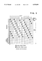
- FIG. 5 is an explanatory view illustrating an example of frequency hopping patterns.
- frequency hopping is performed every frame, and the hopping period is 20 frames.
- One hopping period is divided up into 20 time slots. Accordingly, one frame is present in one time slot.
- T1, T2, . . . represent time slots
- F1, F2, . . . represent frequency channels.
- the frequency channels shown in FIG. 2 correspond to 2.484 GHz ⁇ 13 MHz for which use of spread-spectrum schemes, the foremost of which is frequency hopping, are allowed in Japan.
- FIG. 6 is an explanatory view illustrating a communication frame (referred to as a "PCF” below) used in communication between a main unit and a terminal device and a communication frame (referred to as a "PPF” below) used in communication between terminal devices.
- FIG. 7 is an explanatory view illustrating the structure of an FSYN frame and LCCH-T frame as well the structure of an LCCH-R frame.
- FIG. 8 is an explanatory view illustrating the structure of a Tn frame of T1 ⁇ T4 and the structure of an Rn frame of R1 ⁇ R4.
- FSYN represents a frame which transmits information necessary for the entirety of the frames.
- LCCH-T represents a logical control channel sent from the main unit to the terminal device
- LCCH-R represents a logical control channel sent from the terminal device to the main unit.
- These logical control channels are frames for an exchange of logical control information (LCCH) needed in communication, such as a connect request, disconnect request and connection information for specifying a party, such as telephone dialing information and LAN network address information.
- LCCH logical control information
- each terminal device performs an exchange of LCCH in a time slot allocated by the main unit when communication is taking place.
- Tn and Rn represent communication channels used in communication.
- the communication channel Tn in the PCF frame is used when the main unit makes a transmission to a terminal device
- the channel Tn in the PPF frame is used when a terminal device that has originated a call makes a transmission to the main unit.
- the channel Rn in the PCF frame is used when a terminal device makes a transmission to the main unit
- the channel Rn in the PPF frame is used when a terminal device on the called side makes a transmission.
- CF frequency switching time, which is equivalent to 174 ⁇ s
- CS clearance time equivalent to 12.8 ⁇ s
- R represents a ramp bit equivalent to 6.4 ⁇ s, which covers send/receive changeover time.
- PR is a 62-bit preamble for achieving synchronization
- SYN is a 31-bit frame sync signal
- ID is a 63-bit call signal
- FI represents frame identification information, which is used to distinguish between PPF and PCF.
- TS and NF each represents 8-bit auxiliary information for hopping
- UW is an 8-bit unique word
- D is D-channel information
- B is B-channel information
- GT is guard time
- TR is guard time for send/receive changeover
- RV represents a reserve bit.
- An embodiment of the invention will be described taking as an example a case in which a certain terminal device A places an extension call to another terminal device B.
- FIG. 9 is an explanatory view illustrating the sequence of control data in the main unit, terminal device A and terminal device B in extension communication.
- FIGS. 10, 11 and 12 are flowcharts illustrating the processing executed by the main unit, the calling terminal device A and the called terminal device B.
- FIGS. 9 through 12 primarily describe the processing that is related to the present invention.
- the main unit monitors the status of communication of all of the communication devices in the system (step S1001).
- the results of monitoring indicate whether communication is in the progress and, in case of communication, they indicate the hopping pattern being used as well as the particular communication channel being specified in a frame.
- the results are stored in memory in regard to the item in question.
- the hopping pattern used in communication between the terminal devices and the hopping pattern used in communication between the main unit and terminal device are selected in such a manner that the same frequency channel will not be used simultaneously in each case.
- the main unit gives notification of just how much the hopping pattern used in communication between the terminal devices is to be shifted in time from the hopping pattern used in communication between the main unit and the terminal device.
- the first hopping pattern shown in FIG. 5 is adopted as the hopping pattern used in communication between the main unit and the terminal device.
- the second hopping pattern is adopted as a hopping pattern allocated for the purpose of extension communication. It will be understood from FIG. 5 that the second hopping pattern is obtained by delaying the first hopping pattern by four time slots.
- connection information such as dialing information or address information
- connection information such as dialing information or address information
- the terminal device A sends an extension communication request signal 9002 to the main unit (S1101).
- This request signal is the LCCH-R contained in the PCF frame of FIG. 6 and is sent from the terminal device A to the main unit.
- the main unit refers to the above-mentioned results of monitoring, allocates resources for the communication requested and, together with these resources, sends an extension communication enable signal 9004 to the terminal device Aby way of the logical control channel LCCH-T (S1002).
- the resources include the slot number of an unused communication channel in the PPF frame and the number of time slots the hopping pattern should be shifted to obtain the hopping pattern of the PPF frame.
- notification is given of the fact that the call request has been accepted. In this embodiment, notification is given so as to use a hopping pattern that has been delayed by four time slots.
- the main unit transmits notification of the fact that extension communication is not allowed (S1003) and terminates processing.
- the terminal device A Upon receiving the extension communication enable signal 9004 and the above-mentioned resources ("YES at S1102), the terminal device A stores these resources in memory and sends a connection information signal 9008 to the main, unit by utilizing the LCCH-T (S1104).
- the main unit Upon receiving the connection information signal 9008 ("YES" at S1105), the main unit refers to this connection information 9008 and the memory storing the monitored status of the terminal devices in the system and verifies whether the terminal device B whose connection has been requested by terminal device A is currently communicating. If the terminal device B is currently communicating, then the main unit sends a signal indicative of communication in progress back to the terminal device A, releases the resources and ends processing.
- the main unit notifies the terminal device B of a call termination request by an extension termination signal 9010 using the logical control channel LCCH-T. Further, the main unit notifies of resources such as the slot number of the communication channel used in the PPF frame necessary for communication and the number of time slots the hopping pattern should be shifted to obtain the hopping pattern of the PPF frame (S1006).
- the terminal device B Upon receiving the extension termination signal 9010 and the resources, the terminal device B stores these resources, sends incoming-call request acknowledgment 9012 to the main unit and notifies the user of the incoming call (S1202). Further, on the basis of the stored resources, the terminal device B changes to the hopping pattern specified by the main unit. When the user takes the handset off the hook ("YES" at S1203), the terminal device B transmits an answer signal to the main unit (S1204).
- the main unit Upon receiving an answer from the terminal device B (S1007), the main unit notifies the terminal device A, by way of an extension answer signal 9014, of the fact that an answer has been received from the terminal device B (S1008).
- the terminal device A Upon receiving the extension answer signal 9014, the terminal device A, on the basis of the stored resources, changes to the hopping pattern specified by the main unit and calls the terminal device B without the intermediary of the main unit (S1106). Thereafter, the terminal device A and the terminal device B communicate with each other, without the intermediary of the main unit, using the PPF frame shown in FIG. 6.
- the terminal device A When the terminal device B answers, the terminal device A so informs the main unit by a line connection completion signal 9006 utilizing LCCH-R of the PCF frame (S1009, S1107). As are sult, the main unit sends an extension communication start signal 9016 to the terminal devices A and B. When the terminal device B receives the extension communication start signal 9016, it transmits a line connection completion signal 9018 to the main unit (S1205, S1206).
- the terminal device A calls the terminal device B a number of times and uses LCCH-R to notify the main unit of the fact that the terminal device B does not answer.
- the PPF frame is changed to the PCF frame and communication takes place via the main unit.
- the terminal device A receives the extension communication start signal 9016 from the main unit (S1108) and the terminal device B transmits the line connection completion signal (S1206), the connection between the terminal devices A and B is completed and these terminal devices begin communicating (S1109, S1207).
- an on-hook signal is sent to either of the terminal devices.
- an on-hook signal 9020 is sent from the terminal device A to the terminal device B.
- the on-hook signal 9020 is sent to the terminal device B from the terminal device A when an operation equivalent to hanging up is performed by the terminal device A.
- the terminal device B Upon receiving the on-hook signal 9020 from the terminal device A, the terminal device B sends an on-hook acknowledgment signal 9021 back to the terminal device A (S1110 ⁇ S1112, S1208, S1209).
- the terminal device A Upon receiving the on-hook acknowledgment signal 9021 from the terminal device B, the terminal device A sends an extension communication end signal 9023 to the main unit by utilizing the LCCH-R (S1113).
- the main unit Upon receiving the extension communication end signal 9023, the main unit uses the LCCH-T to transmit line disconnect signals 9025, 9027 to the terminal devices A and B and releases resources (S1010 ⁇ S1012). After the line disconnect signals 9025, 9027 are received (S1114, S1210), the terminal devices A and B return to the hopping pattern for communication between the main unit terminal devices and enter a standby state in which only the LCCH is exchanged with the main unit and in which the next signal is awaited (S1115, S1211).
- the main unit responds to a terminal device vs. terminal device communication request from a terminal device by notifying this terminal device of the hopping pattern being used between the main unit and the terminal device as well as of the extent to which the hopping pattern is to be shifted in terms of time. This makes it possible to increase the number of system lines through a simple arrangement.
- the time needed to notify a terminal device of hopping patterns can be shortened by a wide margin.
- the hopping patterns used in communication with the main unit are stored by the terminal device and the terminal device need only communicate upon effecting a shift in time of which it has been notified by the main unit. This makes it possible to reduce the capacity of the memory used to store hopping patterns.
Landscapes
- Engineering & Computer Science (AREA)
- Computer Networks & Wireless Communication (AREA)
- Signal Processing (AREA)
- Mobile Radio Communication Systems (AREA)
- Small-Scale Networks (AREA)
Applications Claiming Priority (4)
| Application Number | Priority Date | Filing Date | Title |
|---|---|---|---|
| JP7-297757 | 1995-10-20 | ||
| JP29775795 | 1995-10-20 | ||
| JP8-272255 | 1996-10-15 | ||
| JP27225596A JP3320321B2 (ja) | 1995-10-20 | 1996-10-15 | 無線通信システム、無線制御装置、無線通信装置及びそれらの制御方法 |
Publications (1)
| Publication Number | Publication Date |
|---|---|
| US6078609A true US6078609A (en) | 2000-06-20 |
Family
ID=26550104
Family Applications (1)
| Application Number | Title | Priority Date | Filing Date |
|---|---|---|---|
| US08/732,715 Expired - Lifetime US6078609A (en) | 1995-10-20 | 1996-10-18 | Radio communication system using frequency hopping, and method of controlling same |
Country Status (2)
| Country | Link |
|---|---|
| US (1) | US6078609A (ja) |
| JP (1) | JP3320321B2 (ja) |
Cited By (15)
| Publication number | Priority date | Publication date | Assignee | Title |
|---|---|---|---|---|
| US20020026492A1 (en) * | 2000-08-22 | 2002-02-28 | Shigeru Fujita | Communications equipment that carries out communication within network having plural pieces of communications equipment |
| DE10061692C1 (de) * | 2000-12-12 | 2002-06-27 | Fraunhofer Ges Forschung | Basisstation, Mobilteil und Kommunikationsnetz |
| US6587453B1 (en) * | 1997-12-17 | 2003-07-01 | Hewlett-Packard Company | Method of communicating first and second data types |
| US20030226055A1 (en) * | 2002-03-12 | 2003-12-04 | Seiko Epson Corporation | Controller of electronic equipment and clock skew adjusting method |
| US20040125239A1 (en) * | 2002-12-26 | 2004-07-01 | David Rahn | Television tuner supporting channel hopping |
| US20060136603A1 (en) * | 1999-03-04 | 2006-06-22 | Canon Kabushiki Kaisha | Method and device for communicating a message on a network and systems using them |
| US7639744B1 (en) * | 1999-06-25 | 2009-12-29 | Infineon Technologies Ag | Programmable digital bandpass filter for a codec circuit |
| EP2187678A1 (en) * | 2007-10-01 | 2010-05-19 | NTT DoCoMo, Inc. | Signal sequence generation method, control information generation device, and user device |
| US20100165964A1 (en) * | 2008-12-26 | 2010-07-01 | Canon Kabushiki Kaisha | Wireless communication apparatus, a wireless communication method and a computer program |
| US20100189057A1 (en) * | 2009-01-26 | 2010-07-29 | Canon Kabushiki Kaisha | Communication channel determination method and a determination apparatus |
| US20110234404A1 (en) * | 2010-03-23 | 2011-09-29 | Mitsubishi Electric Corporation | Intrusion detection system and sensor device thereof |
| US20110234127A1 (en) * | 2010-03-23 | 2011-09-29 | Mitsubishi Electric Corporation | Current limiting device for vehicle |
| US8686916B2 (en) | 2010-07-13 | 2014-04-01 | Canon Kabushiki Kaisha | Loop antenna |
| US9564685B2 (en) | 2013-06-25 | 2017-02-07 | Canon Kabushiki Kaisha | Antenna and communication apparatus |
| US11368186B2 (en) * | 2017-04-11 | 2022-06-21 | Fraunhofer-Gesellschaft Zur Foerderung Der Angewandten Forschung E.V. | Transmitter and receiver and corresponding methods |
Families Citing this family (1)
| Publication number | Priority date | Publication date | Assignee | Title |
|---|---|---|---|---|
| JP5149338B2 (ja) * | 2010-06-14 | 2013-02-20 | 株式会社エヌ・ティ・ティ・ドコモ | 基地局及び受信方法 |
Citations (9)
| Publication number | Priority date | Publication date | Assignee | Title |
|---|---|---|---|---|
| US586142A (en) * | 1897-07-13 | And hartford | ||
| US5339331A (en) * | 1993-09-09 | 1994-08-16 | Lockheed Corporation | Frequency hopping spread spectrum receiver |
| US5394433A (en) * | 1993-04-22 | 1995-02-28 | International Business Machines Corporation | Frequency hopping pattern assignment and control in multiple autonomous collocated radio networks |
| US5428602A (en) * | 1990-11-15 | 1995-06-27 | Telenokia Oy | Frequency-hopping arrangement for a radio communication system |
| US5459760A (en) * | 1993-11-05 | 1995-10-17 | Matsushita Electric Industrial Co., Ltd. | Transmitting and receiving apparatus |
| US5463659A (en) * | 1994-07-05 | 1995-10-31 | At&T Ipm Corp. | Apparatus and method of configuring a cordless telephone for operating in a frequency hopping system |
| US5506863A (en) * | 1993-08-25 | 1996-04-09 | Motorola, Inc. | Method and apparatus for operating with a hopping control channel in a communication system |
| US5541954A (en) * | 1993-11-24 | 1996-07-30 | Sanyo Electric Co., Ltd. | Frequency hopping communication method and apparatus changing a hopping frequency as a result of a counted number of errors |
| US5748669A (en) * | 1995-04-27 | 1998-05-05 | Sumitomo Electric Industries, Ltd. | Method and apparatus for transmitting information converted to spread spectrum signal |
-
1996
- 1996-10-15 JP JP27225596A patent/JP3320321B2/ja not_active Expired - Fee Related
- 1996-10-18 US US08/732,715 patent/US6078609A/en not_active Expired - Lifetime
Patent Citations (9)
| Publication number | Priority date | Publication date | Assignee | Title |
|---|---|---|---|---|
| US586142A (en) * | 1897-07-13 | And hartford | ||
| US5428602A (en) * | 1990-11-15 | 1995-06-27 | Telenokia Oy | Frequency-hopping arrangement for a radio communication system |
| US5394433A (en) * | 1993-04-22 | 1995-02-28 | International Business Machines Corporation | Frequency hopping pattern assignment and control in multiple autonomous collocated radio networks |
| US5506863A (en) * | 1993-08-25 | 1996-04-09 | Motorola, Inc. | Method and apparatus for operating with a hopping control channel in a communication system |
| US5339331A (en) * | 1993-09-09 | 1994-08-16 | Lockheed Corporation | Frequency hopping spread spectrum receiver |
| US5459760A (en) * | 1993-11-05 | 1995-10-17 | Matsushita Electric Industrial Co., Ltd. | Transmitting and receiving apparatus |
| US5541954A (en) * | 1993-11-24 | 1996-07-30 | Sanyo Electric Co., Ltd. | Frequency hopping communication method and apparatus changing a hopping frequency as a result of a counted number of errors |
| US5463659A (en) * | 1994-07-05 | 1995-10-31 | At&T Ipm Corp. | Apparatus and method of configuring a cordless telephone for operating in a frequency hopping system |
| US5748669A (en) * | 1995-04-27 | 1998-05-05 | Sumitomo Electric Industries, Ltd. | Method and apparatus for transmitting information converted to spread spectrum signal |
Cited By (29)
| Publication number | Priority date | Publication date | Assignee | Title |
|---|---|---|---|---|
| US6587453B1 (en) * | 1997-12-17 | 2003-07-01 | Hewlett-Packard Company | Method of communicating first and second data types |
| US7747783B2 (en) | 1999-03-04 | 2010-06-29 | Canon Kabushiki Kaisha | Method and device for communicating a message on a network and systems using them |
| US20060136603A1 (en) * | 1999-03-04 | 2006-06-22 | Canon Kabushiki Kaisha | Method and device for communicating a message on a network and systems using them |
| US7159042B1 (en) * | 1999-03-04 | 2007-01-02 | Canon Kabushiki Kaisha | Method and device for communicating a message on a network and systems using them |
| US7639744B1 (en) * | 1999-06-25 | 2009-12-29 | Infineon Technologies Ag | Programmable digital bandpass filter for a codec circuit |
| US7088691B2 (en) | 2000-08-22 | 2006-08-08 | Canon Kabushiki Kaisha | Communications equipment that carries out communication within network having plural pieces of communications equipment |
| US20020026492A1 (en) * | 2000-08-22 | 2002-02-28 | Shigeru Fujita | Communications equipment that carries out communication within network having plural pieces of communications equipment |
| DE10061692C1 (de) * | 2000-12-12 | 2002-06-27 | Fraunhofer Ges Forschung | Basisstation, Mobilteil und Kommunikationsnetz |
| US20030226055A1 (en) * | 2002-03-12 | 2003-12-04 | Seiko Epson Corporation | Controller of electronic equipment and clock skew adjusting method |
| US20040125239A1 (en) * | 2002-12-26 | 2004-07-01 | David Rahn | Television tuner supporting channel hopping |
| RU2521415C2 (ru) * | 2007-10-01 | 2014-06-27 | Нтт Досомо, Инк. | Терминал пользователя (варианты), способ передачи сигнала (варианты) и система связи (варианты) |
| EP2187678A4 (en) * | 2007-10-01 | 2014-08-06 | Ntt Docomo Inc | SIGNAL SEQUENCE GENERATION METHOD, CONTROL INFORMATION GENERATING DEVICE, AND USER DEVICE |
| US20100272152A1 (en) * | 2007-10-01 | 2010-10-28 | Ntt Docomo, Inc. | Signal sequence generating method, control information generating apparatus and user equipment terminal |
| CN102904607B (zh) * | 2007-10-01 | 2016-08-10 | 株式会社Ntt都科摩 | 用户装置、发送方法、通信系统、基站、及接收方法 |
| US8223816B2 (en) | 2007-10-01 | 2012-07-17 | Ntt Docomo, Inc. | Signal sequence generating method, control information generating apparatus and user equipment terminal |
| CN102904607A (zh) * | 2007-10-01 | 2013-01-30 | 株式会社Ntt都科摩 | 用户装置、发送方法、通信系统、基站、及接收方法 |
| AU2008308184B2 (en) * | 2007-10-01 | 2013-07-18 | Ntt Docomo, Inc. | Signal sequence generating method, control information generating apparatus and user equipment terminal |
| EP2187678A1 (en) * | 2007-10-01 | 2010-05-19 | NTT DoCoMo, Inc. | Signal sequence generation method, control information generation device, and user device |
| US20100165964A1 (en) * | 2008-12-26 | 2010-07-01 | Canon Kabushiki Kaisha | Wireless communication apparatus, a wireless communication method and a computer program |
| US8995355B2 (en) | 2008-12-26 | 2015-03-31 | Canon Kabushiki Kaisha | Wireless communication apparatus, method and a computer program enabling switching of communication channel based on interference detection |
| US20100189057A1 (en) * | 2009-01-26 | 2010-07-29 | Canon Kabushiki Kaisha | Communication channel determination method and a determination apparatus |
| US9088987B2 (en) | 2009-01-26 | 2015-07-21 | Canon Kabushiki Kaisha | Communication channel determination method and a determination apparatus |
| US20110234127A1 (en) * | 2010-03-23 | 2011-09-29 | Mitsubishi Electric Corporation | Current limiting device for vehicle |
| US8901865B2 (en) | 2010-03-23 | 2014-12-02 | Mitsubishi Electric Corporation | Current limiting device for vehicle |
| US8390449B2 (en) | 2010-03-23 | 2013-03-05 | Mitsubishi Electric Corporation | Intrusion detection system and sensor device thereof |
| US20110234404A1 (en) * | 2010-03-23 | 2011-09-29 | Mitsubishi Electric Corporation | Intrusion detection system and sensor device thereof |
| US8686916B2 (en) | 2010-07-13 | 2014-04-01 | Canon Kabushiki Kaisha | Loop antenna |
| US9564685B2 (en) | 2013-06-25 | 2017-02-07 | Canon Kabushiki Kaisha | Antenna and communication apparatus |
| US11368186B2 (en) * | 2017-04-11 | 2022-06-21 | Fraunhofer-Gesellschaft Zur Foerderung Der Angewandten Forschung E.V. | Transmitter and receiver and corresponding methods |
Also Published As
| Publication number | Publication date |
|---|---|
| JPH09172394A (ja) | 1997-06-30 |
| JP3320321B2 (ja) | 2002-09-03 |
Similar Documents
| Publication | Publication Date | Title |
|---|---|---|
| US6078609A (en) | Radio communication system using frequency hopping, and method of controlling same | |
| US6263210B1 (en) | Wireless communication system and method of controlling same | |
| EP0798874B1 (en) | Wireless communication system using frequency hopping, and method of controlling the system | |
| US5995844A (en) | Wireless telephone system | |
| JP3034282B2 (ja) | 非同期型移動無線通信システム | |
| JP3262966B2 (ja) | 通信装置及びその制御方法 | |
| EP0774842B1 (en) | Wireless telecommunication system using frequency hopping, and method of controlling same | |
| US6115612A (en) | Wireless telephone system having a free period allocated to switching between two frequencies | |
| EP0741950B1 (en) | Ct2 telephone system | |
| JPH09261161A (ja) | 無線通信システム | |
| JP3135485B2 (ja) | 無線通信装置 | |
| JP3397561B2 (ja) | 無線通信システム | |
| EP0739573B1 (en) | Method and equipment for adapting ct2 calls for an isdn subscriber line | |
| JP3703203B2 (ja) | 無線通信システムおよび無線通信方法 | |
| WO1999026445A1 (en) | Multi-channel communication system for wireless local loop communication | |
| JP2950259B2 (ja) | デジタルコードレス電話システム及びその通信方法 | |
| KR0145882B1 (ko) | 구내 무선 전화시스템 | |
| JP3445044B2 (ja) | 無線交換システムおよび無線端末 | |
| JPH09182139A (ja) | 無線交換システム | |
| JPH09191484A (ja) | 無線交換システム | |
| JPH09321738A (ja) | 無線通信システム | |
| JPH08116573A (ja) | コードレス電話方式 | |
| JP2000341206A (ja) | 無線通信システム、無線通信端末、及びデータ端末 | |
| JPH10174146A (ja) | 無線端末情報通知方法 | |
| JPH09294294A (ja) | 無線通信システム |
Legal Events
| Date | Code | Title | Description |
|---|---|---|---|
| AS | Assignment |
Owner name: CANON KABUSHIKI KAISHA, JAPAN Free format text: ASSIGNMENT OF ASSIGNORS INTEREST;ASSIGNOR:NAGO, HIDETADA;REEL/FRAME:008279/0866 Effective date: 19961004 |
|
| STCF | Information on status: patent grant |
Free format text: PATENTED CASE |
|
| CC | Certificate of correction | ||
| FEPP | Fee payment procedure |
Free format text: PAYOR NUMBER ASSIGNED (ORIGINAL EVENT CODE: ASPN); ENTITY STATUS OF PATENT OWNER: LARGE ENTITY |
|
| FPAY | Fee payment |
Year of fee payment: 4 |
|
| FPAY | Fee payment |
Year of fee payment: 8 |
|
| FPAY | Fee payment |
Year of fee payment: 12 |