US6025613A - Semiconductor device capable of reducing leak current and having excellent pinch-off characteristic and method of manufacturing the same - Google Patents
Semiconductor device capable of reducing leak current and having excellent pinch-off characteristic and method of manufacturing the same Download PDFInfo
- Publication number
- US6025613A US6025613A US09/022,384 US2238498A US6025613A US 6025613 A US6025613 A US 6025613A US 2238498 A US2238498 A US 2238498A US 6025613 A US6025613 A US 6025613A
- Authority
- US
- United States
- Prior art keywords
- layer
- inp
- undoped
- semiconductor device
- thickness
- Prior art date
- Legal status (The legal status is an assumption and is not a legal conclusion. Google has not performed a legal analysis and makes no representation as to the accuracy of the status listed.)
- Expired - Fee Related
Links
- 239000004065 semiconductor Substances 0.000 title claims abstract description 110
- 238000004519 manufacturing process Methods 0.000 title abstract description 32
- 125000006850 spacer group Chemical group 0.000 claims abstract description 55
- 229910004205 SiNX Inorganic materials 0.000 claims abstract description 47
- 239000000203 mixture Substances 0.000 claims description 39
- 239000013078 crystal Substances 0.000 claims description 28
- 229910000980 Aluminium gallium arsenide Inorganic materials 0.000 claims description 16
- 229910001218 Gallium arsenide Inorganic materials 0.000 claims description 12
- 230000005669 field effect Effects 0.000 claims description 12
- 238000000034 method Methods 0.000 abstract description 67
- 239000000758 substrate Substances 0.000 abstract description 62
- 230000008020 evaporation Effects 0.000 abstract description 13
- 238000001704 evaporation Methods 0.000 abstract description 13
- 238000002161 passivation Methods 0.000 abstract description 10
- 150000004767 nitrides Chemical class 0.000 abstract description 9
- 238000005268 plasma chemical vapour deposition Methods 0.000 abstract description 4
- 238000010884 ion-beam technique Methods 0.000 abstract description 2
- 238000005530 etching Methods 0.000 description 32
- 125000005842 heteroatom Chemical group 0.000 description 29
- KRHYYFGTRYWZRS-UHFFFAOYSA-N Fluorane Chemical compound F KRHYYFGTRYWZRS-UHFFFAOYSA-N 0.000 description 23
- 229960002050 hydrofluoric acid Drugs 0.000 description 23
- 230000015556 catabolic process Effects 0.000 description 14
- 230000000694 effects Effects 0.000 description 14
- 238000005275 alloying Methods 0.000 description 11
- 230000004888 barrier function Effects 0.000 description 10
- 230000007547 defect Effects 0.000 description 10
- 239000006185 dispersion Substances 0.000 description 10
- 238000005468 ion implantation Methods 0.000 description 8
- 238000000407 epitaxy Methods 0.000 description 7
- BHEPBYXIRTUNPN-UHFFFAOYSA-N hydridophosphorus(.) (triplet) Chemical compound [PH] BHEPBYXIRTUNPN-UHFFFAOYSA-N 0.000 description 4
- 238000002513 implantation Methods 0.000 description 4
- 230000007423 decrease Effects 0.000 description 2
- 239000002184 metal Substances 0.000 description 2
- 230000003647 oxidation Effects 0.000 description 2
- 238000007254 oxidation reaction Methods 0.000 description 2
- 230000027756 respiratory electron transport chain Effects 0.000 description 2
- VYPSYNLAJGMNEJ-UHFFFAOYSA-N Silicium dioxide Chemical compound O=[Si]=O VYPSYNLAJGMNEJ-UHFFFAOYSA-N 0.000 description 1
- 238000000137 annealing Methods 0.000 description 1
- 238000005229 chemical vapour deposition Methods 0.000 description 1
- 230000003247 decreasing effect Effects 0.000 description 1
- 238000000151 deposition Methods 0.000 description 1
- 230000002542 deteriorative effect Effects 0.000 description 1
- 239000011521 glass Substances 0.000 description 1
- 238000009413 insulation Methods 0.000 description 1
- 150000002500 ions Chemical class 0.000 description 1
- 239000000463 material Substances 0.000 description 1
- 229910044991 metal oxide Inorganic materials 0.000 description 1
- 150000004706 metal oxides Chemical class 0.000 description 1
- 229910052814 silicon oxide Inorganic materials 0.000 description 1
- 238000001039 wet etching Methods 0.000 description 1
Images


Classifications
-
- H—ELECTRICITY
- H01—ELECTRIC ELEMENTS
- H01L—SEMICONDUCTOR DEVICES NOT COVERED BY CLASS H10
- H01L29/00—Semiconductor devices adapted for rectifying, amplifying, oscillating or switching, or capacitors or resistors with at least one potential-jump barrier or surface barrier, e.g. PN junction depletion layer or carrier concentration layer; Details of semiconductor bodies or of electrodes thereof ; Multistep manufacturing processes therefor
- H01L29/66—Types of semiconductor device ; Multistep manufacturing processes therefor
- H01L29/66007—Multistep manufacturing processes
- H01L29/66075—Multistep manufacturing processes of devices having semiconductor bodies comprising group 14 or group 13/15 materials
- H01L29/66227—Multistep manufacturing processes of devices having semiconductor bodies comprising group 14 or group 13/15 materials the devices being controllable only by the electric current supplied or the electric potential applied, to an electrode which does not carry the current to be rectified, amplified or switched, e.g. three-terminal devices
- H01L29/66409—Unipolar field-effect transistors
- H01L29/66848—Unipolar field-effect transistors with a Schottky gate, i.e. MESFET
- H01L29/66856—Unipolar field-effect transistors with a Schottky gate, i.e. MESFET with an active layer made of a group 13/15 material
- H01L29/66863—Lateral single gate transistors
-
- H—ELECTRICITY
- H01—ELECTRIC ELEMENTS
- H01L—SEMICONDUCTOR DEVICES NOT COVERED BY CLASS H10
- H01L29/00—Semiconductor devices adapted for rectifying, amplifying, oscillating or switching, or capacitors or resistors with at least one potential-jump barrier or surface barrier, e.g. PN junction depletion layer or carrier concentration layer; Details of semiconductor bodies or of electrodes thereof ; Multistep manufacturing processes therefor
- H01L29/66—Types of semiconductor device ; Multistep manufacturing processes therefor
- H01L29/66007—Multistep manufacturing processes
- H01L29/66075—Multistep manufacturing processes of devices having semiconductor bodies comprising group 14 or group 13/15 materials
- H01L29/66227—Multistep manufacturing processes of devices having semiconductor bodies comprising group 14 or group 13/15 materials the devices being controllable only by the electric current supplied or the electric potential applied, to an electrode which does not carry the current to be rectified, amplified or switched, e.g. three-terminal devices
- H01L29/66409—Unipolar field-effect transistors
- H01L29/66446—Unipolar field-effect transistors with an active layer made of a group 13/15 material, e.g. group 13/15 velocity modulation transistor [VMT], group 13/15 negative resistance FET [NERFET]
- H01L29/66462—Unipolar field-effect transistors with an active layer made of a group 13/15 material, e.g. group 13/15 velocity modulation transistor [VMT], group 13/15 negative resistance FET [NERFET] with a heterojunction interface channel or gate, e.g. HFET, HIGFET, SISFET, HJFET, HEMT
Definitions
- This invention relates to a semiconductor device which has an InP layer and a method of manufacturing the semiconductor device.
- InP has been recognized as an attractive material for channels of power semiconductor devices, such as a power field effect transistor (FET), because of its high peak electron velocity, high thermal conductivity, and high breakdown field.
- FET power field effect transistor
- Several types of the semiconductor devices have been reported as such one having an InP channel, those are MESFET, MISFET, Retero MISFET, and the like.
- a conventional MISFET or Hetero MISFET comprises a thick silicon oxide or a thick hetero semiconductor crystal inserted between a gate and a shotkey layer for the purpose of reducing leak current from the gate. Further, the conventional MISFET or Hetero MISFET also comprises a thick insulation film or a thick hetero semiconductor crystal interposed between a metal gate and a channel for the purpose of improving gate breakdown voltage. As a result, a distance therebetween becomes large and decreases mutual conductance.
- the InP layer and the hetero semiconductor crystal including no P (phosphorous) are continuously grown by the use of molecular beam epitaxiy (MBE) or metal organic chemical vapor deposition (MOCVD), a source of phosphorous must be changed.
- MBE molecular beam epitaxiy
- MOCVD metal organic chemical vapor deposition
- a source of phosphorous must be changed.
- it is very difficult to control the flow of phosphorous because of its extremely high vapor pressure. Consequently, a steep hetero interface cannot be obtained in the conventional Hetero MISFET. Accordingly, a conduction band profile is disarranged.
- the hetero semiconductor crystal including no phosphorous is grown on the InP layer, an electron transfer characteristic in the InP layer is deteriorated.
- a method of manufacturing a semiconductor device which consists mainly of a semiconductor crystal having an InP layer, the method comprising the steps of: (A) removing an oxide InP by a processing selected from the group consisting of N 2 H 4 plasma processing, N 3 H 6 plasma processing, NH 3 plasma processing, and N 2 plasma processing; and (B) forming SiNx layer on the InP layer.
- the method may comprise the steps of: (A) making a surface of the InP layer be subjected to a processing selected from the group consisting of N 2 H 4 plasma processing, N 3 H 6 plasma processing, NH 3 plasma processing, and N 2 plasma processing to form an InN film on the surface of the InP layer; and (B) forming SiNx layer on the InN film.
- the method may comprise the steps of: (A) removing an oxide InP by a processing selected from the group consisting of N 2 H 4 plasma processing, N 3 H 6 plasma processing, NH 3 plasma processing, and N 2 plasma processing; and (B) forming an InN film on a surface of the InP layer by the same processing as that of the removing an oxide InP step selected from the group consisting of N 2 H 4 plasma processing, N 3 H 6 plasma processing, NH 3 plasma processing, and N 2 plasma processing.
- a method of manufacturing a semiconductor device comprising the steps of: (A) forming a primary layer having a primary composition of InP; and (B) forming a secondary layer on the primary layer; the secondary layer having a secondary composition selected from the group consisting of AlGaAs, GaAs, AlInP, AlGaP, and AlGaInP.
- the method may comprise the steps of: (A) forming a primary layer having a primary composition of InP; and (B) forming a secondary layer on the primary layer; the secondary layer comprising two layers selected from the group consisting of two layers of AlGaAs and AlInAs, two layers of GaAs and AlInAs, two layers of AlInP and AlInAs, two layers of AlGaP and AlInAs, and two layers of AlGaInP and AlInAs.
- the method may comprise the steps of: (A) forming a primary layer having a primary composition of InP; and (B) forming a secondary layer on the primary layer; the secondary layer comprising three layers selected from the group consisting of three layers of AlGaAs, AlInAs and AlGaAs, three layers of GaAs, AlInAs and GaAs, three layers of AlInP, AlInAs and AlInP, three layers of AlGaP, AlInAs and AlGaP, and three layers of AlGaInP, AlInAs and AlGaInP.
- a field effect transistor which consists mainly of a semiconductor crystal having an InP layer and which includes source, drain and gate electrodes, the field effect transistor comprising: (A) a SiNx spacer layer which separates the source, the drain and the gate electrodes each other; and (B) an InN film formed between the InP layer and the SiNx spacer layer.
- the field effect transistor may comprise: (A) a primary layer having a primary composition of InP; and (B) a secondary layer which is formed on the primary layer and which has a secondary composition selected from the group consisting of AlGaAs, GaAs, AlInP, AlGaP, and AlGaInP.
- the field effect transistor may comprise: (A) a primary layer having a primary composition of InP; and (B) a secondary layer which is formed on the primary layer and which comprises two layers selected from the group consisting of two layers of AlGaAs and AlInAs, two layers of GaAs and AlInAs, two layers of AlInP and AlInAs, two layers of AlGaP and AlInAs, and two layers of AlGaInP and AlInAs.
- the field effect transistor may comprise: (A) a primary layer which defines an InP channel region; and (B) a secondary layer which is formed on the primary layer and which comprises three layers selected from the group consisting of three layers of AlGaAs, AlInAs and AlGaAs, three layers of GaAs, AlInAs and GaAs, three layers of AlInP, AlInAs and AlInP, three layers of AlGaP, AlInAs and AlGaP, and three layers of AlGaInP, AlInAs and AlGaInP.
- FIG. 1 is a schematic vertical sectional view of a conventional semiconductor device
- FIGS. 2A to 2F are schematic vertical sectional views of a semiconductor device at various steps of a method according to a first embodiment of this invention
- FIGS. 3A to 3F are schematic vertical sectional views of a semiconductor device at various steps of a method according to a second embodiment of this invention.
- FIGS. 4A to 4F are schematic vertical sectional views of a semiconductor device at various steps of a method according to a third embodiment of this invention.
- FIGS. 5A to 5F are schematic vertical sectional views of a semiconductor device at various steps of a method according to a fourth embodiment of this invention.
- FIGS. 6A to 6F are schematic vertical sectional views of a semiconductor device at various steps of a method according to a fifth embodiment of this invention.
- FIGS. 7A to 7F are schematic vertical sectional views of a semiconductor device at various steps of a method according to a sixth embodiment of this invention.
- FIGS. 8A to 8F are schematic vertical sectional views of a semiconductor device at various steps of a method according to a seventh embodiment of this invention.
- FIGS. 9A to 9F are schematic vertical sectional views of a semiconductor device at various steps of a method according to an eighth embodiment of this invention.
- FIGS. 10A to 10F are schematic vertical sectional views of a semiconductor device at various steps of a method according to a ninth embodiment of this invention.
- FIGS. 11A to 11F are schematic vertical sectional views of a semiconductor device at various steps of a method according to a tenth embodiment of this invention.
- FIGS. 12A to 12F are schematic vertical sectional views of a semiconductor device at various steps of a method according to an eleventh embodiment of this invention.
- FIG. 1 a conventional semiconductor device will be described at first in order to facilitate an understanding of the present invention.
- the conventional semiconductor device comprises an InP semiconductor substrate 101, a channel region 102 formed in the InP semiconductor substrate 101, a spacer layer or a passivation film 104 formed on the InP semiconductor substrate 101, an InP oxide film 103 formed between the InP semiconductor substrate 101 and a spacer layer or a passivation film 104, a source electrode 105, a drain electrode 106, and a gate electrode 107 each of which is formed on the channel region 102.
- the InP oxide film 103 including In 2 O 3 is formed in an interface between the InP semiconductor substrate 101 and the spacer layer or the passivation film 104.
- large leak current flowing through the InP oxide film 103 inevitably occurs. Consequently, it is very difficult to obtain the conventional semiconductor device capable of reducing the leak current.
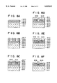
- FIGS. 2A through 2F illustrated are sectional views each of which shows each process of the method of manufacturing the semiconductor device according to the first embodiment.
- a semi-insulated InP substrate 201 is prepared in a known manner.
- the semi-insulated InP substrate 201 has a principal surface directed upwards of FIG. 2.
- Si + ions are implanted into the semi-insulated InP substrate 201 by the use of an implantation mask having opening area for a channel region on conditions that implantation energy is 50 keV and that implantation amount is 4 ⁇ 10 12 cm -2 .
- the implantation mask is then removed.
- An anneal protection film such as glass phosphide is grown on the principal surface of the semi-insulated InP substrate 201.
- the semi-insulated InP substrate 201 is subjected to an activated annealing for fifteen minutes at a temperature of 660° C.
- an InP oxide film 202 is inevitably produced on the semi-insulated InP substrate 201 and the channel region 203, as depicted in FIG. 2A.
- the InP substrate 201 having the InP oxide film 202 in the surface thereof is subjected to NH 3 plasma processing by the use of plasma CVD apparatus into which NH 3 gas is introduced.
- the InP oxide film 202 is deoxided and removed from the surface of the InP substrate 201 by the NH 3 plasma for the deoxidation, as depicted in FIG. 2B.
- an InN (nitride) film 204 is formed on the InP substrate 201 and the channel region 203 to have a thickness of 30 nm, as depicted in FIG. 2C.
- S i H 3 gas and NH 3 gas are introduced into the plasma CVD apparatus.
- a SiNx spacer layer 205 is thereby formed on the InN (nitride) film 204 to have a thickness of 350 nm, as depicted in FIG. 2D.
- the SiNx spacer layer 205 and the InN (nitride) film 204 are etched by fluoric acid.
- an AuGe layer is stacked on the InP channel region 203 by evaporation lift-off and alloying(for example, 400° C./one minute) to form a source electrode 206 and a drain electrode 207, respectively as ohmic electrodes.
- the SiNx spacer layer 205 and the InN (nitride) film 204 are etched by fluoric acid.
- a Pt layer is stacked on the InP channel region 203 by evaporation lift-off or ion beam sputter method to form a gate electrode 208.
- a SiNx/InN passivation film 209 is formed on all over the InP substrate 201 including the source electrode 206, the drain electrode 207, and the gate electrode 208, as illustrated in FIG. 2F. Accordingly, a semiconductor device protected by the passivation film 209 is completed, as illustrated in FIG. 2F.
- NH 3 gas is employed to remove a natural oxidation film and to form an InN (nitride) film.
- N 2 H 4 gas, N 3 H 6 gas, or N 2 gas may be alternatively employed.
- the channel region was formed by ion implantation in the first embodiment, the ion implantation can be replaced with MBE or MOCVD method. In such a case, an undoped Al 0 .48 In 0 .52 As buffer layer, and an InP channel layer of 100 nm thickness with Si of 4 ⁇ 10 17 cm -3 doped are sequentially grown by epitaxy on the semi-insulated InP substrate.
- FIGS. 3A through 3F illustrated are sectional views each of which shows each process of the method of manufacturing the semiconductor device according to the second embodiment.
- a semi-insulated InP substrate 301 is prepared in a known manner.
- the semi-insulated InP substrate 301 has a principal surface directed upwards of FIG. 3.
- cap layer 305 of 50 nm thickness with doped Si of 5 ⁇ 10 18 cm -3 are sequentially grown on the principal surface of the semi-insulated InP substrate 301 by MBE method.
- the undoped Al 0 .48 In 0 .52 As buffer layer 302 is substantially lattice-matched with the semi-insulated InP substrate 301.
- a SiNx spacer layer 306 is formed on the Ga 0 .47 In 0 .53 As cap layer 305 to have a thickness of 350 nm, as depicted in FIG. 3B.
- the SiNx spacer layer 306 is removed by fluoric acid, as illustrated in FIG. 3B.
- an AuGe layer is stacked on the Ga 0 .47 In 0 .53 As cap layer 305 by evaporation lift-off and alloying(for example, 400° C./one minute) to form a source electrode 308 and a drain electrode 309, respectively as ohmic electrodes.
- the SiNx spacer layer 306 is removed by fluoric acid by the use of an etching mask 210 having opening area for a gate electrode region while the Ga 0 .47 In 0 .53 As cap layer 305 is removed by a tartaric etchant, as illustrated in FIG. 3D. Thereafter, a gate electrode 211 of WSi is formed on the undoped Al 0 .3 Ga 0 .7 As Schottky layer 304, as shown in FIG. 3E. The etching mask 210 is then removed. Accordingly, a semiconductor device of the second embodiment is completed, as illustrated in FIG. 3F.
- height of Schottky barrier is as large as 1.0 eV by forming the undoped Al 0 .3 Ga 0 .7 As Schottky layer 304.
- the value is large enough to reduce gate leak current.
- the undoped Al 0 .3 Ga 0 .7 As Schottky layer 304 has a thickness not larger than critical thickness thereof, defect or dislocation does not occur therein (Hereinunder, the critical thickness is the maximum thickness by which dislocation does not occur).
- the density of surface state is within an order of 10 10 cm -2 v -1 .
- distance between the gate and the channel region is small, although a desirable breakdown voltage is achieved. Consequently, an excellent pinch-off characteristic is achieved with a drain voltage of about 15V.
- frequency dispersion is reduced while mutual conductance is prevented from getting smaller in upper portions.
- the mutual conductance was as large as 300 mS/mm.
- the channel region is formed by epitaxial growth.
- the channel region may be alternatively formed by ion implantation.
- an undoped Al 0 .3 Ga 0 .7 As Schottky layer having a thickness of 5 nm, and a Ga 0 .47 In 0 .53 As cap layer of 50 nm thickness with doped Si of 5 ⁇ 10 18 cm -3 are sequentially grown by epitaxy.
- the undoped Al 0 .3 Ga 0 .7 As Schottky layer is employed in the second embodiment.
- a composition of the Schottky layer may be Al x Ga 1-x As (0 ⁇ x ⁇ 1) to obtain the same advantageous effect as the above composition of Al 0 .3 Ga 0 .7 As.
- FIGS. 4A through 4F illustrated are sectional views each of which shows each process of the method of manufacturing the semiconductor device according to the third embodiment.
- a semi-insulated InP substrate 401 is prepared in a known manner.
- the semi-insulated InP substrate 401 has a principal surface directed upwards of FIG. 4.
- an undoped Al 0 .48 In 0 .52 As buffer layer 402 having a thickness of 300 nm
- an InP channel layer 403 having 100 nm thickness with doped Si of 4 ⁇ 10 17 cm -3
- a Schottky layer consisting of two layers of both an undoped Al 0 .48 In 0 .52 As layer 404 having a thickness of 20 nm and an undoped Al 0 .3 Ga 0 .7 As layer 405 having a thickness of 6 nm, and a on the principal surface of the semi-insulated InP substrate 401 by MBE method.
- a SiNx spacer layer 407 is formed on the Ga 0 .47 In 0 .53 As cap layer 406, as depicted in FIG. 4B.
- an etching mask 408 having opening area for an ohmic electrode region
- the SiNx spacer layer 407 is removed by fluoric acid, as illustrated in FIG. 4B.
- an AuGe layer is stacked on the Ga 0 .47 In 0 .53 As cap layer 406 by evaporation lift-off and alloying(for example, 400° C./one minute) to form a source electrode 409 and a drain electrode 410, respectively as ohmic electrodes.
- the SiNx spacer layer 407 is removed by fluoric acid by the use of an etching mask 411 having an opening area for a gate electrode region while the Ga 0 .47 In 0 .53 As cap layer 406 is removed by a tartaric etchant, as illustrated in FIG. 4D. Thereafter, a gate electrode 412 of WSi is formed on the Schottky layer, as shown in FIG. 4E. The etching mask 411 is then removed. Accordingly, a semiconductor device of the third embodiment is completed, as illustrated in FIG. 4F.
- height of Schottky barrier is as large as 1.0 eV by forming the Schottky layer consisting of two layers of both the undoped Al 0 .48 In 0 .52 As layer 404 and the undoped Al 0 .30 Ga 0 .7 As layer 405.
- the value is large enough to reduce gate leak current. Defects or dislocations do not occur in each Al 0 .3 Ga 0 .7 As layer. Further, it becomes possible that the density of surface state is within an order of 10 10 cm 31 2 v -1 .
- distance between the gate and the channel region is small, although a desirable breakdown voltage is achieved. Consequently, an excellent pinch-off characteristic is achieved up to a drain voltage of about 18V.
- frequency dispersion is reduced while mutual conductance is prevented from getting smaller in upper portions. The mutual conductance was as large as 290 mS/mm.
- the channel region is formed by epitaxial growth.
- the channel region may be alternatively formed by ion implantation.
- the Schottky layer consisting of two layers of both the undoped Al 0 .48 In 0 .52 As layer having a thickness of 20 nm and the undoped Al 0 .3 Ga 0 .7 As layer having a thickness of 6 nm, and the Ga 0 .47 In 0 .53 As cap layer of 50 nm thickness with doped Si of 5 ⁇ 10 18 cm -3 are sequentially grown by epitaxy.
- a hetero junction semiconductor crystal is grown on the semi-insulated InP substrate by MBE method in the third embodiment.
- a similar hetero junction semiconductor crystal can be obtained by MOCVD method.
- the Schottky layer having a composition of Al 0 .3 Ga 0 .7 As is employed in the third embodiment.
- a composition of the Schottky layer may be Al x Ga 1-x As (0 ⁇ x ⁇ 1) to obtain the same advantageous effect as the above composition of Al 0 .3 Ga 0 .7 As.
- FIGS. 5A through 5F illustrated are sectional views each of which shows each process of the method of manufacturing the semiconductor device according to the fourth embodiment.
- a semi-insulated InP substrate 501 is prepared in a known manner.
- the semi-insulated InP substrate 501 has a principal surface directed upwards of FIG. 5.
- an undoped Al 0 .48 In 0 .52 As buffer layer 502 having a thickness of 300 nm
- an InP channel layer 503 of 100 nm thickness with doped Si of 4 ⁇ 10 17 cm -3
- a Schottky layer consisting of three layers of an undoped Al 0 .3 Ga 0 .7 As layer 504 having a thickness of 6 nm
- an undoped Al 0 .48 In 0 .52 As layer 505 having a thickness of 13 nm
- an undoped Al 0 .3 Ga 0 .7 As layer 506 having a thickness of 6 nm
- cap layer 507 of 50 nm thickness with doped Si of 5 ⁇ 10 18 cm -3 are sequential
- a SiNx spacer layer 508 is formed on the Ga 0 .47 In 0 .53 As cap layer 507, as depicted in FIG. 5B.
- the SiNx spacer layer 508 is removed by fluoric acid, as illustrated in FIG. 5B.
- an AuGe layer is stacked on the Ga 0 .47 In 0 .53 As cap layer 507 by evaporation lift-off and alloying(for example, 400° C./one minute) to form a source electrode 510 and a drain electrode 511, respectively as ohmic electrodes.
- the SiNx spacer layer 508 is removed by fluoric acid by the use of an etching mask 512 having an opening area for a gate electrode region while the Ga 0 .47 In 0 .53 As cap layer 507 is removed by a tartaric etchant, as illustrated in FIG. 5D. Thereafter, a gate electrode 513 of WSi is formed on the undoped Al 0 .3 Ga 0 .7 As layer 506, as shown in FIG. 5E. The etching mask 512 is then removed. Accordingly, a semiconductor device of the fourth embodiment is completed, as illustrated in FIG. 5F.
- height of Schottky barrier is as large as 1.0 eV by forming the Schottky layer consisting of three layers of the undoped Al 0 .3 Ga 0 .7 As layer 504, the undoped Al 0 .48 In 0 .52 As layer 505 and the undoped Al 0 .3 Ga 0 .7 As layer 506.
- the value is large enough to reduce gate leak current. Defects or dislocations do not occur in each Al 0 .3 Ga 0 .7 As layer. Further, it becomes possible that the density of surface state is within an order of 10 10 cm -2 v -1 .
- distance between the gate and the channel region is small, although a desirable breakdown voltage is achieved. Consequently, an excellent pinch-off characteristic is achieved up to a drain voltage of about 20V.
- frequency dispersion is reduced while mutual conductance is prevented from getting smaller in upper portions. The mutual conductance was as large as 280 mS/mm.
- the channel region is formed by epitaxial growth.
- the channel region may be alternatively formed by ion implantation.
- the Schottky layer consisting of three layers of the undoped Al 0 .3 Ga 0 .7 As layer having a thickness of 6 nm, the undoped Al 0 .48 In 0 .52 As layer having a thickness of 13 nm, and the undoped Al 0 .3 Ga 0 .7 As layer having a thickness of 6 nm, and the Ga 0 .47 In 0 .53 As cap layer of 50 nm thickness with doped Si of 5 ⁇ 10 18 cm -3 are sequentially grown by epitaxy.
- a hetero junction semiconductor crystal is grown on the semi-insulated InP substrate by MBE method in the fourth embodiment.
- a similar hetero junction semiconductor crystal can be obtained by MOCVD method.
- the Schottky layer having a composition of Al 0 .3 Ga 0 .7 As is employed in the fourth embodiment.
- a composition of the Schottky layer may be Al x Ga 1-x As (0 ⁇ x ⁇ 1) to obtain the same advantageous effect as the above composition of Al 0 .3 Ga 0 .7 As.
- FIGS. 6A through 6F illustrated are sectional views each of which shows each process of the method of manufacturing the semiconductor device according to the fifth embodiment.
- a semi-insulated InP substrate 601 is prepared in a known manner.
- the semi-insulated InP substrate 601 has a principal surface directed upwards of FIG. 6.
- a SiNx spacer layer 608 is formed on the Ga 0 .47 In 0 .53 As cap layer 607, as depicted in FIG. 6B.
- the SiNx spacer layer 608 is removed by fluoric acid, as illustrated in FIG. 6B.
- an AuGe layer is stacked on the Ga 0 .47 In 0 .53 As cap layer 607 by evaporation lift-off and alloying(for example, 400° C./one minute) to form a source electrode 610 and a drain electrode 611, respectively as ohmic electrodes.
- the SiNx spacer layer 608 is removed by fluoric acid by the use of an etching mask 612 having an opening area for a gate electrode region while the Ga 0 .47 In 0 .53 As cap layer 607 is removed by a tartaric etchant, as illustrated in FIG. 6D. Thereafter, a gate electrode 613 of WSi is formed on the undoped Al 0 .3 Ga 0 .7 As layer 606, as shown in FIG. 6E. The etching mask 612 is then removed. Accordingly, a semiconductor device of the fifth embodiment is completed, as illustrated in FIG. 6F.
- height of Schottky barrier is as large as 1.0 eV by forming the undoped Al 0 .3 Ga 0 .7 As layer 604, the Al 0 .48 In 0 .52 As electron supplying layer 605 and the undoped Al 0 .3 Ga 0 .7 As spacer layer 606 on the undoped InP channel layer 603.
- the value is large enough to reduce gate leak current. Defects or dislocations do not occur in each Al 0 .3 Ga 0 .7 As layer. Further, it becomes possible that the density of surface state is within an order of 10 10 cm -2 v 9-1 . Moreover, distance between the gate and the channel region is small, although a desirable breakdown voltage is achieved.
- a hetero junction semiconductor crystal is grown on the semi-insulated InP substrate by MBE method.
- a similar hetero junction semiconductor crystal can be obtained by MOCVD method.
- the undoped AlGaAs layer 604 and the undoped AlGaAs spacer layer 606 each having a composition of Al 0 .3 Ga 0 .7 As are employed in the fifth embodiment.
- a composition of each AlGaAs layer 604 or 606 may be Al x Ga 1-x As (0 ⁇ x ⁇ 1) to obtain the same advantageous effect as the above composition of Al 0 .3 Ga 0 .7 As.
- FIGS. 7A through 7F illustrated are sectional views each of which shows each process of the method of manufacturing the semiconductor device according to the sixth embodiment.
- a semi-insulated InP substrate 701 is prepared in a known manner.
- the semi-insulated InP substrate 701 has a principal surface directed upwards of FIG. 7.
- a SiNx spacer layer 707 is formed on the Ga 0 .47 In 0 .53 As cap layer 706, as depicted in FIG. 7B.
- the SiNx spacer layer 707 is removed by fluoric acid, as illustrated in FIG. 7B.
- an AuGe layer is stacked on the Ga 0 .47 In 0 .53 As cap layer 706 by evaporation lift-off and alloying(for example, 400° C./one minute) to form a source electrode 709 and a drain electrode 710, respectively as ohmic electrodes.
- the SiNx spacer layer 707 is removed by fluoric acid by the use of an etching mask 711 having an opening area for a gate electrode region while the Ga 0 .47 In 0 .53 As cap layer 706 is removed by a tartaric etchant, as illustrated in FIG. 7D. Thereafter, a gate electrode 712 of WSi is formed on the undoped Al 0 .3 Ga 0 .7 As layer 705, as shown in FIG. 7E. The etching mask 711 is then removed. Accordingly, a semiconductor device of the sixth embodiment is completed, as illustrated in FIG. 7F.
- height of Schottky barrier is as large as 1.0 eV by forming the undoped Al 0 .3 Ga 0 .7 As layer 705 and the Al 0 .48 In 0 .52 As electron supplying layer 704 on the undoped InP channel layer 703.
- the value is large enough to reduce gate leak current. Defects or dislocations do not occur in each Al 0 .3 Ga 0 .7 As layer. Further, it becomes possible that density of surface state is within an order of 10 10 cm -2 v -1 . Moreover, distance between the gate and the channel region is small, although a desirable breakdown voltage is achieved.
- a hetero junction semiconductor crystal is grown on the semi-insulated InP substrate by MBE method.
- a similar hetero junction semiconductor crystal can be obtained by MOCVD method.
- the undoped AlGaAs layer 705 having a composition of Al 0 .3 Ga 0 .7 As is employed in the sixth embodiment.
- a composition of the undoped AlGaAs layer 705 may be Al x Ga 1-x As (0 ⁇ x ⁇ 1) to obtain the same advantageous effect as the above composition of Al 0 .3 Ga 0 .7 As.
- FIGS. 8A through 8F illustrated are sectional views each of which shows each process of the method of manufacturing the semiconductor device according to the seventh embodiment.
- a semi-insulated InP substrate 801 is prepared in a known manner.
- the semi-insulated InP substrate 801 has a principal surface directed upwards of FIG. 8.
- buffer layer 802 having a thickness of 300 nm
- cap layer 805 of 50 nm thickness with doped Si of 5 ⁇ 10 18 cm -3 are sequentially grown on the principal surface of the semi-insulated InP substrate 801 by MBE method.
- a SiNx spacer layer 806 is formed on the Ga 0 .47 In 0 .53 As cap layer 805, as depicted in FIG. 8B.
- the SiNx spacer layer 806 is removed by fluoric acid, as illustrated in FIG. 8B.
- an AuGe layer is stacked on the Ga 0 .47 In 0 .53 As cap layer 805 by evaporation lift-off and alloying(for example, 400° C./one minute) to form a source electrode 808 and a drain electrode 809, respectively as ohmic electrodes.
- the SiNx spacer layer 806 is removed by fluoric acid by the use of an etching mask 810 having an opening area for a gate electrode region while the Ga 0 .47 In 0 .53 As cap layer 805 is removed by a tartaric etchant, as illustrated in FIG. 8D. Thereafter, a gate electrode 811 of WSi is formed on the undoped Al 0 .3 In 0 .7 P Schottky layer 804, as shown in FIG. 8E. The etching mask 810 is then removed. Accordingly, a semiconductor device of the seventh embodiment is completed, as illustrated in FIG. 8F.
- the InP channel layer 803 and the undoped Al 0 .3 In 0 .7 P Schottky layer 804 are sequentially grown by epitaxy, a steep hetero-interface is successfully formed therebetween. As a result, a channel electron mobility is about 3000 cm- 2 v -1 s -1 . Further, height of Schottky barrier is as large as 0.8 eV by using the Al 0 .3 In 0 .7 P layer as a Schottky layer. The value is large enough to reduce gate leak current. Defects or dislocations do not occur in the Al 0 .3 In 0 .7 P layer.
- the density of surface state is within an order of 10 10 cm -2 v -1 .
- distance between the gate and the channel region is small, although a desirable breakdown voltage is achieved. Consequently, an excellent pinch-off characteristic is achieved up to a drain voltage of about 15V.
- frequency dispersion is reduced while mutual conductance is prevented from getting smaller in upper portions.
- the mutual conductance was as large as 300 mS/mm.
- a hetero junction semiconductor crystal is grown on the semi-insulated InP substrate by MBE method.
- a similar hetero junction semiconductor crystal can be obtained by MOCVD method.
- the undoped AlInP Schottky layer 804 having a composition of Al 0 .3 In 0 .7 P is employed in the seventh embodiment.
- a composition of the undoped AlInP Schottky layer 804 may be Al x In 1-x P (1 ⁇ x ⁇ 1) to obtain the same advantageous effect as the above composition of Al 0 .3 In 0 .7 P.
- an Al x Ga 1-x P (0 ⁇ x ⁇ 1) layer having a thickness not larger than the above-defined critical thickness or an Al x Ga y In 1-x-y P (0 ⁇ x ⁇ 1, 0 ⁇ y ⁇ 1, 0 ⁇ x+y ⁇ 1) layer having a thickness not larger than the above-defined critical thickness may be used to obtain a similar advantageous effect.
- FIGS. 9A through 9F illustrated are sectional views each of which shows each process of the method of manufacturing the semiconductor device according to the eighth embodiment.
- a semi-insulated InP substrate 901 is prepared in a known manner.
- the semi-Insulated InP substrate 901 has a principal surface directed upwards of FIG. 9.
- a SiNx spacer layer 907 of 350 nm thickness is formed on the Ga 0 .47 In 0 .53 As cap layer 906, as depicted in FIG. 9B.
- the SiNx spacer layer 907 is removed by fluoric acid, as illustrated in FIG. 9B.
- an AuGe layer is stacked on the Ga 0 .47 In 0 .53 As cap layer 906 by evaporation lift-off and alloying(for example, 400° C./one minute) to form a source electrode 909 and a drain electrode 910, respectively as ohmic electrodes.
- the SiNx spacer layer 907 is removed by fluoric acid by the use of an etching mask 911 having an opening area for a gate electrode region while the Ga 0 .47 In 0 .53 As cap layer 906 is removed by a tartaric etchant, as illustrated in FIG. 9D. Thereafter, a gate electrode 912 of WSi is formed on the undoped Al 0 .3 In 0 .7 P layer 905, as shown in FIG. 9E. The etching mask 911 is then removed. Accordingly, a semiconductor device of the eighth embodiment is completed, as illustrated in FIG. 9F.
- height of Schottky barrier is as large as 0.8 eV by using the two layers of both the undoped Al 0 .48 In 0 .52 As layer 904 and the undoped Al 0 .3 In 0 .7 P layer 905 as a Schottky layer.
- the value is large enough to reduce gate leak current. Defects or dislocations do not occur in the Al 0 .3 In 0 .7 P layer. Further, it becomes possible the density of surface state is within an order of 10 10 cm -2 v -1 .
- distance between the gate and the channel region is small, although a desirable breakdown voltage is achieved. Consequently, an excellent pinch-off characteristic is achieved up to a drain voltage of about 18V.
- frequency dispersion is reduced while mutual conductance is prevented from getting smaller in upper portions. The mutual conductance was as large as 290 mS/mm.
- a hetero junction semiconductor crystal is grown on the semi-insulated InP substrate by MBE method.
- a similar hetero junction semiconductor crystal can be obtained by MOCVD method.
- the undoped AlInP layer 905 having a composition of Al 0 .3 In 0 .7 P is employed in the eighth embodiment.
- a composition of the undoped AlInP layer 905 may be Al x In 1-x P (0 ⁇ x ⁇ 1) to obtain the same advantageous effect as the above composition of Al 0 .3 In 0 .7 P.
- an Al x Ga 1-x P (0 ⁇ x ⁇ 1) layer having a thickness not larger than the above-defined critical thickness or an Al x Ga y In 1-x-y P (0 ⁇ x ⁇ 1, 0 ⁇ y ⁇ 1, 0 ⁇ x+y ⁇ 1) layer having a thickness not larger than the above-defined critical thickness may be used to obtain a similar advantageous effect.
- FIGS. 10A through 10F illustrated are sectional views each of which shows each process of the method of manufacturing the semiconductor device according to the ninth embodiment.
- a semi-insulated InP substrate 1001 is prepared in a known manner.
- the semi-insulated InP substrate 1001 has a principal surface directed upwards of FIG. 10.
- a SiNx spacer layer 1008 of 350 nm thickness is formed on the Ga 0 .47 In 0 .53 As cap layer 1007, as depicted in FIG. 10B.
- the SiNx spacer layer 1008 is removed by fluoric acid, as illustrated in FIG. 10B.
- an AuGe layer is stacked on the Ga 0 .47 In 0 .53 As cap layer 1007 by evaporation lift-off and alloying(for example, 400° C./one minute) to form a source electrode 1010 and a drain electrode 1011, respectively as ohmic electrodes.
- the SiNx spacer layer 1008 is removed by fluoric acid by the use of an etching mask 1012 having an opening area for a gate electrode region while the Ga 0 .47 In 0 .53 As cap layer 1007 is removed by a tartaric etchant, as illustrated in FIG. 10D. Thereafter, a gate electrode 1013 of WSi is formed on the undoped Al 0 .3 In 0 .7 P layer 1006, as shown in FIG. 10E. The etching mask 1012 is then removed. Accordingly, a semiconductor device of the ninth embodiment is completed, as illustrated in FIG. 10F.
- the InP channel layer 1003 and the undoped Al 0 .3 In 0 .7 P layer 1004 are sequentially grown by epitaxy, a steep hetero-interface is successfully formed therebetween. As a result, a channel electron mobility is about 3000 cm 2 v -1 s -1 .
- height of Schottky barrier is as large as 0.8 eV by using the three layers of the undoped Al 0 .3 In 0 .7 P layer 1004, the undoped Al 0 .48 In 0 .52 As layer 1005 and the undoped Al 0 .3 In 0 .7 P layer 1006 as a Schottky layer. The value is large enough to reduce gate leak current.
- a hetero junction semiconductor crystal is grown on the semi-insulated InP substrate by MBE method.
- a similar hetero junction semiconductor crystal can be obtained by MOCVD method.
- the undoped AlInP layer 1004 and the undoped AlInP layer 1006 each having a composition of Al 0 .3 In 0 .7 P is employed in the ninth embodiment.
- compositions of the undoped AlInP layers 1004 and 1006 may be Al x In 1-x P (0 ⁇ x ⁇ 1) to obtain the same advantageous effect as the above composition of Al 0 .3 In 0 .7 P.
- an Al x Ga 1-x P (0 ⁇ x ⁇ 1) layer having a thickness not larger than the above-defined critical thickness or an Al x Ga y In 1-x-y P (0 ⁇ x ⁇ 1, 0 ⁇ y ⁇ 1, 0 ⁇ x+y ⁇ 1) layer having a thickness not larger than the above-defined critical thickness may be used to obtain a similar advantageous fffect.
- FIGS. 11A through 11F illustrated are sectional views each of which shows each process of the method of manufacturing the semiconductor device according to the tenth embodiment.
- a semi-insulated InP substrate 1101 is prepared in a known manner.
- the semi-insulated InP substrate 1101 has a principal surface directed upwards of FIG. 11.
- an undoped Al 0 .48 In 0 .52 As buffer layer 1102 having a thickness of 300 nm, an undoped InP channel layer 1103 of 100 nm thickness, an undoped Al 0 .3 In 0 .7 P spacer layer 1104 of 3 nm thickness, an Al 0 .48 In 0 .52 As electron supplying layer 1105 of 20 nm thickness with delta-doped Si of 4 ⁇ 10 12 cm -2 , an undoped Al 0 .3 In 0 .7 P layer 1106 of 10 nm thickness, and a Ga 0 .47 In 0 .53 As cap layer 1107 of 50 nm thickness with doped Si of 5 ⁇ 10 18 cm -3 are sequentially grown on the principal surface of the semi-insulated InP substrate 11
- a SiNx spacer layer 1108 of 350 nm thickness is formed on the Ga 0 .47 In 0 .53 As cap layer 1107, as depicted in FIG. 11B.
- the SiNx spacer layer 1108 is removed by fluoric acid, as illustrated in FIG. 11B.
- an AuGe layer is stacked on the Ga 0 .47 In 0 .53 As cap layer 1107 by evaporation lift-off and alloying(for example, 400° C./one minute) to form a source electrode 1110 and a drain electrode 1111, respectively as ohmic electrodes.
- the SiNx spacer layer 1108 Is removed by fluoric acid by the use of an etching mask 1112 having an opening area for a gate electrode region while the Ga 0 .47 In 0 .53 As cap layer 1107 is removed by a tartaric etchant, as illustrated in FIG. 11D. Thereafter, a gate electrode 1113 of WSi is formed on the undoped Al 0 .3 In 0 .7 P layer 1106, as shown in FIG. 11E. The etching mask 1112 is then removed. Accordingly, a semiconductor device of the tenth embodiment is completed, as illustrated in FIG. 11F.
- the undoped InP channel layer 1103 and the undoped Al 0 .3 In 0 .7 P spacer layer 1104 are sequentially grown by epitaxy, a steep hetero-interface is successfully formed therebetween.
- two-dimensional mobility of an electron gus in the InP channel region is about 5000 cm 2 v -1 s -1 .
- height of Schottky barrier is as large as 0.8 eV by forming the undoped Al 0 .3 In 0 .7 P spacer layer 1104, the Al 0 .48 In 0 .52 As electron supplying layer 1105 and the undoped Al 0 .3 In 0 .7 P layer 1106 on the undoped InP channel layer 1103.
- the value is large enough to reduce gate leak current. Defects or dislocations do not occur in each Al 0 .3 In 0 .7 P layer. Further, it becomes possible that the density of surface states is within an order of 10 10 cm -2 v -1 . Moreover, distance between the gate and the channel region is small, although a desirable breakdown voltage is achieved.
- a hetero junction semiconductor crystal is grown on the semi-insulated InP substrate by MBE method.
- a similar hetero junction semiconductor crystal can be obtained by MOCVD method.
- the undoped AlInP spacer layer 1104 and the undoped AlInP layer 1106 each having a composition of Al 0 .3 In 0 .7 P is employed in the tenth embodiment.
- compositions of the undoped AlInP layers 1104 and 1106 may be Al x In 1-x P (0 ⁇ x ⁇ 1) to obtain the same advantageous effect as the above composition of Al 0 .3 In 0 .7 P
- an Al x Ga 1-x P (0 ⁇ x ⁇ 1) layer having a thickness not larger than the above-defined critical thickness or an Al x Ga y In 1-x-y P (0 ⁇ x ⁇ 1, 0 ⁇ y ⁇ 1, 0 ⁇ x+y ⁇ 1) layer having a thickness not larger than the above-defined critical thickness may be used to obtain a similar advantageous effect.
- FIGS. 12A through 12F illustrated are sectional views each of which shows each process of the method of manufacturing the semiconductor device according to the eleventh embodiment.
- a semi-insulated InP substrate 1201 is prepared in a known manner.
- the semi-insulated InP substrate 1201 has a principal surface directed upwards of FIG. 12.
- a SiNx spacer layer 1207 of 350 nm thickness is formed on the Ga 0 .47 In 0 .53 As cap layer 1206, as depicted in FIG. 12B.
- the SiNx spacer layer 1207 is removed by fluoric acid, as illustrated in FIG. 12B.
- an AuGe layer is stacked on the Ga 0 .47 In 0 .53 As cap layer 1206 by evaporation lift-off and alloying(for example, 400° C./one minute) to form a source electrode 1209 and a drain electrode 1210, respectively as ohmic electrodes.
- the SiNx spacer layer 1207 is removed by fluoric acid by the use of an etching mask 1211 having an opening area for a gate electrode region while the Ga 0 .47 In 0 .53 As cap layer 1206 is removed by a tartaric etchant, as illustrated in FIG. 12D. Thereafter, a gate electrode 1212 of WSi is formed on the undoped Al 0 .3 In 0 .7 P layer 1205, as shown in FIG. 12E. The etching mask 1211 is then removed. Accordingly, a semiconductor device of the eleventh embodiment is completed, as illustrated in FIG. 12F.
- height of Schottky barrier is as large as 0.8 eV by forming the Al 0 .48 In 0 .52 As electron supplying layer 1204 and the undoped Al 0 .3 In 0 .7 P layer 1205 on the undoped InP channel layer 1203.
- the value is large enough to reduce gate leak current. Defects or dislocations do not occur in the Al 0 .3 In 0 .7 P layer. Further, it becomes possible that density of surface state is within an order of 10 10 cm -2 v -1 . Moreover, distance between the gate and the channel region is small, although a desirable breakdown voltage is achieved.
- a hetero junction semiconductor crystal is grown on the semi-insulated InP substrate by MBE method.
- a similar hetero junction semiconductor crystal can be obtained by MOCVD method.
- the undoped AlInP layer 1205 having a composition of Al 0 .3 In 0 .7 P is employed in the eleventh embodiment.
- the composition of the undoped AlInP layer 1205 may be Al x In 1-x P (0 ⁇ x ⁇ 1) to obtain the same advantageous effect as the above composition of Al 0 .3 In 0 .7 P.
- an Al x Ga 1-x P (0 ⁇ x ⁇ 1) layer having a thickness not larger than the above-defined critical thickness or an Al x Ga y In 1-x-y P (0 ⁇ x ⁇ 1, 0 ⁇ y ⁇ 1, 0 ⁇ x+y ⁇ 1) layer having a thickness not larger than the above-defined critical thickness may be used to obtain a similar advantageous effect.
Landscapes
- Engineering & Computer Science (AREA)
- Microelectronics & Electronic Packaging (AREA)
- Power Engineering (AREA)
- Manufacturing & Machinery (AREA)
- Physics & Mathematics (AREA)
- Ceramic Engineering (AREA)
- Condensed Matter Physics & Semiconductors (AREA)
- General Physics & Mathematics (AREA)
- Computer Hardware Design (AREA)
- Junction Field-Effect Transistors (AREA)
- Drying Of Semiconductors (AREA)
- Formation Of Insulating Films (AREA)
Abstract
In a method of manufacturing a semiconductor device, the InP substrate is subjected to a NH3 plasma processing by a plasma CVD apparatus into which NH3 gas is introduced. The InP oxide film is deoxided and removed therefrom and an InN (nitride) film is then formed thereon. Si H3 gas and NH3 gas are introduced into the plasma CVD apparatus to form a SiNx spacer layer on the InN (nitride) film. A source electrode and drain electrode are formed as ohmic electrodes. A Pt layer is stacked on the InP channel region by evaporation lift-off or ion beam sputter method to form a gate electrode. Thereafter, by a process similar to that of forming the SiNx/InN spacer layer, a SiNx/InN passivation film is formed on all over the InP substrate including the source electrode, the drain electrode, and the gate electrode. Accordingly, a semiconductor device protected by the passivation film is completed.
Description
This invention relates to a semiconductor device which has an InP layer and a method of manufacturing the semiconductor device.
Compared with GaAs, InP has been recognized as an attractive material for channels of power semiconductor devices, such as a power field effect transistor (FET), because of its high peak electron velocity, high thermal conductivity, and high breakdown field. Several types of the semiconductor devices have been reported as such one having an InP channel, those are MESFET, MISFET, Retero MISFET, and the like.
Conventionally, in processes of manufacturing MESFET, wet-etching is employed as a pre-process before growing a passivation film or a spacer layer. However, the MESFET having the InP channel thus manufactured do not have a good pinch-off characteristic. This is because the pre-process technique employing an wet-etchant for the passivation film or the spacer layer is immature. Namely, an InP oxide film including In2 O3 is formed in an interface between an InP substrate and such a passivation film or a spacer layer, so that an interface leak current is increased therebetween. A similar problem is reported in Applied Physics Letters, pages 163 to 165, volume 37, 1980. As taught by the above-referenced paper, the InP oxide film including the In2 O3 is a conductive metal oxide film.
On the other hand, a conventional MISFET or Hetero MISFET comprises a thick silicon oxide or a thick hetero semiconductor crystal inserted between a gate and a shotkey layer for the purpose of reducing leak current from the gate. Further, the conventional MISFET or Hetero MISFET also comprises a thick insulation film or a thick hetero semiconductor crystal interposed between a metal gate and a channel for the purpose of improving gate breakdown voltage. As a result, a distance therebetween becomes large and decreases mutual conductance.
Moreover, when a hetero semiconductor crystal lattice-mismatched to the InP is employed as a Schottky layer on the InP substrate in the Hetero MISFET, dislocation or interface state due to lattice-mismatching is inevitably caused to occur. Leak current flowing through the Schottky layer is generated to decrease the aforesaid gate breakdown voltage. Furthermore, occurs that frequency is dispersed and mutual conductance is decreased the upper portions.
In the conventional Hetero MISFET, the InP layer and the hetero semiconductor crystal including no P (phosphorous) are continuously grown by the use of molecular beam epitaxiy (MBE) or metal organic chemical vapor deposition (MOCVD), a source of phosphorous must be changed. However, it is very difficult to control the flow of phosphorous, because of its extremely high vapor pressure. Consequently, a steep hetero interface cannot be obtained in the conventional Hetero MISFET. Accordingly, a conduction band profile is disarranged. Particularly, when the hetero semiconductor crystal including no phosphorous is grown on the InP layer, an electron transfer characteristic in the InP layer is deteriorated.
It is therefore an object of the present invention to provide a semiconductor device capable of reducing leak current and having excellent pinch-off characteristic and a method of manufacturing the semiconductor device.
It is another object of the present invention to provide a semiconductor device of the type described in which frequency and conductivity characteristics can be improved and a method of manufacturing the semiconductor device.
It is yet another object of the present invention to provide a semiconductor device which has large mutual conductivity without deteriorating gate breakdown voltage and a method of manufacturing the semiconductor device.
It is still another object of the present invention to provide a semiconductor device which has a good electron transfer characteristic and a method of manufacturing the semiconductor device.
According to an aspect of the present invention, there is provided a method of manufacturing a semiconductor device which consists mainly of a semiconductor crystal having an InP layer, the method comprising the steps of: (A) removing an oxide InP by a processing selected from the group consisting of N2 H4 plasma processing, N3 H6 plasma processing, NH3 plasma processing, and N2 plasma processing; and (B) forming SiNx layer on the InP layer.
The method may comprise the steps of: (A) making a surface of the InP layer be subjected to a processing selected from the group consisting of N2 H4 plasma processing, N3 H6 plasma processing, NH3 plasma processing, and N2 plasma processing to form an InN film on the surface of the InP layer; and (B) forming SiNx layer on the InN film.
The method may comprise the steps of: (A) removing an oxide InP by a processing selected from the group consisting of N2 H4 plasma processing, N3 H6 plasma processing, NH3 plasma processing, and N2 plasma processing; and (B) forming an InN film on a surface of the InP layer by the same processing as that of the removing an oxide InP step selected from the group consisting of N2 H4 plasma processing, N3 H6 plasma processing, NH3 plasma processing, and N2 plasma processing.
According to another aspect of the present invention, there is provided a method of manufacturing a semiconductor device comprising the steps of: (A) forming a primary layer having a primary composition of InP; and (B) forming a secondary layer on the primary layer; the secondary layer having a secondary composition selected from the group consisting of AlGaAs, GaAs, AlInP, AlGaP, and AlGaInP.
The method may comprise the steps of: (A) forming a primary layer having a primary composition of InP; and (B) forming a secondary layer on the primary layer; the secondary layer comprising two layers selected from the group consisting of two layers of AlGaAs and AlInAs, two layers of GaAs and AlInAs, two layers of AlInP and AlInAs, two layers of AlGaP and AlInAs, and two layers of AlGaInP and AlInAs.
The method may comprise the steps of: (A) forming a primary layer having a primary composition of InP; and (B) forming a secondary layer on the primary layer; the secondary layer comprising three layers selected from the group consisting of three layers of AlGaAs, AlInAs and AlGaAs, three layers of GaAs, AlInAs and GaAs, three layers of AlInP, AlInAs and AlInP, three layers of AlGaP, AlInAs and AlGaP, and three layers of AlGaInP, AlInAs and AlGaInP.
According to still another aspect of the present invention, there is provided a field effect transistor which consists mainly of a semiconductor crystal having an InP layer and which includes source, drain and gate electrodes, the field effect transistor comprising: (A) a SiNx spacer layer which separates the source, the drain and the gate electrodes each other; and (B) an InN film formed between the InP layer and the SiNx spacer layer.
The field effect transistor may comprise: (A) a primary layer having a primary composition of InP; and (B) a secondary layer which is formed on the primary layer and which has a secondary composition selected from the group consisting of AlGaAs, GaAs, AlInP, AlGaP, and AlGaInP.
The field effect transistor may comprise: (A) a primary layer having a primary composition of InP; and (B) a secondary layer which is formed on the primary layer and which comprises two layers selected from the group consisting of two layers of AlGaAs and AlInAs, two layers of GaAs and AlInAs, two layers of AlInP and AlInAs, two layers of AlGaP and AlInAs, and two layers of AlGaInP and AlInAs.
The field effect transistor may comprise: (A) a primary layer which defines an InP channel region; and (B) a secondary layer which is formed on the primary layer and which comprises three layers selected from the group consisting of three layers of AlGaAs, AlInAs and AlGaAs, three layers of GaAs, AlInAs and GaAs, three layers of AlInP, AlInAs and AlInP, three layers of AlGaP, AlInAs and AlGaP, and three layers of AlGaInP, AlInAs and AlGaInP.
FIG. 1 is a schematic vertical sectional view of a conventional semiconductor device;
FIGS. 2A to 2F are schematic vertical sectional views of a semiconductor device at various steps of a method according to a first embodiment of this invention;
FIGS. 3A to 3F are schematic vertical sectional views of a semiconductor device at various steps of a method according to a second embodiment of this invention;
FIGS. 4A to 4F are schematic vertical sectional views of a semiconductor device at various steps of a method according to a third embodiment of this invention;
FIGS. 5A to 5F are schematic vertical sectional views of a semiconductor device at various steps of a method according to a fourth embodiment of this invention;
FIGS. 6A to 6F are schematic vertical sectional views of a semiconductor device at various steps of a method according to a fifth embodiment of this invention;
FIGS. 7A to 7F are schematic vertical sectional views of a semiconductor device at various steps of a method according to a sixth embodiment of this invention;
FIGS. 8A to 8F are schematic vertical sectional views of a semiconductor device at various steps of a method according to a seventh embodiment of this invention;
FIGS. 9A to 9F are schematic vertical sectional views of a semiconductor device at various steps of a method according to an eighth embodiment of this invention;
FIGS. 10A to 10F are schematic vertical sectional views of a semiconductor device at various steps of a method according to a ninth embodiment of this invention;
FIGS. 11A to 11F are schematic vertical sectional views of a semiconductor device at various steps of a method according to a tenth embodiment of this invention; and
FIGS. 12A to 12F are schematic vertical sectional views of a semiconductor device at various steps of a method according to an eleventh embodiment of this invention.
Referring to FIG. 1, a conventional semiconductor device will be described at first in order to facilitate an understanding of the present invention.
In FIG. 1, the conventional semiconductor device comprises an InP semiconductor substrate 101, a channel region 102 formed in the InP semiconductor substrate 101, a spacer layer or a passivation film 104 formed on the InP semiconductor substrate 101, an InP oxide film 103 formed between the InP semiconductor substrate 101 and a spacer layer or a passivation film 104, a source electrode 105, a drain electrode 106, and a gate electrode 107 each of which is formed on the channel region 102.
Thus, in the illustrated conventional semiconductor device, the InP oxide film 103 including In2 O3 is formed in an interface between the InP semiconductor substrate 101 and the spacer layer or the passivation film 104. As a result, large leak current flowing through the InP oxide film 103 inevitably occurs. Consequently, it is very difficult to obtain the conventional semiconductor device capable of reducing the leak current.
Referring now to FIG. 2, description will proceed to a semiconductor device and a method of manufacturing the semiconductor device according to a first embodiment of the present invention.
In FIGS. 2A through 2F, illustrated are sectional views each of which shows each process of the method of manufacturing the semiconductor device according to the first embodiment.
In the example being illustrated, at first, a semi-insulated InP substrate 201 is prepared in a known manner. The semi-insulated InP substrate 201 has a principal surface directed upwards of FIG. 2. As illustrated in FIG. 2A, Si+ ions are implanted into the semi-insulated InP substrate 201 by the use of an implantation mask having opening area for a channel region on conditions that implantation energy is 50 keV and that implantation amount is 4×1012 cm-2. The implantation mask is then removed. An anneal protection film such as glass phosphide is grown on the principal surface of the semi-insulated InP substrate 201. The semi-insulated InP substrate 201 is subjected to an activated annealing for fifteen minutes at a temperature of 660° C. to form a channel region 203, as illustrated in FIG. 2A. The anneal protection film is thereafter removed by fluoric acid. Herein, an InP oxide film 202 is inevitably produced on the semi-insulated InP substrate 201 and the channel region 203, as depicted in FIG. 2A.
Next, the InP substrate 201 having the InP oxide film 202 in the surface thereof is subjected to NH3 plasma processing by the use of plasma CVD apparatus into which NH3 gas is introduced. As a result, the InP oxide film 202 is deoxided and removed from the surface of the InP substrate 201 by the NH3 plasma for the deoxidation, as depicted in FIG. 2B. Further, during the NH3 plasma processing, an InN (nitride) film 204 is formed on the InP substrate 201 and the channel region 203 to have a thickness of 30 nm, as depicted in FIG. 2C. Then, Si H3 gas and NH3 gas are introduced into the plasma CVD apparatus. A SiNx spacer layer 205 is thereby formed on the InN (nitride) film 204 to have a thickness of 350 nm, as depicted in FIG. 2D. By the use of an etching mask having opening area for an ohmic electrode region, the SiNx spacer layer 205 and the InN (nitride) film 204 are etched by fluoric acid. As illustrated in FIG. 2E, an AuGe layer is stacked on the InP channel region 203 by evaporation lift-off and alloying(for example, 400° C./one minute) to form a source electrode 206 and a drain electrode 207, respectively as ohmic electrodes. On the other hand, by the use of an etching mask having opening area for a gate electrode region, the SiNx spacer layer 205 and the InN (nitride) film 204 are etched by fluoric acid. A Pt layer is stacked on the InP channel region 203 by evaporation lift-off or ion beam sputter method to form a gate electrode 208. Thereafter, by a process similar to that of forming the SiNx/InN spacer layer 205, a SiNx/InN passivation film 209 is formed on all over the InP substrate 201 including the source electrode 206, the drain electrode 207, and the gate electrode 208, as illustrated in FIG. 2F. Accordingly, a semiconductor device protected by the passivation film 209 is completed, as illustrated in FIG. 2F.
In this embodiment, by the NH3 plasma processing carried out before processes of forming films, not only InP oxided formed on the surface of the InP substrate 201 was removed but also InN (nitride) film was formed thereon. Further, after removal of the InP oxided on the surface of the InP substrate 201, both of the two processes of forming the InN (nitride) film and depositing SiNx films were carried out not only within the same CVD apparatus but also in vacuum conditions. Consequently, oxidation of InP could be sufficiently prevented. As a result, interface leak current could be sufficiently reduced. Some samples of InP MESFET were fabricated through the processes similar to those mentioned with reference to FIGS. 2A through 2F to investigate pinch-off characteristics thereof. The fabricated samples proved good pinch-off characteristics ranging a drain voltage of 10V at the maximum drain current of 250 mA/mm.
In the first embodiment mentioned above, NH3 gas is employed to remove a natural oxidation film and to form an InN (nitride) film. However, N2 H4 gas, N3 H6 gas, or N2 gas may be alternatively employed. Further, the channel region was formed by ion implantation in the first embodiment, the ion implantation can be replaced with MBE or MOCVD method. In such a case, an undoped Al0.48 In0.52 As buffer layer, and an InP channel layer of 100 nm thickness with Si of 4×1017 cm-3 doped are sequentially grown by epitaxy on the semi-insulated InP substrate.
Referring to FIG. 3, description will proceed to a semiconductor device and a method of manufacturing the semiconductor device according to a second embodiment of the present invention.
In FIGS. 3A through 3F, illustrated are sectional views each of which shows each process of the method of manufacturing the semiconductor device according to the second embodiment.
In the example being illustrated, a semi-insulated InP substrate 301 is prepared in a known manner. The semi-insulated InP substrate 301 has a principal surface directed upwards of FIG. 3. As illustrated in FIG. 3A, an undoped Al0.48 In0.52 As buffer layer 302 having a thickness not larger than 300 nm, an InP channel layer 303 of 100 nm thickness with doped Si of 4×1017 cm-3, an undoped Al0.3 Ga0.7 As Schottky layer 304 having a thickness of 6 nm, and a Ga0.47 In0.53 As cap layer 305 of 50 nm thickness with doped Si of 5×1018 cm-3 are sequentially grown on the principal surface of the semi-insulated InP substrate 301 by MBE method. Besides, the undoped Al0.48 In0.52 As buffer layer 302 is substantially lattice-matched with the semi-insulated InP substrate 301. The buffer layer 302 must have a composition of Alx In1-x As(x=0.48±0.01). This is also assumed in the following third through eleventh embodiments.
Next, a SiNx spacer layer 306 is formed on the Ga0.47 In0.53 As cap layer 305 to have a thickness of 350 nm, as depicted in FIG. 3B. By the use of an etching mask 307 having opening area for an ohmic electrode region, the SiNx spacer layer 306 is removed by fluoric acid, as illustrated in FIG. 3B. As illustrated in FIG. 3C, an AuGe layer is stacked on the Ga0.47 In0.53 As cap layer 305 by evaporation lift-off and alloying(for example, 400° C./one minute) to form a source electrode 308 and a drain electrode 309, respectively as ohmic electrodes. On the other hand, the SiNx spacer layer 306 is removed by fluoric acid by the use of an etching mask 210 having opening area for a gate electrode region while the Ga0.47 In0.53 As cap layer 305 is removed by a tartaric etchant, as illustrated in FIG. 3D. Thereafter, a gate electrode 211 of WSi is formed on the undoped Al0.3 Ga0.7 As Schottky layer 304, as shown in FIG. 3E. The etching mask 210 is then removed. Accordingly, a semiconductor device of the second embodiment is completed, as illustrated in FIG. 3F.
In the second embodiment, height of Schottky barrier is as large as 1.0 eV by forming the undoped Al0.3 Ga0.7 As Schottky layer 304. The value is large enough to reduce gate leak current. Since the undoped Al0.3 Ga0.7 As Schottky layer 304 has a thickness not larger than critical thickness thereof, defect or dislocation does not occur therein (Hereinunder, the critical thickness is the maximum thickness by which dislocation does not occur). Further, it becomes possible that the density of surface state is within an order of 1010 cm-2 v-1. Moreover, distance between the gate and the channel region is small, although a desirable breakdown voltage is achieved. Consequently, an excellent pinch-off characteristic is achieved with a drain voltage of about 15V. In addition, frequency dispersion is reduced while mutual conductance is prevented from getting smaller in upper portions. The mutual conductance was as large as 300 mS/mm.
In the second embodiment mentioned above, the channel region is formed by epitaxial growth. However, the channel region may be alternatively formed by ion implantation. In such a case, after forming the channel region by ion implantation, an undoped Al0.3 Ga0.7 As Schottky layer having a thickness of 5 nm, and a Ga0.47 In0.53 As cap layer of 50 nm thickness with doped Si of 5×1018 cm-3 are sequentially grown by epitaxy. Further, the undoped Al0.3 Ga0.7 As Schottky layer is employed in the second embodiment. However, a composition of the Schottky layer may be Alx Ga1-x As (0≦x≦1) to obtain the same advantageous effect as the above composition of Al0.3 Ga0.7 As.
Referring to FIG. 4, description will proceed to a semiconductor device and a method of manufacturing the semiconductor device according to a third embodiment of the present invention.
In FIGS. 4A through 4F, illustrated are sectional views each of which shows each process of the method of manufacturing the semiconductor device according to the third embodiment.
In the example being illustrated, a semi-insulated InP substrate 401 is prepared in a known manner. The semi-insulated InP substrate 401 has a principal surface directed upwards of FIG. 4. As illustrated in FIG. 4A, an undoped Al0.48 In0.52 As buffer layer 402 having a thickness of 300 nm, an InP channel layer 403 of 100 nm thickness with doped Si of 4×1017 cm-3, a Schottky layer consisting of two layers of both an undoped Al0.48 In0.52 As layer 404 having a thickness of 20 nm and an undoped Al0.3 Ga0.7 As layer 405 having a thickness of 6 nm, and a on the principal surface of the semi-insulated InP substrate 401 by MBE method.
Next, a SiNx spacer layer 407 is formed on the Ga0.47 In0.53 As cap layer 406, as depicted in FIG. 4B. By the use of an etching mask 408 having opening area for an ohmic electrode region, the SiNx spacer layer 407 is removed by fluoric acid, as illustrated in FIG. 4B. As illustrated in FIG. 4C, an AuGe layer is stacked on the Ga0.47 In0.53 As cap layer 406 by evaporation lift-off and alloying(for example, 400° C./one minute) to form a source electrode 409 and a drain electrode 410, respectively as ohmic electrodes. On the other hand, the SiNx spacer layer 407 is removed by fluoric acid by the use of an etching mask 411 having an opening area for a gate electrode region while the Ga0.47 In0.53 As cap layer 406 is removed by a tartaric etchant, as illustrated in FIG. 4D. Thereafter, a gate electrode 412 of WSi is formed on the Schottky layer, as shown in FIG. 4E. The etching mask 411 is then removed. Accordingly, a semiconductor device of the third embodiment is completed, as illustrated in FIG. 4F.
In the third embodiment, height of Schottky barrier is as large as 1.0 eV by forming the Schottky layer consisting of two layers of both the undoped Al0.48 In0.52 As layer 404 and the undoped Al0.30 Ga0.7 As layer 405. The value is large enough to reduce gate leak current. Defects or dislocations do not occur in each Al0.3 Ga0.7 As layer. Further, it becomes possible that the density of surface state is within an order of 1010 cm 31 2 v-1. Moreover, distance between the gate and the channel region is small, although a desirable breakdown voltage is achieved. Consequently, an excellent pinch-off characteristic is achieved up to a drain voltage of about 18V. In addition, frequency dispersion is reduced while mutual conductance is prevented from getting smaller in upper portions. The mutual conductance was as large as 290 mS/mm.
In the third embodiment mentioned above, the channel region is formed by epitaxial growth. However, the channel region may be alternatively formed by ion implantation. In such a case, after forming the channel region by ion implantation, the Schottky layer consisting of two layers of both the undoped Al0.48 In0.52 As layer having a thickness of 20 nm and the undoped Al0.3 Ga0.7 As layer having a thickness of 6 nm, and the Ga0.47 In0.53 As cap layer of 50 nm thickness with doped Si of 5×1018 cm-3 are sequentially grown by epitaxy. Further, a hetero junction semiconductor crystal is grown on the semi-insulated InP substrate by MBE method in the third embodiment. However, a similar hetero junction semiconductor crystal can be obtained by MOCVD method. Moreover, the Schottky layer having a composition of Al0.3 Ga0.7 As is employed in the third embodiment. However, a composition of the Schottky layer may be Alx Ga1-x As (0≦x≦1) to obtain the same advantageous effect as the above composition of Al0.3 Ga0.7 As.
Referring to FIG. 5, description will proceed to a semiconductor device and a method of manufacturing the semiconductor device according to a fourth embodiment of the present invention.
In FIGS. 5A through 5F, illustrated are sectional views each of which shows each process of the method of manufacturing the semiconductor device according to the fourth embodiment.
In the example being illustrated, a semi-insulated InP substrate 501 is prepared in a known manner. The semi-insulated InP substrate 501 has a principal surface directed upwards of FIG. 5. As illustrated in FIG. 5A, an undoped Al0.48 In0.52 As buffer layer 502 having a thickness of 300 nm, an InP channel layer 503 of 100 nm thickness with doped Si of 4×1017 cm-3, a Schottky layer consisting of three layers of an undoped Al0.3 Ga0.7 As layer 504 having a thickness of 6 nm, an undoped Al0.48 In0.52 As layer 505 having a thickness of 13 nm, and an undoped Al0.3 Ga0.7 As layer 506 having a thickness of 6 nm, and a Ga0.47 In0.53 As cap layer 507 of 50 nm thickness with doped Si of 5×1018 cm-3 are sequentially grown on the principal surface of the semi-insulated InP substrate 501 by MBE method.
Next, a SiNx spacer layer 508 is formed on the Ga0.47 In0.53 As cap layer 507, as depicted in FIG. 5B. By the use of an etching mask 509 having opening area for an ohmic electrode region, the SiNx spacer layer 508 is removed by fluoric acid, as illustrated in FIG. 5B. As illustrated in FIG. 5C, an AuGe layer is stacked on the Ga0.47 In0.53 As cap layer 507 by evaporation lift-off and alloying(for example, 400° C./one minute) to form a source electrode 510 and a drain electrode 511, respectively as ohmic electrodes. On the other hand, the SiNx spacer layer 508 is removed by fluoric acid by the use of an etching mask 512 having an opening area for a gate electrode region while the Ga0.47 In0.53 As cap layer 507 is removed by a tartaric etchant, as illustrated in FIG. 5D. Thereafter, a gate electrode 513 of WSi is formed on the undoped Al0.3 Ga0.7 As layer 506, as shown in FIG. 5E. The etching mask 512 is then removed. Accordingly, a semiconductor device of the fourth embodiment is completed, as illustrated in FIG. 5F.
In the fourth embodiment, height of Schottky barrier is as large as 1.0 eV by forming the Schottky layer consisting of three layers of the undoped Al0.3 Ga0.7 As layer 504, the undoped Al0.48 In0.52 As layer 505 and the undoped Al0.3 Ga0.7 As layer 506. The value is large enough to reduce gate leak current. Defects or dislocations do not occur in each Al0.3 Ga0.7 As layer. Further, it becomes possible that the density of surface state is within an order of 1010 cm-2 v-1. Moreover, distance between the gate and the channel region is small, although a desirable breakdown voltage is achieved. Consequently, an excellent pinch-off characteristic is achieved up to a drain voltage of about 20V. In addition, frequency dispersion is reduced while mutual conductance is prevented from getting smaller in upper portions. The mutual conductance was as large as 280 mS/mm.
In the fourth embodiment mentioned above, the channel region is formed by epitaxial growth. However, the channel region may be alternatively formed by ion implantation. In such a case, after forming the channel region by ion implantation, the Schottky layer consisting of three layers of the undoped Al0.3 Ga0.7 As layer having a thickness of 6 nm, the undoped Al0.48 In0.52 As layer having a thickness of 13 nm, and the undoped Al0.3 Ga0.7 As layer having a thickness of 6 nm, and the Ga0.47 In0.53 As cap layer of 50 nm thickness with doped Si of 5×1018 cm-3 are sequentially grown by epitaxy. Further, a hetero junction semiconductor crystal is grown on the semi-insulated InP substrate by MBE method in the fourth embodiment. However, a similar hetero junction semiconductor crystal can be obtained by MOCVD method. Moreover, the Schottky layer having a composition of Al0.3 Ga0.7 As is employed in the fourth embodiment. However, a composition of the Schottky layer may be Alx Ga1-x As (0≦x≦1) to obtain the same advantageous effect as the above composition of Al0.3 Ga0.7 As.
Referring to FIG. 6, description will proceed to a semiconductor device and a method of manufacturing the semiconductor device according to a fifth embodiment of the present invention.
In FIGS. 6A through 6F, illustrated are sectional views each of which shows each process of the method of manufacturing the semiconductor device according to the fifth embodiment.
In the example being illustrated, at first, a semi-insulated InP substrate 601 is prepared in a known manner. The semi-insulated InP substrate 601 has a principal surface directed upwards of FIG. 6. As illustrated in FIG. 6A, an undoped Al0.48 In0.52 As buffer layer 602 having a thickness of 300 nm, an undoped InP channel layer 603 of 100 nm thickness, an undoped Al0.3 Ga0.7 As layer 604 having a thickness of 2 nm, an Al0.48 In0.52 As electron supplying layer 605 of 20 nm thickness with delta-doped Si of 4×1012 cm-2, and an undoped Al0.3 Ga0.7 As spacer layer 606 having a thickness of 6 nm, and a Ga0.47 In0.53 As cap layer 607 of 50 nm thickness with doped Si of 5×1018 cm-3, are sequentially grown on the principal surface of the semi-insulated InP substrate 601 by MBE method.
Next, a SiNx spacer layer 608 is formed on the Ga0.47 In0.53 As cap layer 607, as depicted in FIG. 6B. By the use of an etching mask 609 having opening area for an ohmic electrode region, the SiNx spacer layer 608 is removed by fluoric acid, as illustrated in FIG. 6B. As illustrated in FIG. 6C, an AuGe layer is stacked on the Ga0.47 In0.53 As cap layer 607 by evaporation lift-off and alloying(for example, 400° C./one minute) to form a source electrode 610 and a drain electrode 611, respectively as ohmic electrodes. On the other hand, the SiNx spacer layer 608 is removed by fluoric acid by the use of an etching mask 612 having an opening area for a gate electrode region while the Ga0.47 In0.53 As cap layer 607 is removed by a tartaric etchant, as illustrated in FIG. 6D. Thereafter, a gate electrode 613 of WSi is formed on the undoped Al0.3 Ga0.7 As layer 606, as shown in FIG. 6E. The etching mask 612 is then removed. Accordingly, a semiconductor device of the fifth embodiment is completed, as illustrated in FIG. 6F.
In the fifth embodiment, height of Schottky barrier is as large as 1.0 eV by forming the undoped Al0.3 Ga0.7 As layer 604, the Al0.48 In0.52 As electron supplying layer 605 and the undoped Al0.3 Ga0.7 As spacer layer 606 on the undoped InP channel layer 603. The value is large enough to reduce gate leak current. Defects or dislocations do not occur in each Al0.3 Ga0.7 As layer. Further, it becomes possible that the density of surface state is within an order of 1010 cm-2 v9-1. Moreover, distance between the gate and the channel region is small, although a desirable breakdown voltage is achieved. Consequently, an excellent pinch-off characteristic is achieved up to a drain voltage of about 20V in the InP channel HEMT structure. In addition, frequency dispersion is reduced while mutual conductance is prevented from getting smaller in upper portions. The mutual conductance was as large as 280 mS/mm.
In the fifth embodiment mentioned above, a hetero junction semiconductor crystal is grown on the semi-insulated InP substrate by MBE method. However, a similar hetero junction semiconductor crystal can be obtained by MOCVD method. Moreover, the undoped AlGaAs layer 604 and the undoped AlGaAs spacer layer 606 each having a composition of Al0.3 Ga0.7 As are employed in the fifth embodiment. However, a composition of each AlGaAs layer 604 or 606 may be Alx Ga1-x As (0≦x≦1) to obtain the same advantageous effect as the above composition of Al0.3 Ga0.7 As.
Referring to FIG. 7, description will proceed to a semiconductor device and a method of manufacturing the semiconductor device according to a sixth embodiment of the present invention.
In FIGS. 7A through 7F, illustrated are sectional views each of which shows each process of the method of manufacturing the semiconductor device according to the sixth embodiment.
In the example being illustrated, a semi-insulated InP substrate 701 is prepared in a known manner. The semi-insulated InP substrate 701 has a principal surface directed upwards of FIG. 7. As illustrated in FIG. 7A, an undoped Al0.48 In0.52 As buffer layer 702 having a thickness of 300 nm, an undoped InP channel layer 703 of 100 nm thickness, an Al0.48 In0.52 As electron supplying layer 704 of 20 nm thickness with delta-doped Si of 4×1012 cm-2, an undoped Al0.3 Ga0.7 As layer 705 having a thickness of 6 nm, and a Ga0.47 In0.53 As cap layer 706 of 50 nm thickness with doped Si of 5×1018 cm-3, are sequentially grown on the principal surface of the semi-insulated InP substrate 701 by MBE method.
Next, a SiNx spacer layer 707 is formed on the Ga0.47 In0.53 As cap layer 706, as depicted in FIG. 7B. By the use of an etching mask 708 having opening area for an ohmic electrode region, the SiNx spacer layer 707 is removed by fluoric acid, as illustrated in FIG. 7B. As illustrated in FIG. 7C, an AuGe layer is stacked on the Ga0.47 In0.53 As cap layer 706 by evaporation lift-off and alloying(for example, 400° C./one minute) to form a source electrode 709 and a drain electrode 710, respectively as ohmic electrodes. On the other hand, the SiNx spacer layer 707 is removed by fluoric acid by the use of an etching mask 711 having an opening area for a gate electrode region while the Ga0.47 In0.53 As cap layer 706 is removed by a tartaric etchant, as illustrated in FIG. 7D. Thereafter, a gate electrode 712 of WSi is formed on the undoped Al0.3 Ga0.7 As layer 705, as shown in FIG. 7E. The etching mask 711 is then removed. Accordingly, a semiconductor device of the sixth embodiment is completed, as illustrated in FIG. 7F.
In the sixth embodiment, height of Schottky barrier is as large as 1.0 eV by forming the undoped Al0.3 Ga0.7 As layer 705 and the Al0.48 In0.52 As electron supplying layer 704 on the undoped InP channel layer 703. The value is large enough to reduce gate leak current. Defects or dislocations do not occur in each Al0.3 Ga0.7 As layer. Further, it becomes possible that density of surface state is within an order of 1010 cm-2 v-1. Moreover, distance between the gate and the channel region is small, although a desirable breakdown voltage is achieved. Consequently, an excellent pinch-off characteristic is achieved up to a drain voltage of about 20V in the InP channel HEMT structure. In addition, frequency dispersion is reduced while mutual conductance is prevented from getting smaller in upper portions. The mutual conductance was as large as 300 mS/mm.
In the sixth embodiment mentioned above, a hetero junction semiconductor crystal is grown on the semi-insulated InP substrate by MBE method. However, a similar hetero junction semiconductor crystal can be obtained by MOCVD method. Moreover, the undoped AlGaAs layer 705 having a composition of Al0.3 Ga0.7 As is employed in the sixth embodiment. However, a composition of the undoped AlGaAs layer 705 may be Alx Ga1-x As (0≦x≦1) to obtain the same advantageous effect as the above composition of Al0.3 Ga0.7 As.
Referring to FIG. 8, description will proceed to a semiconductor device and a method of manufacturing the semiconductor device according to a seventh embodiment of the present invention.
In FIGS. 8A through 8F, illustrated are sectional views each of which shows each process of the method of manufacturing the semiconductor device according to the seventh embodiment.
In the example being illustrated, a semi-insulated InP substrate 801 is prepared in a known manner. The semi-insulated InP substrate 801 has a principal surface directed upwards of FIG. 8. As illustrated in FIG. 8A, an undoped Al0.48 In0.52 As buffer layer 802 having a thickness of 300 nm, an InP channel layer 803 of 100 nm thickness with doped Si of 4×1017 cm-3, an undoped Al0.3 In0.7 P Schottky layer 804 of 10 nm thickness, that is such a thickness not larger than the above-defined critical thickness, and a Ga0.47 In0.53 As cap layer 805 of 50 nm thickness with doped Si of 5×1018 cm-3 are sequentially grown on the principal surface of the semi-insulated InP substrate 801 by MBE method.
Next, a SiNx spacer layer 806 is formed on the Ga0.47 In0.53 As cap layer 805, as depicted in FIG. 8B. By the use of an etching mask 807 having opening area for an ohmic electrode region, the SiNx spacer layer 806 is removed by fluoric acid, as illustrated in FIG. 8B. As illustrated in FIG. 7C, an AuGe layer is stacked on the Ga0.47 In0.53 As cap layer 805 by evaporation lift-off and alloying(for example, 400° C./one minute) to form a source electrode 808 and a drain electrode 809, respectively as ohmic electrodes. On the other hand, the SiNx spacer layer 806 is removed by fluoric acid by the use of an etching mask 810 having an opening area for a gate electrode region while the Ga0.47 In0.53 As cap layer 805 is removed by a tartaric etchant, as illustrated in FIG. 8D. Thereafter, a gate electrode 811 of WSi is formed on the undoped Al0.3 In0.7 P Schottky layer 804, as shown in FIG. 8E. The etching mask 810 is then removed. Accordingly, a semiconductor device of the seventh embodiment is completed, as illustrated in FIG. 8F.
In the seventh embodiment, since the InP channel layer 803 and the undoped Al0.3 In0.7 P Schottky layer 804 are sequentially grown by epitaxy, a steep hetero-interface is successfully formed therebetween. As a result, a channel electron mobility is about 3000 cm-2 v-1 s-1. Further, height of Schottky barrier is as large as 0.8 eV by using the Al0.3 In0.7 P layer as a Schottky layer. The value is large enough to reduce gate leak current. Defects or dislocations do not occur in the Al0.3 In0.7 P layer. Further, it becomes possible that the density of surface state is within an order of 1010 cm-2 v-1. Moreover, distance between the gate and the channel region is small, although a desirable breakdown voltage is achieved. Consequently, an excellent pinch-off characteristic is achieved up to a drain voltage of about 15V. In addition, frequency dispersion is reduced while mutual conductance is prevented from getting smaller in upper portions. The mutual conductance was as large as 300 mS/mm.
In the seventh embodiment mentioned above, a hetero junction semiconductor crystal is grown on the semi-insulated InP substrate by MBE method. However, a similar hetero junction semiconductor crystal can be obtained by MOCVD method. Moreover, the undoped AlInP Schottky layer 804 having a composition of Al0.3 In0.7 P is employed in the seventh embodiment. However, a composition of the undoped AlInP Schottky layer 804 may be Alx In1-x P (1<x≦1) to obtain the same advantageous effect as the above composition of Al0.3 In0.7 P. Alternatively, an Alx Ga1-x P (0≦x≦1) layer having a thickness not larger than the above-defined critical thickness or an Alx Gay In1-x-y P (0≦x≦1, 0≦y≦1, 0<x+y≦1) layer having a thickness not larger than the above-defined critical thickness may be used to obtain a similar advantageous effect.
Referring to FIG. 9, description will proceed to a semiconductor device and a method of manufacturing the semiconductor device according to an eighth embodiment of the present invention.
In FIGS. 9A through 9F, illustrated are sectional views each of which shows each process of the method of manufacturing the semiconductor device according to the eighth embodiment.
In the example being illustrated, a semi-insulated InP substrate 901 is prepared in a known manner. The semi-Insulated InP substrate 901 has a principal surface directed upwards of FIG. 9. As illustrated in FIG. 9A, an undoped Al0.48 In0.52 As buffer layer 902 having a thickness of 300 nm, an InP channel layer 903 of 100 nm thickness with doped Si of 4×1017 cm-3, a Schottky layer consisting of two layers of both an undoped Al0.48 In0.52 As layer 904 of 15 nm thickness and an undoped Al0.3 In0.7 P layer 905 of 10 nm thickness, and a Ga0.47 In0.53 As cap layer 906 of 50 nm thickness with doped Si of 5×1018 cm-3 are sequentially grown on the principal surface of the semi-insulated InP substrate 901 by MBE method.
Next, a SiNx spacer layer 907 of 350 nm thickness is formed on the Ga0.47 In0.53 As cap layer 906, as depicted in FIG. 9B. By the use of an etching mask 908 having opening area for an ohmic electrode region, the SiNx spacer layer 907 is removed by fluoric acid, as illustrated in FIG. 9B. As illustrated in FIG. 9C, an AuGe layer is stacked on the Ga0.47 In0.53 As cap layer 906 by evaporation lift-off and alloying(for example, 400° C./one minute) to form a source electrode 909 and a drain electrode 910, respectively as ohmic electrodes. On the other hand, the SiNx spacer layer 907 is removed by fluoric acid by the use of an etching mask 911 having an opening area for a gate electrode region while the Ga0.47 In0.53 As cap layer 906 is removed by a tartaric etchant, as illustrated in FIG. 9D. Thereafter, a gate electrode 912 of WSi is formed on the undoped Al0.3 In0.7 P layer 905, as shown in FIG. 9E. The etching mask 911 is then removed. Accordingly, a semiconductor device of the eighth embodiment is completed, as illustrated in FIG. 9F.
In the eighth embodiment, height of Schottky barrier is as large as 0.8 eV by using the two layers of both the undoped Al0.48 In0.52 As layer 904 and the undoped Al0.3 In0.7 P layer 905 as a Schottky layer. The value is large enough to reduce gate leak current. Defects or dislocations do not occur in the Al0.3 In0.7 P layer. Further, it becomes possible the density of surface state is within an order of 1010 cm-2 v-1. Moreover, distance between the gate and the channel region is small, although a desirable breakdown voltage is achieved. Consequently, an excellent pinch-off characteristic is achieved up to a drain voltage of about 18V. In addition, frequency dispersion is reduced while mutual conductance is prevented from getting smaller in upper portions. The mutual conductance was as large as 290 mS/mm.
In the eighth embodiment mentioned above, a hetero junction semiconductor crystal is grown on the semi-insulated InP substrate by MBE method. However, a similar hetero junction semiconductor crystal can be obtained by MOCVD method. Moreover, the undoped AlInP layer 905 having a composition of Al0.3 In0.7 P is employed in the eighth embodiment. However, a composition of the undoped AlInP layer 905 may be Alx In1-x P (0<x≦1) to obtain the same advantageous effect as the above composition of Al0.3 In0.7 P. Alternatively, an Alx Ga1-x P (0≦x≦1) layer having a thickness not larger than the above-defined critical thickness or an Alx Gay In1-x-y P (0≦x≦1, 0≦y≦1, 0<x+y≦1) layer having a thickness not larger than the above-defined critical thickness may be used to obtain a similar advantageous effect.
Referring to FIG. 10, description will proceed to a semiconductor device and a method of manufacturing the semiconductor device according to a ninth embodiment of the present invention.
In FIGS. 10A through 10F, illustrated are sectional views each of which shows each process of the method of manufacturing the semiconductor device according to the ninth embodiment.
In the example being illustrated, a semi-insulated InP substrate 1001 is prepared in a known manner. The semi-insulated InP substrate 1001 has a principal surface directed upwards of FIG. 10. As illustrated in FIG. 10A, an undoped Al0.48 In0.52 As buffer layer 1002 having a thickness of 300 nm, an InP channel layer 1003 of 100 nm thickness with doped Si of 4×1017 cm-3, a Schottky layer consisting of three layers of an undoped Al0.3 In0.7 P layer 1004 of 10 nm thickness, an undoped Al0.48 In0.52 As layer 1005 of 10 nm thickness and an undoped Al0.3 In0.7 P layer 1006 of 10 nm thickness, and a Ga0.47 In0.53 As cap layer 1007 of 50 nm thickness with doped Si of 5×1018 cm-3 are sequentially grown on the principal surface of the semi-insulated InP substrate 1001 by MBE method.
Next, a SiNx spacer layer 1008 of 350 nm thickness is formed on the Ga0.47 In0.53 As cap layer 1007, as depicted in FIG. 10B. By the use of an etching mask 1009 having opening area for an ohmic electrode region, the SiNx spacer layer 1008 is removed by fluoric acid, as illustrated in FIG. 10B. As illustrated in FIG. 10C, an AuGe layer is stacked on the Ga0.47 In0.53 As cap layer 1007 by evaporation lift-off and alloying(for example, 400° C./one minute) to form a source electrode 1010 and a drain electrode 1011, respectively as ohmic electrodes. On the other hand, the SiNx spacer layer 1008 is removed by fluoric acid by the use of an etching mask 1012 having an opening area for a gate electrode region while the Ga0.47 In0.53 As cap layer 1007 is removed by a tartaric etchant, as illustrated in FIG. 10D. Thereafter, a gate electrode 1013 of WSi is formed on the undoped Al0.3 In0.7 P layer 1006, as shown in FIG. 10E. The etching mask 1012 is then removed. Accordingly, a semiconductor device of the ninth embodiment is completed, as illustrated in FIG. 10F.
In the ninth embodiment, since the InP channel layer 1003 and the undoped Al0.3 In0.7 P layer 1004 are sequentially grown by epitaxy, a steep hetero-interface is successfully formed therebetween. As a result, a channel electron mobility is about 3000 cm2 v-1 s-1. Further, height of Schottky barrier is as large as 0.8 eV by using the three layers of the undoped Al0.3 In0.7 P layer 1004, the undoped Al0.48 In0.52 As layer 1005 and the undoped Al0.3 In0.7 P layer 1006 as a Schottky layer. The value is large enough to reduce gate leak current. Defects or dislocations do not occur in the Al0.3 In0.7 P layer. Further, it becomes possible that the density of surface state is within an order of 1010 cm-2 v-1. Moreover, distance between the gate and the channel region is small, although a desirable breakdown voltage is achieved. Consequently, an excellent pinch-off characteristic is achieved up to a drain voltage of about 20V. In addition, frequency dispersion is reduced while mutual conductance is prevented from getting smaller in upper portions. The mutual conductance was as large as 280 mS/mm.
In the ninth embodiment mentioned above, a hetero junction semiconductor crystal is grown on the semi-insulated InP substrate by MBE method. However, a similar hetero junction semiconductor crystal can be obtained by MOCVD method. Moreover, the undoped AlInP layer 1004 and the undoped AlInP layer 1006 each having a composition of Al0.3 In0.7 P is employed in the ninth embodiment. However, compositions of the undoped AlInP layers 1004 and 1006 may be Alx In1-x P (0<x≦1) to obtain the same advantageous effect as the above composition of Al0.3 In0.7 P. Alternatively, an Alx Ga1-x P (0≦x≦1) layer having a thickness not larger than the above-defined critical thickness or an Alx Gay In1-x-y P (0≦x≦1, 0≦y≦1, 0<x+y≦1) layer having a thickness not larger than the above-defined critical thickness may be used to obtain a similar advantageous fffect.
Referring to FIG. 11, description will proceed to a semiconductor device and a method of manufacturing the semiconductor device according to a tenth embodiment of the present invention.
In FIGS. 11A through 11F, illustrated are sectional views each of which shows each process of the method of manufacturing the semiconductor device according to the tenth embodiment.
In the example being illustrated, a semi-insulated InP substrate 1101 is prepared in a known manner. The semi-insulated InP substrate 1101 has a principal surface directed upwards of FIG. 11. As illustrated in FIG. 11A, an undoped Al0.48 In0.52 As buffer layer 1102 having a thickness of 300 nm, an undoped InP channel layer 1103 of 100 nm thickness, an undoped Al0.3 In0.7 P spacer layer 1104 of 3 nm thickness, an Al0.48 In0.52 As electron supplying layer 1105 of 20 nm thickness with delta-doped Si of 4×1012 cm-2, an undoped Al0.3 In0.7 P layer 1106 of 10 nm thickness, and a Ga0.47 In0.53 As cap layer 1107 of 50 nm thickness with doped Si of 5×1018 cm-3 are sequentially grown on the principal surface of the semi-insulated InP substrate 1101 by MBE method.
Next, a SiNx spacer layer 1108 of 350 nm thickness is formed on the Ga0.47 In0.53 As cap layer 1107, as depicted in FIG. 11B. By the use of an etching mask 1109 having opening area for an ohmic electrode region, the SiNx spacer layer 1108 is removed by fluoric acid, as illustrated in FIG. 11B. As illustrated in FIG. 11C, an AuGe layer is stacked on the Ga0.47 In0.53 As cap layer 1107 by evaporation lift-off and alloying(for example, 400° C./one minute) to form a source electrode 1110 and a drain electrode 1111, respectively as ohmic electrodes. On the other hand, the SiNx spacer layer 1108 Is removed by fluoric acid by the use of an etching mask 1112 having an opening area for a gate electrode region while the Ga0.47 In0.53 As cap layer 1107 is removed by a tartaric etchant, as illustrated in FIG. 11D. Thereafter, a gate electrode 1113 of WSi is formed on the undoped Al0.3 In0.7 P layer 1106, as shown in FIG. 11E. The etching mask 1112 is then removed. Accordingly, a semiconductor device of the tenth embodiment is completed, as illustrated in FIG. 11F.
In the tenth embodiment, since the undoped InP channel layer 1103 and the undoped Al0.3 In0.7 P spacer layer 1104 are sequentially grown by epitaxy, a steep hetero-interface is successfully formed therebetween. As a result, two-dimensional mobility of an electron gus in the InP channel region is about 5000 cm2 v-1 s-1. Further, height of Schottky barrier is as large as 0.8 eV by forming the undoped Al0.3 In0.7 P spacer layer 1104, the Al0.48 In0.52 As electron supplying layer 1105 and the undoped Al0.3 In0.7 P layer 1106 on the undoped InP channel layer 1103. The value is large enough to reduce gate leak current. Defects or dislocations do not occur in each Al0.3 In0.7 P layer. Further, it becomes possible that the density of surface states is within an order of 1010 cm-2 v-1. Moreover, distance between the gate and the channel region is small, although a desirable breakdown voltage is achieved. Consequently, an excellent pinch-off characteristic is achieved up to a drain voltage of about 20V in the InP channel HEMT structure. In addition, frequency dispersion is reduced while mutual conductance is prevented from getting smaller in upper portions. The mutual conductance was as large as 280 mS/mm.
In the tenth embodiment mentioned above, a hetero junction semiconductor crystal is grown on the semi-insulated InP substrate by MBE method. However, a similar hetero junction semiconductor crystal can be obtained by MOCVD method. Moreover, the undoped AlInP spacer layer 1104 and the undoped AlInP layer 1106 each having a composition of Al0.3 In0.7 P is employed in the tenth embodiment. However, compositions of the undoped AlInP layers 1104 and 1106 may be Alx In1-x P (0≦x≦1) to obtain the same advantageous effect as the above composition of Al0.3 In0.7 P Alternatively, an Alx Ga1-x P (0≦x≦1) layer having a thickness not larger than the above-defined critical thickness or an Alx Gay In1-x-y P (0≦x≦1, 0≦y≦1, 0<x+y≦1) layer having a thickness not larger than the above-defined critical thickness may be used to obtain a similar advantageous effect.
Referring to FIG. 12, description will proceed to a semiconductor device and a method of manufacturing the semiconductor device according to an eleventh embodiment of the present invention.
In FIGS. 12A through 12F, illustrated are sectional views each of which shows each process of the method of manufacturing the semiconductor device according to the eleventh embodiment.
In the example being illustrated, a semi-insulated InP substrate 1201 is prepared in a known manner. The semi-insulated InP substrate 1201 has a principal surface directed upwards of FIG. 12. As illustrated in FIG. 12A, an undoped Al0.48 In0.52 As buffer layer 1202 having a thickness of 300 nm, an undoped InP channel layer 1203 of 100 nm thickness, an Al0.48 In0.52 As electron supplying layer 1204 of 20 nm thickness with delta-doped Si of 4×1012 cm-2, an undoped Al0.3 In0.7 P layer 1205 of 6 nm thickness, and a Ga0.47 In0.53 As cap layer 1206 of 50 nm thickness with doped Si of 5×1018 cm-3 are sequentially grown on the principal surface of the semi-insulated InP substrate 1201 by MBE method.
Next, a SiNx spacer layer 1207 of 350 nm thickness is formed on the Ga0.47 In0.53 As cap layer 1206, as depicted in FIG. 12B. By the use of an etching mask 1208 having opening area for an ohmic electrode region, the SiNx spacer layer 1207 is removed by fluoric acid, as illustrated in FIG. 12B. As illustrated in FIG. 12C, an AuGe layer is stacked on the Ga0.47 In0.53 As cap layer 1206 by evaporation lift-off and alloying(for example, 400° C./one minute) to form a source electrode 1209 and a drain electrode 1210, respectively as ohmic electrodes. On the other hand, the SiNx spacer layer 1207 is removed by fluoric acid by the use of an etching mask 1211 having an opening area for a gate electrode region while the Ga0.47 In0.53 As cap layer 1206 is removed by a tartaric etchant, as illustrated in FIG. 12D. Thereafter, a gate electrode 1212 of WSi is formed on the undoped Al0.3 In0.7 P layer 1205, as shown in FIG. 12E. The etching mask 1211 is then removed. Accordingly, a semiconductor device of the eleventh embodiment is completed, as illustrated in FIG. 12F.
In the eleventh embodiment, height of Schottky barrier is as large as 0.8 eV by forming the Al0.48 In0.52 As electron supplying layer 1204 and the undoped Al0.3 In0.7 P layer 1205 on the undoped InP channel layer 1203. The value is large enough to reduce gate leak current. Defects or dislocations do not occur in the Al0.3 In0.7 P layer. Further, it becomes possible that density of surface state is within an order of 1010 cm-2 v-1. Moreover, distance between the gate and the channel region is small, although a desirable breakdown voltage is achieved. Consequently, an excellent pinch-off characteristic is achieved up to a drain voltage of about 20V in the InP channel HEMT structure. In addition, frequency dispersion is reduced while mutual conductance is prevented from getting smaller in upper portions. The mutual conductance was as large as 300 mS/mm.
In the eleventh embodiment mentioned above, a hetero junction semiconductor crystal is grown on the semi-insulated InP substrate by MBE method. However, a similar hetero junction semiconductor crystal can be obtained by MOCVD method. Moreover, the undoped AlInP layer 1205 having a composition of Al0.3 In0.7 P is employed in the eleventh embodiment. However, the composition of the undoped AlInP layer 1205 may be Alx In1-x P (0≦x≦1) to obtain the same advantageous effect as the above composition of Al0.3 In0.7 P. Alternatively, an Alx Ga1-x P (0≦x≦1) layer having a thickness not larger than the above-defined critical thickness or an Alx Gay In1-x-y P (0≦x≦1, 0≦y≦1, 0<x+y≦1) layer having a thickness not larger than the above-defined critical thickness may be used to obtain a similar advantageous effect.
Claims (3)
1. A field effect transistor which consists mainly of a semiconductor crystal having an InP layer and which includes source, drain and gate electrodes, said field effect transistor comprising:
a SiNx spacer layer which separates said source, said drain and said gate electrodes from each other; and
an InN film formed between said InP layer and said SiNx spacer layer.
2. A field effect transistor which consists mainly of a semiconductor crystal and which includes source, drain and gate electrodes, said field effect transistor comprising:
a primary layer having a primary composition of InP;
a secondary layer which is formed on said primary layer and which is constituted by a layer structure selected from the group consisting of AlGaAs/AlInAs, GaAs/AlInAs, AlInP/AlInAs, AlGaP/AlInAs, and AlGaInP/AlInAs; and
a SiNx spacer layer which separates said source, said drain and said gate electrodes from each other.
3. A field effect transistor which consists mainly of a semiconductor crystal and which includes source, drain and gate electrodes, said field effect transistor comprising:
a primary layer having a primary composition of InP; and
a secondary layer which is formed on said primary layer and which is constituted by a layer structure selected from the group consisting of AlGaAs/AlInAs/AlGaAs, GaAs/AlInAs/GaAs, AlInP/AlInAs/AlInP, AlGaP/AlInAs/AlGaP, and AlGaInP/AlInAs/AlGaInP; and
a SiNx spacer layer which separates said source, said drain and said gate electrodes from each other.
Applications Claiming Priority (2)
| Application Number | Priority Date | Filing Date | Title |
|---|---|---|---|
| JP02714197A JP3156620B2 (en) | 1997-02-12 | 1997-02-12 | Field effect transistor and method of manufacturing the same |
| JP9-027141 | 1997-02-12 |
Publications (1)
| Publication Number | Publication Date |
|---|---|
| US6025613A true US6025613A (en) | 2000-02-15 |
Family
ID=12212782
Family Applications (1)
| Application Number | Title | Priority Date | Filing Date |
|---|---|---|---|
| US09/022,384 Expired - Fee Related US6025613A (en) | 1997-02-12 | 1998-02-12 | Semiconductor device capable of reducing leak current and having excellent pinch-off characteristic and method of manufacturing the same |
Country Status (2)
| Country | Link |
|---|---|
| US (1) | US6025613A (en) |
| JP (1) | JP3156620B2 (en) |
Cited By (11)
| Publication number | Priority date | Publication date | Assignee | Title |
|---|---|---|---|---|
| US6204102B1 (en) * | 1998-05-29 | 2001-03-20 | Electronics And Telecommunications Research Institute | Method of fabricating compound semiconductor devices using lift-off of insulating film |
| EP1284020A2 (en) * | 2000-05-24 | 2003-02-19 | Raytheon Company | Semiconductor structures for hemt |
| US6654604B2 (en) * | 2000-11-21 | 2003-11-25 | Matsushita Electric Industrial Co. Ltd. | Equipment for communication system |
| US20050118736A1 (en) * | 2002-04-30 | 2005-06-02 | Katsushi Akita | Method for measuring withstand voltage of semiconductor epitaxial wafer and semiconductor epitaxial wafer |
| US20050170574A1 (en) * | 2004-01-16 | 2005-08-04 | Sheppard Scott T. | Nitride-based transistors with a protective layer and a low-damage recess and methods of fabrication thereof |
| US20070045663A1 (en) * | 2005-07-21 | 2007-03-01 | Nec Electronics Corporation | Field effect transistor |
| US20070051979A1 (en) * | 2005-09-02 | 2007-03-08 | The Furukawa Electric Co, Ltd. | Semiconductor device |
| US20100068855A1 (en) * | 2004-01-16 | 2010-03-18 | Cree, Inc. | Group III nitride semiconductor devices with silicon nitride layers and methods of manufacturing such devices |
| US20120204957A1 (en) * | 2011-02-10 | 2012-08-16 | David Nicholls | METHOD FOR GROWING AlInGaN LAYER |
| US8823057B2 (en) | 2006-11-06 | 2014-09-02 | Cree, Inc. | Semiconductor devices including implanted regions for providing low-resistance contact to buried layers and related devices |
| US10068851B1 (en) * | 2017-05-30 | 2018-09-04 | Advanced Semiconductor Engineering, Inc. | Semiconductor package structure and method for manufacturing the same |
Families Citing this family (1)
| Publication number | Priority date | Publication date | Assignee | Title |
|---|---|---|---|---|
| JP5795970B2 (en) * | 2012-03-01 | 2015-10-14 | Nttエレクトロニクス株式会社 | Bonding pad electrode forming method |
Citations (8)
| Publication number | Priority date | Publication date | Assignee | Title |
|---|---|---|---|---|
| US4960718A (en) * | 1985-12-13 | 1990-10-02 | Allied-Signal Inc. | MESFET device having a semiconductor surface barrier layer |
| US4987008A (en) * | 1985-07-02 | 1991-01-22 | Semiconductor Energy Laboratory Co., Ltd. | Thin film formation method |
| US5081511A (en) * | 1990-09-06 | 1992-01-14 | Motorola, Inc. | Heterojunction field effect transistor with monolayers in channel region |
| US5432356A (en) * | 1993-04-02 | 1995-07-11 | Fujitsu Limited | Semiconductor heterojunction floating layer memory device and method for storing information in the same |
| US5449928A (en) * | 1992-10-27 | 1995-09-12 | Nippondenso Co., Ltd. | Compound semiconductor substrate having a hetero-junction and a field-effect transistor using the same |
| US5493136A (en) * | 1993-02-22 | 1996-02-20 | Sumitomo Electric Industries, Ltd. | Field effect transistor and method of manufacturing the same |
| US5760427A (en) * | 1994-12-05 | 1998-06-02 | Nec Corporation | High electron mobility transistor with an improved interface between donor and schottky layers |
| US5856685A (en) * | 1995-02-22 | 1999-01-05 | Nec Corporation | Heterojunction field effect transistor |
-
1997
- 1997-02-12 JP JP02714197A patent/JP3156620B2/en not_active Expired - Fee Related
-
1998
- 1998-02-12 US US09/022,384 patent/US6025613A/en not_active Expired - Fee Related
Patent Citations (8)
| Publication number | Priority date | Publication date | Assignee | Title |
|---|---|---|---|---|
| US4987008A (en) * | 1985-07-02 | 1991-01-22 | Semiconductor Energy Laboratory Co., Ltd. | Thin film formation method |
| US4960718A (en) * | 1985-12-13 | 1990-10-02 | Allied-Signal Inc. | MESFET device having a semiconductor surface barrier layer |
| US5081511A (en) * | 1990-09-06 | 1992-01-14 | Motorola, Inc. | Heterojunction field effect transistor with monolayers in channel region |
| US5449928A (en) * | 1992-10-27 | 1995-09-12 | Nippondenso Co., Ltd. | Compound semiconductor substrate having a hetero-junction and a field-effect transistor using the same |
| US5493136A (en) * | 1993-02-22 | 1996-02-20 | Sumitomo Electric Industries, Ltd. | Field effect transistor and method of manufacturing the same |
| US5432356A (en) * | 1993-04-02 | 1995-07-11 | Fujitsu Limited | Semiconductor heterojunction floating layer memory device and method for storing information in the same |
| US5760427A (en) * | 1994-12-05 | 1998-06-02 | Nec Corporation | High electron mobility transistor with an improved interface between donor and schottky layers |
| US5856685A (en) * | 1995-02-22 | 1999-01-05 | Nec Corporation | Heterojunction field effect transistor |
Non-Patent Citations (6)
| Title |
|---|
| C.A. Pan et al., "High-quality transparent conductive indium oxide films prepared by thermal evaporation", Appl. Phys. Lett. , vol. 37, No. 2, Jul. 15, 1980, pp. 163-165. |
| C.A. Pan et al., High quality transparent conductive indium oxide films prepared by thermal evaporation , Appl. Phys. Lett. , vol. 37, No. 2, Jul. 15, 1980, pp. 163 165. * |
| K. Asano et al., "Nillimeter-wave AlGaAs Hetero-MIS Gate InP Field Effect Transistors", IEDM 88, pp. 187-190, 1988. |
| K. Asano et al., Nillimeter wave AlGaAs Hetero MIS Gate InP Field Effect Transistors , IEDM 88, pp. 187 190, 1988. * |
| K. Kasahara et al., "MBE Grown Lattice Mismatched AlGaAs/n InP Hetero-MIS Structure and Its Characterization", Solid-State Electronics, vol. 33, Supplement, 1990, pp. 411-416. |
| K. Kasahara et al., MBE Grown Lattice Mismatched AlGaAs/n InP Hetero MIS Structure and Its Characterization , Solid State Electronics, vol. 33, Supplement, 1990, pp. 411 416. * |
Cited By (25)
| Publication number | Priority date | Publication date | Assignee | Title |
|---|---|---|---|---|
| US6204102B1 (en) * | 1998-05-29 | 2001-03-20 | Electronics And Telecommunications Research Institute | Method of fabricating compound semiconductor devices using lift-off of insulating film |
| EP1284020A2 (en) * | 2000-05-24 | 2003-02-19 | Raytheon Company | Semiconductor structures for hemt |
| US6654604B2 (en) * | 2000-11-21 | 2003-11-25 | Matsushita Electric Industrial Co. Ltd. | Equipment for communication system |
| US6940127B2 (en) | 2000-11-21 | 2005-09-06 | Matsushita Electric Industrial Co., Ltd. | Equipment for communication system and semiconductor integrated circuit device |
| US7195937B2 (en) * | 2002-04-30 | 2007-03-27 | Sumitomo Electric Industries, Ltd. | Method for measuring withstand voltage of semiconductor epitaxial wafer and semiconductor epitaxial wafer |
| US20050118736A1 (en) * | 2002-04-30 | 2005-06-02 | Katsushi Akita | Method for measuring withstand voltage of semiconductor epitaxial wafer and semiconductor epitaxial wafer |
| US20100068855A1 (en) * | 2004-01-16 | 2010-03-18 | Cree, Inc. | Group III nitride semiconductor devices with silicon nitride layers and methods of manufacturing such devices |
| US20110140123A1 (en) * | 2004-01-16 | 2011-06-16 | Sheppard Scott T | Nitride-Based Transistors With a Protective Layer and a Low-Damage Recess |
| US11316028B2 (en) | 2004-01-16 | 2022-04-26 | Wolfspeed, Inc. | Nitride-based transistors with a protective layer and a low-damage recess |
| US8481376B2 (en) | 2004-01-16 | 2013-07-09 | Cree, Inc. | Group III nitride semiconductor devices with silicon nitride layers and methods of manufacturing such devices |
| US7045404B2 (en) * | 2004-01-16 | 2006-05-16 | Cree, Inc. | Nitride-based transistors with a protective layer and a low-damage recess and methods of fabrication thereof |
| US20060255366A1 (en) * | 2004-01-16 | 2006-11-16 | Sheppard Scott T | Nitride-based transistors with a protective layer and a low-damage recess |
| US20050170574A1 (en) * | 2004-01-16 | 2005-08-04 | Sheppard Scott T. | Nitride-based transistors with a protective layer and a low-damage recess and methods of fabrication thereof |
| US7901994B2 (en) | 2004-01-16 | 2011-03-08 | Cree, Inc. | Methods of manufacturing group III nitride semiconductor devices with silicon nitride layers |
| US7906799B2 (en) | 2004-01-16 | 2011-03-15 | Cree, Inc. | Nitride-based transistors with a protective layer and a low-damage recess |
| US20110136305A1 (en) * | 2004-01-16 | 2011-06-09 | Adam William Saxler | Group III Nitride Semiconductor Devices with Silicon Nitride Layers and Methods of Manufacturing Such Devices |
| US7456444B2 (en) * | 2005-07-21 | 2008-11-25 | Nec Electronics Corporation | Field effect transistor |
| US20070045663A1 (en) * | 2005-07-21 | 2007-03-01 | Nec Electronics Corporation | Field effect transistor |
| US20070051979A1 (en) * | 2005-09-02 | 2007-03-08 | The Furukawa Electric Co, Ltd. | Semiconductor device |
| US8823057B2 (en) | 2006-11-06 | 2014-09-02 | Cree, Inc. | Semiconductor devices including implanted regions for providing low-resistance contact to buried layers and related devices |
| US9984881B2 (en) | 2006-11-06 | 2018-05-29 | Cree, Inc. | Methods of fabricating semiconductor devices including implanted regions for providing low-resistance contact to buried layers and related devices |
| US20120204957A1 (en) * | 2011-02-10 | 2012-08-16 | David Nicholls | METHOD FOR GROWING AlInGaN LAYER |
| US10068851B1 (en) * | 2017-05-30 | 2018-09-04 | Advanced Semiconductor Engineering, Inc. | Semiconductor package structure and method for manufacturing the same |
| CN108630631A (en) * | 2017-05-30 | 2018-10-09 | 日月光半导体制造股份有限公司 | Semiconductor package and its manufacturing method |
| CN108630631B (en) * | 2017-05-30 | 2020-09-11 | 日月光半导体制造股份有限公司 | Semiconductor package structure and manufacturing method thereof |
Also Published As
| Publication number | Publication date |
|---|---|
| JP3156620B2 (en) | 2001-04-16 |
| JPH10223655A (en) | 1998-08-21 |
Similar Documents
| Publication | Publication Date | Title |
|---|---|---|
| US6620662B2 (en) | Double recessed transistor | |
| US7244973B2 (en) | Field-effect semiconductor device and method for making the same | |
| US6573129B2 (en) | Gate electrode formation in double-recessed transistor by two-step etching | |
| US20070278507A1 (en) | Field effect transistor and method for fabricating the same | |
| US20060006435A1 (en) | Nitride-based transistors and methods of fabrication thereof using non-etched contact recesses | |
| JP2001250939A (en) | Field effect transistor and its manufacturing method | |
| US6025613A (en) | Semiconductor device capable of reducing leak current and having excellent pinch-off characteristic and method of manufacturing the same | |
| KR920003799B1 (en) | Semiconductor device | |
| JP2001185717A (en) | Semiconductor device and method of manufacturing it | |
| Sonoda et al. | Manufacturability and reliability of InP HEMTs | |
| EP0301862A2 (en) | High electron mobility transistors | |
| US20010019123A1 (en) | Compound semiconductor field effect transistor with improved ohmic contact layer structure and method of forming the same | |
| JPH11121737A (en) | Field-effect transistor and manufacture thereof | |
| EP0469768A1 (en) | A substantially linear field effect transistor and method of making same | |
| JP4120899B2 (en) | Compound semiconductor field effect transistor and method of manufacturing the same | |
| JP3077653B2 (en) | Field effect transistor and method of manufacturing the same | |
| JP3102947B2 (en) | Device isolation method for heterojunction field effect transistor | |
| JPS6115375A (en) | Hetero junction fet | |
| JP3164150B2 (en) | Method for manufacturing field effect transistor | |
| JPS62115781A (en) | Field-effect transistor | |
| JP2910831B2 (en) | Field effect transistor | |
| JP2001267554A (en) | Field effect transistor and its manufacturing method | |
| JP3710613B2 (en) | Semiconductor device | |
| JP3112075B2 (en) | Field effect transistor and method of manufacturing the same | |
| CN112289860A (en) | III-nitride enhanced HEMT device and preparation method thereof |
Legal Events
| Date | Code | Title | Description |
|---|---|---|---|
| AS | Assignment |
Owner name: NEC CORPORATION, JAPAN Free format text: ASSIGNMENT OF ASSIGNORS INTEREST;ASSIGNORS:BITO, YASUNORI;IWATA, NAOTAKA;REEL/FRAME:008977/0614 Effective date: 19980209 |
|
| FEPP | Fee payment procedure |
Free format text: PAYOR NUMBER ASSIGNED (ORIGINAL EVENT CODE: ASPN); ENTITY STATUS OF PATENT OWNER: LARGE ENTITY |
|
| CC | Certificate of correction | ||
| REMI | Maintenance fee reminder mailed | ||
| LAPS | Lapse for failure to pay maintenance fees | ||
| FP | Lapsed due to failure to pay maintenance fee |
Effective date: 20040215 |
|
| STCH | Information on status: patent discontinuation |
Free format text: PATENT EXPIRED DUE TO NONPAYMENT OF MAINTENANCE FEES UNDER 37 CFR 1.362 |