US6018990A - Flatness measuring and analyzing method - Google Patents
Flatness measuring and analyzing method Download PDFInfo
- Publication number
- US6018990A US6018990A US09/030,934 US3093498A US6018990A US 6018990 A US6018990 A US 6018990A US 3093498 A US3093498 A US 3093498A US 6018990 A US6018990 A US 6018990A
- Authority
- US
- United States
- Prior art keywords
- term
- measured
- symmetrical
- difference
- rotated
- Prior art date
- Legal status (The legal status is an assumption and is not a legal conclusion. Google has not performed a legal analysis and makes no representation as to the accuracy of the status listed.)
- Expired - Lifetime
Links
Images


Classifications
-
- G—PHYSICS
- G01—MEASURING; TESTING
- G01B—MEASURING LENGTH, THICKNESS OR SIMILAR LINEAR DIMENSIONS; MEASURING ANGLES; MEASURING AREAS; MEASURING IRREGULARITIES OF SURFACES OR CONTOURS
- G01B11/00—Measuring arrangements characterised by the use of optical techniques
- G01B11/30—Measuring arrangements characterised by the use of optical techniques for measuring roughness or irregularity of surfaces
- G01B11/306—Measuring arrangements characterised by the use of optical techniques for measuring roughness or irregularity of surfaces for measuring evenness
Definitions
- the present invention relates to a flatness measuring and analyzing method and, in particular, to a flatness measuring and analyzing method in which a surface form of a plane used as a reference surface of an interferometer or the like is determined by so-called the three-flat method.
- a technique for measuring a flatness of an object surface is measurement by an interferometer such as Fizeau interferometer.
- an interferometer can measure flatness of a sample surface with a high accuracy, this measurement is not absolute measurement but relative measurement with respect to a reference surface. Accordingly, a plane with a very high accuracy is necessary as its reference surface, thereby requiring a method of measuring a reference surface having such a plane of high accuracy.
- the three-flat method comprising the steps of preparing three sheets of reference plates, measuring the difference between two reference surfaces in each combination of three pairs of reference plates selected from these three plates, and solving simultaneous equations according to the results of measurement, thereby measuring the form of each reference surface.
- A, B, and C Three sheets of reference sheet glass are referred to as A, B, and C.
- forms of the glass surfaces of A, B, and C can be expressed by functions of x and y, whereby they are defined as A (x, y), B (x, y), and C (x, y).
- Z coordinate shown in FIG. 1 is set in order to specify a glass surface as plus and minus respectively when it is convex and concave.
- a reference surface and a sample surface are respectively assumed to be A(x, y) and B(x, y), and these two surfaces are opposed to each other as shown in FIG. 8A so as to be set at a predetermined position of a Fizeau interferometer.
- the form determined by the foregoing technique is not a surface form but a cross-sectional form of one line.
- the whole surface form can be recognized by determining a cross-sectional form of one line.
- a technique for specifying the whole surface form with a high accuracy is needed.
- the inventors have proposed a method comprising the steps of repeating measurement while relatively rotating the reference surface and the sample surface little by little, simulatively constructing a rotationally symmetrical form by averaging the resulting data, and executing the above-mentioned the three-flat method.
- the flatness measuring and analyzing method in accordance with the present invention is a method in which, of predetermined three sheets of plates, different pairs of two sheets are successively selected three times, thus selected each pair of plates are disposed so as to oppose each other with a predetermined gap therebetween upon each selecting operation, the difference between thus opposed surfaces to be measured is two-dimensionally measured, and a form of the surface to be measured of each of the plates is determined by operating results of the three sets of measurement, the method comprising the steps of:
- the symmetry power series polynomials include a rotationally symmetrical term and a nonrotationally symmetrical term.
- the nonrotationally symmetrical term it may include a term in which, when a coordinate axis is rotated by 90 degrees, only a sign of a coefficient is reversed with respect to the expression before rotation; or a term in which, when the coordinate axis is rotated by 90 degrees, of two nonrotationally symmetrical terms which form a pair, the expression before rotation of one term and the expression after rotation of the other term exchange their coefficients or reverse signs of their coefficients.
- symmetry power series polynomials refer to polynomials defined here.
- the symmetry power series polynomials comprise a rotationally symmetrical term and a nonrotationally symmetrical term; whereas the nonrotationally symmetrical term consists of a term in which, when a coordinate axis is rotated by 90 degrees, only a sign of a coefficient is reversed with respect to the expression before rotation, and a term in which, when the coordinate axis is rotated by 90 degrees, of two nonrotationally symmetrical terms which form a pair, the expression before rotation of one term and the expression after rotation of the other term exchange their coefficients or reverse signs of their coefficients.
- the predetermined power series polynomials are sixth-order Zernike polynomials, for example.
- a Fizeau interferometer As an apparatus for two-dimensionally measuring the difference between the pair of surfaces, a Fizeau interferometer is used, for example.
- FIG. 1 is a view for explaining a method in accordance with an example of the present invention
- FIG. 2 is a schematic view showing an apparatus used in the example of the present invention
- FIG. 3 is a schematic view showing members for positioning a glass sheet in its rotational direction, used in the example of the present invention
- FIGS. 4A to 4C are contour maps based on results of measurement in the example of the present invention.
- FIG. 5 is a graph showing results of measurement in the example of the present invention.
- FIGS. 6A to 6C' are contour maps based on results of measurement in the example of the present invention.
- FIG. 7 is a schematic view showing a typical configuration of a Fizeau interferometer which has been conventionally used
- FIGS. 8A to 8C are schematic views for explaining a conventional the three-flat method
- a Fizeau interferometer such as that shown in FIG. 7 is prepared, and A and B are respectively set to positions of a reference plate 5 and a sample plate 6.
- a reference surface 5a and a surface form of a sample surface 6a are respectively set to A(x, y) and B(x, -y), and then the difference between both surfaces measured by this interferometer is defined as ⁇ A B(x, y).
- surface forms of these reference surfaces are represented as being approximated by sixth-order Zernike polynomials.
- These polynomials which are often used for analyzing aberrations, can express, by method of least squares, with a function of x and y, a form approximating the one measured by an interferometer.
- the sixth order of Zernike polynomials are used.
- Table 1 specifically shows each term of the Zernike polynomials to sixth order.
- FIG. 9 (9A and 9B) schematically shows an operating technique in this case.
- each set of 6 and 7, 9 and 10, and 13 and 14 is considered to be a pair.
- FIG. 10 (10A and 10B) schematically shows an operation technique in this case.
- the one having the highest degree of flatness is selected and set at the position of the reference plate 5 in the Fizeau interferometer shown in FIG. 7, and then an object to be measured having a sample surface to be measured is set at the position of the sample plate 6, so that the form of the sample surface is observed in terms of interference fringe.
- the form of the sample surface is determined while also taking account of the approximate form of the reference surface obtained by the foregoing method. Namely, when the approximate form is subtracted from the form measured by the interferometer, the one closer to the actual form can be obtained.
- the present invention can be modified in various manners.
- sixth-order Zernike polynomials are used as polynomials for approximating the form of the surface to be measured in the above-mentioned embodiment
- various kinds of other symmetry power series polynomials may be used instead.
- the surface form of the reference surface is measured by a Fizeau interferometer which measures the surface form of an actual object to be measured
- various means for measuring the difference between two surfaces which is different from the interferometer for measuring the surface form of an actual object to be measured, may be used for measuring the surface form of the reference surface.
- FIG. 2 The surface form of a planar glass sheet employed as a reference plate 53 of a horizontally disposed Fizeau interferometer such as that shown in FIG. 2 was measured by use of this Fizeau interferometer. Also depicted in FIG. 2 are an interferometer main body 51, a driving unit 52 for moving fringes (for fringe scanning), a sample plate 54, and five-axis adjusting tables 55 and 56.
- V-shaped grooves 63 were formed at 0-degree, 90-degree, 180-degree, and 270-degree positions of an annular glass holder disposed on its reference surface 61 side, and thin threads 64a were spanned over the V-shaped grooves 63 in a cross form, while each thread 64a was fastened into its corresponding V-shaped grooves with screws 64b, thus indicating the center, 0-degree, 90-degree, 180-degree, and 270-degree positions of the glass sheet. Also, as shown in FIG. 3, a mark 65 was formed in order to identify the origin.
- One of thus prepared glass sheets A, B, and C arbitrarily selected was set to the five-axis adjusting table 56 as shown in FIG. 2, while one of the other glass sheets A, B, and C was set to the five-axis adjusting table 55 via the driving unit 52.
- the reference surfaces of thus set two glass sheets A, B, and C oppose each other.
- the combination in which the glass sheets B and A were respectively set at the reference plate and sample plate positions was defined as AS-BT; the combination in which the glass sheets C and A were respectively set at the reference plate and sample plate positions was defined as AS-CT; the combination in which the glass sheets A and B were respectively set at the reference plate and sample plate positions was defined as BS-AT; the combination in which the glass sheets C and B were respectively set at the reference plate and sample plate positions was defined as BS-CT; the combination in which the glass sheets A and C were respectively set at the reference plate and sample plate positions was defined as CS-AT; and the combination in which the glass sheets B and C were respectively set at the reference plate and sample plate positions was defined as CS-BT.
- the form was measured at two positions where the glass sheet set to the sample plate position was at a rotational angle of 0 degree with respect to the glass sheet set to the reference plate position and where the former glass sheet was rotated by 90 degrees with respect to the latter glass sheet. For each of these two positions, the form measurement was repeated five times.
- the rotational angle of 0 degree refers to a case where the positions of marks 65 in the two glass sheets are oriented in the same direction. At either rotational angle positions, the respective lines of threads in the two reference plates are set to align with each other.
- FIGS. 4A to 4C show respective contour maps of the resulting approximate forms of the glass sheets A, B, and C.
- FIG. 5 is a graph showing evaluations in the case where the above-mentioned measurement is performed for each of the above-mentioned combinations. Namely, for each combination at each rotational angle position, it shows RMS (Root Mean Square) (a; indicated by " ⁇ ") of the measured form obtained by the interferometer, and RMS (b; indicated by “+”) in which the measured form is approximated by the Zernike polynomials (to the sixth term) and then thus approximated form is subtracted from the measured form.
- RMS Root Mean Square
- the ordinate of the graph indicates RMS level in terms of WAVE (wavelength), whereas each scale of the abscissa indicates five sets of measurement data for each angle.
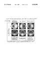
- FIGS. 6A, 6B, and 6C show contour maps of the difference between opposed surfaces obtained on the basis of values in the cases where the above-mentioned glass sheets A, B, and C are respectively employed as the reference plates, while the sample surface of a sample plate D is measured by the above-mentioned Fizeau interferometer.
- FIG. 6A shows the difference A+D between the reference surface of the glass sheet A and the sample surface of the sample plate D
- FIG. 6B shows the difference B+D between the reference surface of the glass sheet B and the sample surface of the sample plate D
- FIG. 6C shows the difference C+D between the reference surface of the glass sheet C and the sample surface of the sample plate D.
- FIGS. 6A', 6B', and 6C' show contour maps of forms in which the approximate forms of the reference surfaces of the corresponding glass reference plates are subtracted from the differences (A+D, B+D, C+D) respectively indicated by FIGS. 6A, 6B, and 6C.
- FIG. 6A' shows the sample surface form of the sample plate D in which the reference surface form of the glass sheet A is subtracted from the above-mentioned A+D
- FIG. 6B' shows the sample surface form of the sample plate D in which the reference surface form of the glass sheet B is subtracted from the above-mentioned B+D
- FIG. 6C' shows the sample surface form of the sample plate D in which the reference surface form of the glass sheet C is subtracted from the above-mentioned C+D.
Landscapes
- Physics & Mathematics (AREA)
- General Physics & Mathematics (AREA)
- Instruments For Measurement Of Length By Optical Means (AREA)
- Length Measuring Devices By Optical Means (AREA)
Applications Claiming Priority (4)
| Application Number | Priority Date | Filing Date | Title |
|---|---|---|---|
| JP9521197 | 1997-03-28 | ||
| JP9-095211 | 1997-03-28 | ||
| JP10-057461 | 1998-02-23 | ||
| JP05746198A JP4052489B2 (ja) | 1997-03-28 | 1998-02-23 | 平面形状測定解析方法 |
Publications (1)
| Publication Number | Publication Date |
|---|---|
| US6018990A true US6018990A (en) | 2000-02-01 |
Family
ID=26398512
Family Applications (1)
| Application Number | Title | Priority Date | Filing Date |
|---|---|---|---|
| US09/030,934 Expired - Lifetime US6018990A (en) | 1997-03-28 | 1998-02-26 | Flatness measuring and analyzing method |
Country Status (3)
| Country | Link |
|---|---|
| US (1) | US6018990A (ja) |
| JP (1) | JP4052489B2 (ja) |
| DE (1) | DE19810811B4 (ja) |
Cited By (9)
| Publication number | Priority date | Publication date | Assignee | Title |
|---|---|---|---|---|
| US6226417B1 (en) * | 1997-08-04 | 2001-05-01 | Ricoh Company, Ltd. | Method and system for recognizing a rotated image pattern with reduced processing time and memory space |
| US20020006223A1 (en) * | 2000-05-19 | 2002-01-17 | Ricoh Company, Ltd. | Image detecting method, image detecting system, program, and recording medium for image detection |
| US6461778B1 (en) | 2000-12-11 | 2002-10-08 | Micron Technology, Inc. | In-line method of measuring effective three-leaf aberration coefficient of lithography projection systems |
| EP1390722A1 (en) * | 2001-05-07 | 2004-02-25 | ASML US, Inc. | Interferometric determination of three-dimensional refractive index distribution |
| EP1515115A2 (en) * | 2003-09-09 | 2005-03-16 | Mitutoyo Corporation | Form measuring device, form measuring method, form analysis device, form analysis program, and recording medium storing the program |
| US20060066874A1 (en) * | 2004-09-24 | 2006-03-30 | Fujinon Corporation | Light intensity ratio adjustment filter for an interferometer, interferometer, and light interference measurement method |
| US7610519B1 (en) * | 2006-03-03 | 2009-10-27 | Xilinx, Inc. | Vector generation for codes through symmetry |
| FR2978827A1 (fr) * | 2011-08-05 | 2013-02-08 | Commissariat Energie Atomique | Procede de mesure absolue de la planeite des surfaces d'elements optiques |
| CN107388996A (zh) * | 2017-09-08 | 2017-11-24 | 上海理工大学 | 一种参考面平面度检验方法 |
Families Citing this family (3)
| Publication number | Priority date | Publication date | Assignee | Title |
|---|---|---|---|---|
| US9121684B2 (en) * | 2012-01-17 | 2015-09-01 | Kla-Tencor Corporation | Method for reducing wafer shape and thickness measurement errors resulted from cavity shape changes |
| JP6280458B2 (ja) * | 2014-06-27 | 2018-02-14 | 株式会社キーエンス | 三次元形状測定装置、測定データ処理ユニット、測定データ処理方法、及びコンピュータプログラム |
| CN107121114B (zh) * | 2017-05-08 | 2019-05-07 | 中国科学院长春光学精密机械与物理研究所 | 基于功率谱的大口径平面镜低阶像差估计方法 |
Citations (5)
| Publication number | Priority date | Publication date | Assignee | Title |
|---|---|---|---|---|
| US3703097A (en) * | 1970-12-24 | 1972-11-21 | Kaiser Aluminium Chem Corp | Method and system for measuring sheet flatness |
| US5153844A (en) * | 1990-01-23 | 1992-10-06 | E. I. Du Pont De Nemours And Company | Method and apparatus for measuring surface flatness |
| US5220403A (en) * | 1991-03-11 | 1993-06-15 | International Business Machines Corporation | Apparatus and a method for high numerical aperture microscopic examination of materials |
| US5502566A (en) * | 1993-07-23 | 1996-03-26 | Wyko Corporation | Method and apparatus for absolute optical measurement of entire surfaces of flats |
| US5739906A (en) * | 1996-06-07 | 1998-04-14 | The United States Of America As Represented By The Secretary Of Commerce | Interferometric thickness variation test method for windows and silicon wafers using a diverging wavefront |
-
1998
- 1998-02-23 JP JP05746198A patent/JP4052489B2/ja not_active Expired - Fee Related
- 1998-02-26 US US09/030,934 patent/US6018990A/en not_active Expired - Lifetime
- 1998-03-12 DE DE19810811A patent/DE19810811B4/de not_active Expired - Fee Related
Patent Citations (5)
| Publication number | Priority date | Publication date | Assignee | Title |
|---|---|---|---|---|
| US3703097A (en) * | 1970-12-24 | 1972-11-21 | Kaiser Aluminium Chem Corp | Method and system for measuring sheet flatness |
| US5153844A (en) * | 1990-01-23 | 1992-10-06 | E. I. Du Pont De Nemours And Company | Method and apparatus for measuring surface flatness |
| US5220403A (en) * | 1991-03-11 | 1993-06-15 | International Business Machines Corporation | Apparatus and a method for high numerical aperture microscopic examination of materials |
| US5502566A (en) * | 1993-07-23 | 1996-03-26 | Wyko Corporation | Method and apparatus for absolute optical measurement of entire surfaces of flats |
| US5739906A (en) * | 1996-06-07 | 1998-04-14 | The United States Of America As Represented By The Secretary Of Commerce | Interferometric thickness variation test method for windows and silicon wafers using a diverging wavefront |
Cited By (20)
| Publication number | Priority date | Publication date | Assignee | Title |
|---|---|---|---|---|
| US6226417B1 (en) * | 1997-08-04 | 2001-05-01 | Ricoh Company, Ltd. | Method and system for recognizing a rotated image pattern with reduced processing time and memory space |
| US20020006223A1 (en) * | 2000-05-19 | 2002-01-17 | Ricoh Company, Ltd. | Image detecting method, image detecting system, program, and recording medium for image detection |
| US6862370B2 (en) | 2000-05-19 | 2005-03-01 | Ricoh Company, Ltd. | Image detecting method, image detecting system, program, and recording medium for image detection |
| US6461778B1 (en) | 2000-12-11 | 2002-10-08 | Micron Technology, Inc. | In-line method of measuring effective three-leaf aberration coefficient of lithography projection systems |
| EP1390722A1 (en) * | 2001-05-07 | 2004-02-25 | ASML US, Inc. | Interferometric determination of three-dimensional refractive index distribution |
| EP1390722A4 (en) * | 2001-05-07 | 2008-02-20 | Asml Holding Nv | INTERFERROMETRIC DETERMINATION OF THE THREE-DIMENSIONAL BREAKING INDEX DISTRIBUTION |
| US7188046B2 (en) | 2003-09-09 | 2007-03-06 | Mitutoyo Corporation | Form measuring device, form measuring method, form analysis device, form analysis program, and recording medium storing the program |
| EP1515115A3 (en) * | 2003-09-09 | 2005-04-13 | Mitutoyo Corporation | Form measuring device, form measuring method, form analysis device, form analysis program, and recording medium storing the program |
| US7483807B2 (en) | 2003-09-09 | 2009-01-27 | Mitutoyo Corporation | Form measuring device, form measuring method, form analysis device, form analysis program, and recording medium storing the program |
| EP1742018A3 (en) * | 2003-09-09 | 2007-02-21 | Mitutoyo Corporation | Form measuring device, form measuring method, form analysis device, form analysis program and recording medium storing the program |
| US20050065751A1 (en) * | 2003-09-09 | 2005-03-24 | Mitutoyo Corporation | Form measuring device, form measuring method, form analysis device, form analysis program, and recording medium storing the program |
| US20070112541A1 (en) * | 2003-09-09 | 2007-05-17 | Mitutoyo Corporation | Form measuring device, form measuring method, form analysis device, form analysis program, and recording medium storing the program |
| EP1515115A2 (en) * | 2003-09-09 | 2005-03-16 | Mitutoyo Corporation | Form measuring device, form measuring method, form analysis device, form analysis program, and recording medium storing the program |
| US7375825B2 (en) * | 2004-09-24 | 2008-05-20 | Fujinon Corporation | Light intensity ratio adjustment filter for an interferometer, interferometer, and light interference measurement method |
| US20060066874A1 (en) * | 2004-09-24 | 2006-03-30 | Fujinon Corporation | Light intensity ratio adjustment filter for an interferometer, interferometer, and light interference measurement method |
| US7610519B1 (en) * | 2006-03-03 | 2009-10-27 | Xilinx, Inc. | Vector generation for codes through symmetry |
| FR2978827A1 (fr) * | 2011-08-05 | 2013-02-08 | Commissariat Energie Atomique | Procede de mesure absolue de la planeite des surfaces d'elements optiques |
| WO2013020925A1 (fr) * | 2011-08-05 | 2013-02-14 | Commissariat A L'energie Atomique Et Aux Energies Alternatives | Procede de mesure absolue de la planeite des surfaces d'elements optiques |
| US9267789B2 (en) | 2011-08-05 | 2016-02-23 | Commissariat à l'énergie atomique et aux énergies alternatives | Method for the absolute measurement of the flatness of the surfaces of optical elements, using an interferometer and a three-flat method |
| CN107388996A (zh) * | 2017-09-08 | 2017-11-24 | 上海理工大学 | 一种参考面平面度检验方法 |
Also Published As
| Publication number | Publication date |
|---|---|
| JPH10325710A (ja) | 1998-12-08 |
| DE19810811A1 (de) | 1998-10-01 |
| DE19810811B4 (de) | 2004-04-15 |
| JP4052489B2 (ja) | 2008-02-27 |
Similar Documents
| Publication | Publication Date | Title |
|---|---|---|
| US6018990A (en) | Flatness measuring and analyzing method | |
| JP4732362B2 (ja) | 多軸計測システムの幾何学配置を較正するための方法 | |
| JPH02128101A (ja) | 座標測定装置のための検査体 | |
| KR20000068713A (ko) | 좌표 측정기의 측정 오차 보정 방법 | |
| CN113776463B (zh) | 一种回转角度误差的测量方法 | |
| CN106840045A (zh) | 一种自准直仪的精度检测装置及其检测方法 | |
| Flack | Measurement good practice guide No. 42 | |
| Selberg | Interferometer accuracy and precision | |
| Bryan et al. | Angle interferometer cross-axis errors | |
| Zhang et al. | Improving the accuracy of angle measurement in machine calibration | |
| US20030128360A1 (en) | Elllipsometer and precision auto-alignment method for incident angle of the ellipsometer without auxiliary equipment | |
| JP3589774B2 (ja) | 高精度平面の形状測定方法 | |
| CN109282759A (zh) | 一种汽车活塞表面粗糙度检测方法 | |
| Roithmeier | Measuring Strategies in Tactile Coordinate Metrology | |
| Han et al. | High-accuracy absolute flatness testing using a commercial interferometer | |
| JP2003035529A (ja) | 被検体表面の平坦度測定系の系続誤差測定方法、これを用いた平坦度測定方法、及び、装置 | |
| JPH08247739A (ja) | ロータリーエンコーダパターンの測定装置及び測定方法 | |
| Hakkarainen | Determination of radial and tangential distortion of reseau cameras with the Helsinki University of Technology horizontal goniometer | |
| SU1732148A1 (ru) | Способ контрол угла конуса | |
| Zschommler | Manufacture of Test Plates | |
| Beyer | IMETRICS TP200: a system for high accuracy 3D image metrology | |
| Thalmann | Intercomparison of parallelism measurements | |
| ORKING | Testing Procedures for Analytical Plotters | |
| RU2206870C1 (ru) | Способ определения угла стеклянного клина | |
| SU1190337A1 (ru) | Способ калибровки многогранных призм |
Legal Events
| Date | Code | Title | Description |
|---|---|---|---|
| AS | Assignment |
Owner name: FUJI PHOTO OPTICAL CO., LTD., JAPAN Free format text: ASSIGNMENT OF ASSIGNORS INTEREST;ASSIGNOR:UEKI, NOBUAKI;REEL/FRAME:009185/0571 Effective date: 19980223 |
|
| FEPP | Fee payment procedure |
Free format text: PAYOR NUMBER ASSIGNED (ORIGINAL EVENT CODE: ASPN); ENTITY STATUS OF PATENT OWNER: LARGE ENTITY |
|
| STCF | Information on status: patent grant |
Free format text: PATENTED CASE |
|
| FPAY | Fee payment |
Year of fee payment: 4 |
|
| FPAY | Fee payment |
Year of fee payment: 8 |
|
| FPAY | Fee payment |
Year of fee payment: 12 |