US5970592A - Godet for heating a running synthetic thread - Google Patents
Godet for heating a running synthetic thread Download PDFInfo
- Publication number
- US5970592A US5970592A US09/011,848 US1184898A US5970592A US 5970592 A US5970592 A US 5970592A US 1184898 A US1184898 A US 1184898A US 5970592 A US5970592 A US 5970592A
- Authority
- US
- United States
- Prior art keywords
- godet
- carriers
- jacket
- side walls
- coil support
- Prior art date
- Legal status (The legal status is an assumption and is not a legal conclusion. Google has not performed a legal analysis and makes no representation as to the accuracy of the status listed.)
- Expired - Fee Related
Links
Images


Classifications
-
- H—ELECTRICITY
- H05—ELECTRIC TECHNIQUES NOT OTHERWISE PROVIDED FOR
- H05B—ELECTRIC HEATING; ELECTRIC LIGHT SOURCES NOT OTHERWISE PROVIDED FOR; CIRCUIT ARRANGEMENTS FOR ELECTRIC LIGHT SOURCES, IN GENERAL
- H05B6/00—Heating by electric, magnetic or electromagnetic fields
- H05B6/02—Induction heating
- H05B6/10—Induction heating apparatus, other than furnaces, for specific applications
- H05B6/14—Tools, e.g. nozzles, rollers, calenders
- H05B6/145—Heated rollers
-
- D—TEXTILES; PAPER
- D02—YARNS; MECHANICAL FINISHING OF YARNS OR ROPES; WARPING OR BEAMING
- D02J—FINISHING OR DRESSING OF FILAMENTS, YARNS, THREADS, CORDS, ROPES OR THE LIKE
- D02J13/00—Heating or cooling the yarn, thread, cord, rope, or the like, not specific to any one of the processes provided for in this subclass
- D02J13/005—Heating or cooling the yarn, thread, cord, rope, or the like, not specific to any one of the processes provided for in this subclass by contact with at least one rotating roll
Definitions
- the invention relates to a godet for heating an advancing filament yarn.
- U.S. Pat. No. 3,508,024 describes a godet for heating an advancing yarn wherein the godet has more than two axially adjacent stationary primary windings and a magnetically conductive godet jacket.
- the jacket is supported for rotation in concentric relationship with the primary windings, and is inductively connected with the primary windings via a narrow radial clearance for generating secondary currents.
- the carrier of the primary windings is built up from several laminated transformer sheets, which are arranged perpendicular to the axis of a coil support.
- a trigger circuit operates each of the primary windings with an alternating current of adjustable frequency, the primary windings being included in an oscillation circuit, which is adapted to the adjusted frequency. Via corresponding power switches in cooperation with associated temperature controllers, the oscillation circuit can be connected or disconnected as a function of the temperature measured on the godet jacket.
- a similar godet is described in GB 989,349, wherein a primary winding is mounted on a circular carrier arranged in concentric relationship with a hollow cylindrical godet jacket.
- all flat transformer sheets of the carrier accommodating the primary windings are laminated on a coil support in axial direction.
- the laminated iron sheets are arranged such as to form annular air gaps radially concentric with the axis of rotation of the godet.
- a godet which has a plurality of annular U-shaped carriers mounted in an axially adjacent arrangement along a fixed tubular coil support so that the carriers lie between the coil support and the tubular wall of the yarn engaging jacket of the godet.
- the carriers comprise a bottom wall and opposite side walls, and the bottom wall of each carrier comprises a plurality of axially extending transformer sheets which radially overlie each other.
- the side walls of each of the carriers comprise a plurality of transformer sheets which extend radially and overlie each other in the axial direction.
- An induction coil is mounted coaxially within each of the annular carriers, such that when an alternating current is delivered to the induction coils a secondary current is induced in the tubular wall of the jacket to thereby heat the jacket.
- transformer sheets ensure an improved heating of the godet jacket, since the leakage field within the godet is considerably reduced.
- a further advantage lies in that it is possible to use commercially available cut strip cores for receiving the windings. This simplifies the process of manufacture and reduces the costs. A clearance formed between adjacent cut strip cores leads to only a very small leakage field, which has no influence on the generated power and, thus, on the temperature in the godet jacket.
- the surface configuration of the channel bottom above which the carrier is arranged on the coil support simplifies assembly.
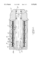
- FIG. 1 is a sectional view of an inductively heated godet
- FIG. 2 is an enlarged illustration of the channel bottom in region A of FIG. 1;
- FIG. 3 shows an embodiment of a carrier in region B of FIG. 1, the carrier comprising several transformer sheets stacked atop one another in U-shape;
- FIGS. 4A-4C illustrate further embodiments of a cut strip core in region B of FIG. 1, the cut strip core consisting of separate side walls and a separate channel bottom;
- FIG. 5 is a sectional view of the godet of FIG. 1, which shows the arrangement of a plurality of segmentlike cut strip cores over the circumference of the coil support;
- FIG. 6 is a sectional view of the godet of FIG. 1, and FIG. 4A, or 4B, or 4C, the Figure illustrating an annular separate side wall 3b;
- FIG. 7 is a sectional view similar to FIG. 6, the illustrated annular side wall 3b being made star-shaped;
- FIG. 8 is a partial view illustrating the mount of the cut strip core on the coil support.
- a plurality of channel-type carriers 3 are arranged axially on a coil support 5, each carrier accommodating a primary winding 1.
- a godet jacket 2 is secured by means of a cone arrangement 7 on a spindle 9 supported in two bearings 8.
- the bearings 8 are supported in a stationary housing 11.
- the godet jacket 2 has a substantially U-shaped cross section and at its front wall 2a a central opening, which is bounded by a substantially cylindrical, inward directed extension 13, which has an inside taper 7 adapted to a taper of spindle 9.
- Located at the free end of spindle 9 is a screw thread, which receives a nut 10 for securing godet jacket 2 on spindle 9.
- the coil support 5 extends in the form of a hollow cylinder along spindle 9 almost as far as the front wall 2a of godet jacket 2.
- Each carrier 3 comprises a channel bottom 3a and spaced-apart side walls 3b, so that a U-shaped annular space is formed which serves to receive primary winding 1.
- the side walls 3b extend radially almost as far as the inside surface of godet jacket 2.
- Two adjacent side walls 3b form each with the inner jacket surface a defined radial clearance 4 of a dimension corresponding to the side wall width.
- the primary windings 1 arranged on carriers 3 are separately controllable, so that a substantially constant temperature can be reached along the outer surface of godet jacket 2.
- the annular clearances 4 between side walls 3b and the inner surface of godet jacket 2, which is magnetically conductive, permit magnetic coupling of rotating godet jacket 2, so that a voltage is induced in the godet jacket, which results in a current flow.
- the current flow in the godet jacket along the circumference thereof results in heating caused by the electrical resistance of the godet material.
- purposeful connection and disconnection of the coil voltage permits adjustment of the temperature in the godet jacket.
- the transformer sheets are arranged in the channel bottom such that they overlie one another in radial direction.
- FIG. 2 Shown in FIG. 2 is a locally enlarged sectional view of channel bottom 3a, wherein the transformer sheets are stacked radially one atop the other in the region of the channel bottom.
- FIGS. 3 and 5 show a preferred embodiment, wherein the carriers 3 are formed such that the laminated transformer sheets are stacked into one another in U-shape to form so-called cut strip cores, i.e., the transformer sheets are laminated in radial direction and not--as is commonly known--in axial direction.
- Arranged over the circumference of the coil support 5 is a plurality of U-shaped cut strip cores 3 in the form of a plurality of segments.
- the advantage of using cut strip cores 3 lies in that the magnetic flux is shielded outward, in particular also toward coil support 5, so as to prevent a leakage field from escaping outward.
- the laminated transformer sheets are stacked into one another in U-shape. This facilitates in addition an optimal magnetic flux, which need not overcome boundary layers.
- thicker boundary layers are produced when using a high frequency of, for example, 2 kHz. These boundary layers lead to a considerable increase of resistance.
- the surface of channel bottom 3a, which mounts cut strip core 3 to coil support 5, is either substantially flat or adapted to the surface of support 5, and it contacts the surface of support 5. The winding extends in the circumferential direction.
- cut strip cores of adjacent primary windings may be offset from one another, so that gaps 14 form which are axially bounded by the width of side walls 3b.
- FIG. 4A Shown in FIG. 4A is a preferred embodiment, in which the carrier 3 consists of separate side walls 3b and a separate channel bottom 3a.
- the channel bottom 3a of carrier 3 is a hollow cylinder built up from a plurality of transformer sheets stacked in radial direction.
- the side walls 3b of carrier 3 comprise a plurality of axially stacked, annular transformer sheets.
- the leakage field extending between channel bottom 3a and side walls 3b is very small. As a result, there is no influence is on the generated current and, thus, on the temperature in godet jacket 2.
- FIG. 4B Shown in FIG. 4B is another preferred embodiment, in which the carrier 3 consists of separate side walls 3b and a separate bottom 3a.
- the bottom 3a of carrier 3 is a hollow cylinder built up from a plurality of transformer sheets stacked in radial direction.
- the side walls 3b of cut strip core 3 comprise a plurality of stacked annular transformer sheets.
- the axial leakage field extending between channel bottom 3a and side walls 3b is very small, which has no influence on the generated current and, thus, on the temperature in godet jacket 2.
- FIG. 4C Shown in FIG. 4C is another preferred embodiment, in which the carrier 3 consists of separate side walls 3b and a separate bottom 3a.
- the bottom 3a of cut strip core 3 is a hollow cylinder built up from a plurality of transformer sheets stacked in radial direction.
- the side walls 3b of carrier 3 comprise a plurality of stacked annular transformer sheets.
- the oblique leakage field extending between channel bottom 3a and side walls 3b is very small. As a result, there is no influence on the generated current and, thus, on the temperature in godet jacket 2.
- FIG. 6 illustrates a form of side wall 3b, which can be combined both with the arrangement of FIG. 4A and with the arrangement of FIG. 4B.
- the side wall 3b is stacked from a plurality of annular transformer sheets. This arrangement is especially low in losses, since the radial clearance 4 between side wall 3b and godet jacket 2 is made substantially constant in circumferential direction.
- FIG. 7 illustrates another form of side wall 3b, which can be combined both with the arrangement of FIG. 4A and with the arrangement of FIG. 4B.
- each annular transformer sheet has a star-shaped outer edge.
- the transformer sheets are axially stacked, so that the star-shaped outer edges are axially aligned one after the other.
- FIG. 8 illustrates a possible mount of carrier 3 to coil support 5, wherein each of carriers 3 which are made, for example, as cut strip cores, is attached by means of at least one screw 6 to coil support 5 of godet 2.
- U-shaped, laminated transformer sheets in particular cut strip cores, has furthermore the advantage that the thin metal sheets as are required for a high-frequency application can be used of a thickness as small as 0.01 mm. Since the depth of penetration of the magnetic flux decreases as frequency increases and, however, since performance of the magnetic flux occurs exclusively on the surface, such thin sheets are needed to keep power losses at a lower level.
Landscapes
- Physics & Mathematics (AREA)
- Electromagnetism (AREA)
- Engineering & Computer Science (AREA)
- Textile Engineering (AREA)
- General Induction Heating (AREA)
- Resistance Heating (AREA)
- Yarns And Mechanical Finishing Of Yarns Or Ropes (AREA)
Applications Claiming Priority (3)
| Application Number | Priority Date | Filing Date | Title |
|---|---|---|---|
| DE19624266 | 1996-06-18 | ||
| DE19624266 | 1996-06-18 | ||
| PCT/EP1997/003121 WO1997049265A1 (de) | 1996-06-18 | 1997-06-16 | Galette zum erhitzen eines laufenden synthetischen fadens |
Publications (1)
| Publication Number | Publication Date |
|---|---|
| US5970592A true US5970592A (en) | 1999-10-26 |
Family
ID=7797255
Family Applications (1)
| Application Number | Title | Priority Date | Filing Date |
|---|---|---|---|
| US09/011,848 Expired - Fee Related US5970592A (en) | 1996-06-18 | 1997-06-16 | Godet for heating a running synthetic thread |
Country Status (7)
| Country | Link |
|---|---|
| US (1) | US5970592A (de) |
| EP (1) | EP0845196B2 (de) |
| KR (1) | KR100446346B1 (de) |
| CN (1) | CN1135908C (de) |
| DE (1) | DE59708815D1 (de) |
| TW (1) | TW354339B (de) |
| WO (1) | WO1997049265A1 (de) |
Cited By (5)
| Publication number | Priority date | Publication date | Assignee | Title |
|---|---|---|---|---|
| US20040188422A1 (en) * | 2003-03-26 | 2004-09-30 | Kabushiki Kaisha Toshiba | Induction heat fixing device |
| US20040238531A1 (en) * | 2003-03-24 | 2004-12-02 | Kabushiki Kaisha Toshiba | Fixing device |
| US20060006978A1 (en) * | 2004-07-06 | 2006-01-12 | Klaus Meier | Inductor core for heatable godet roll |
| US20080099469A1 (en) * | 2006-04-24 | 2008-05-01 | Inductoheat, Inc. | Electric induction heat treatment of an end of tubular material |
| JP2008517164A (ja) * | 2004-10-14 | 2008-05-22 | ザウラー ゲゼルシャフト ミット ベシュレンクテル ハフツング ウント コンパニー コマンディートゲゼルシャフト | 糸をガイドし、加熱し、かつ搬送するためのゴデット |
Families Citing this family (2)
| Publication number | Priority date | Publication date | Assignee | Title |
|---|---|---|---|---|
| CN101431884B (zh) * | 2008-12-11 | 2013-03-20 | 马嘉惠 | 一种与射频聚焦加热装置配套的电磁屏蔽装置 |
| CN115198419B (zh) * | 2022-08-12 | 2023-09-26 | 昆山联滔电子有限公司 | 一种编织线热压机 |
Citations (17)
| Publication number | Priority date | Publication date | Assignee | Title |
|---|---|---|---|---|
| GB858855A (en) * | 1956-05-15 | 1961-01-18 | Wild Barfield Electr Furnaces | Induction heated rotary rollers |
| GB989349A (en) * | 1961-09-26 | 1965-04-14 | Tmm Research Ltd | Improvements in heating arrangements for textile processing machines |
| US3412229A (en) * | 1966-10-20 | 1968-11-19 | Cameron Brown Capital Corp | Electric heating means |
| US3448233A (en) * | 1967-09-26 | 1969-06-03 | Pillar Corp | Induction heating assembly |
| US3487187A (en) * | 1967-08-16 | 1969-12-30 | Barmag Barmer Maschf | Inductively heatable galette |
| US3508024A (en) * | 1968-06-17 | 1970-04-21 | Gen Electric | Dual inductance induction heater |
| GB1202816A (en) * | 1967-08-16 | 1970-08-19 | Barmag Barmer Maschf | Inductively heatable godet |
| US3529116A (en) * | 1964-11-21 | 1970-09-15 | Tokushu Denki Kk | Heating rotary drum apparatus having shaped flux pattern |
| US3562489A (en) * | 1968-10-24 | 1971-02-09 | Barmag Barmer Maschf | Heated godet |
| US3581060A (en) * | 1965-12-03 | 1971-05-25 | Barmag Barmer Maschf | Temperature control device in a heated galette |
| GB1319318A (en) * | 1970-07-01 | 1973-06-06 | Platt International Ltd | Inductively heatable roller having a temperature sensor |
| GB2162729A (en) * | 1984-07-30 | 1986-02-05 | Tokuden Kk | Roller with three-phase induction heating |
| EP0349829A2 (de) * | 1988-06-30 | 1990-01-10 | Maschinenfabrik Rieter Ag | Galette mit breitem Drehzahlbereich |
| US5159166A (en) * | 1988-06-30 | 1992-10-27 | Rieter Machine Works, Ltd. | Drawroll unit |
| US5362945A (en) * | 1991-04-27 | 1994-11-08 | Barmag Ag | Godet for heating an advancing yarn |
| US5421070A (en) * | 1992-12-03 | 1995-06-06 | Barmag Ag | Godet for guiding and heating an advancing yarn |
| US5665043A (en) * | 1994-11-10 | 1997-09-09 | Barmag Ag | Godet for heating and advancing yarns |
Family Cites Families (1)
| Publication number | Priority date | Publication date | Assignee | Title |
|---|---|---|---|---|
| US3562472A (en) † | 1969-08-20 | 1971-02-09 | Gen Electric | Induction heater for rotating godet |
-
1997
- 1997-06-16 CN CNB971907315A patent/CN1135908C/zh not_active Expired - Fee Related
- 1997-06-16 WO PCT/EP1997/003121 patent/WO1997049265A1/de not_active Ceased
- 1997-06-16 KR KR10-1998-0700959A patent/KR100446346B1/ko not_active Expired - Fee Related
- 1997-06-16 EP EP97928210A patent/EP0845196B2/de not_active Expired - Lifetime
- 1997-06-16 DE DE59708815T patent/DE59708815D1/de not_active Expired - Lifetime
- 1997-06-16 US US09/011,848 patent/US5970592A/en not_active Expired - Fee Related
- 1997-06-18 TW TW086108517A patent/TW354339B/zh not_active IP Right Cessation
Patent Citations (19)
| Publication number | Priority date | Publication date | Assignee | Title |
|---|---|---|---|---|
| GB858855A (en) * | 1956-05-15 | 1961-01-18 | Wild Barfield Electr Furnaces | Induction heated rotary rollers |
| GB989349A (en) * | 1961-09-26 | 1965-04-14 | Tmm Research Ltd | Improvements in heating arrangements for textile processing machines |
| US3529116A (en) * | 1964-11-21 | 1970-09-15 | Tokushu Denki Kk | Heating rotary drum apparatus having shaped flux pattern |
| DE1565149A1 (de) * | 1964-11-21 | 1970-10-01 | ||
| US3581060A (en) * | 1965-12-03 | 1971-05-25 | Barmag Barmer Maschf | Temperature control device in a heated galette |
| US3412229A (en) * | 1966-10-20 | 1968-11-19 | Cameron Brown Capital Corp | Electric heating means |
| US3487187A (en) * | 1967-08-16 | 1969-12-30 | Barmag Barmer Maschf | Inductively heatable galette |
| GB1202816A (en) * | 1967-08-16 | 1970-08-19 | Barmag Barmer Maschf | Inductively heatable godet |
| US3448233A (en) * | 1967-09-26 | 1969-06-03 | Pillar Corp | Induction heating assembly |
| US3508024A (en) * | 1968-06-17 | 1970-04-21 | Gen Electric | Dual inductance induction heater |
| US3562489A (en) * | 1968-10-24 | 1971-02-09 | Barmag Barmer Maschf | Heated godet |
| GB1319318A (en) * | 1970-07-01 | 1973-06-06 | Platt International Ltd | Inductively heatable roller having a temperature sensor |
| GB2162729A (en) * | 1984-07-30 | 1986-02-05 | Tokuden Kk | Roller with three-phase induction heating |
| US4647744A (en) * | 1984-07-30 | 1987-03-03 | Tokuden Co., Ltd. | Rotating heating roller of the type having a three phase circumferentially laminated leg core |
| EP0349829A2 (de) * | 1988-06-30 | 1990-01-10 | Maschinenfabrik Rieter Ag | Galette mit breitem Drehzahlbereich |
| US5159166A (en) * | 1988-06-30 | 1992-10-27 | Rieter Machine Works, Ltd. | Drawroll unit |
| US5362945A (en) * | 1991-04-27 | 1994-11-08 | Barmag Ag | Godet for heating an advancing yarn |
| US5421070A (en) * | 1992-12-03 | 1995-06-06 | Barmag Ag | Godet for guiding and heating an advancing yarn |
| US5665043A (en) * | 1994-11-10 | 1997-09-09 | Barmag Ag | Godet for heating and advancing yarns |
Cited By (17)
| Publication number | Priority date | Publication date | Assignee | Title |
|---|---|---|---|---|
| US20040238531A1 (en) * | 2003-03-24 | 2004-12-02 | Kabushiki Kaisha Toshiba | Fixing device |
| US7335863B2 (en) | 2003-03-24 | 2008-02-26 | Kabushiki Kaisha Toshiba | Fixing device |
| US7105784B2 (en) * | 2003-03-24 | 2006-09-12 | Kabushiki Kaisha Toshiba | Fixing device |
| US20060289485A1 (en) * | 2003-03-24 | 2006-12-28 | Kabushiki Kaisha Toshiba | Fixing device |
| US20040188422A1 (en) * | 2003-03-26 | 2004-09-30 | Kabushiki Kaisha Toshiba | Induction heat fixing device |
| US20050040159A1 (en) * | 2003-03-26 | 2005-02-24 | Kabushiki Kaisha Toshiba | Induction heat fixing device |
| US6861627B2 (en) * | 2003-03-26 | 2005-03-01 | Kabushiki Kaisha Toshiba | Induction heat fixing device |
| US7161123B2 (en) | 2003-03-26 | 2007-01-09 | Kabushiki Kaisha Toshiba | Induction heat fixing device |
| US7170386B2 (en) * | 2004-07-06 | 2007-01-30 | Schärer Schweiter Mettler Ag | Inductor core for heatable godet roll |
| US20060006978A1 (en) * | 2004-07-06 | 2006-01-12 | Klaus Meier | Inductor core for heatable godet roll |
| CN100518417C (zh) * | 2004-07-06 | 2009-07-22 | Ssm萨罗瑞士麦特雷有限公司 | 用于可加热导丝辊的感应芯 |
| JP2008517164A (ja) * | 2004-10-14 | 2008-05-22 | ザウラー ゲゼルシャフト ミット ベシュレンクテル ハフツング ウント コンパニー コマンディートゲゼルシャフト | 糸をガイドし、加熱し、かつ搬送するためのゴデット |
| US20080099469A1 (en) * | 2006-04-24 | 2008-05-01 | Inductoheat, Inc. | Electric induction heat treatment of an end of tubular material |
| US20080099468A1 (en) * | 2006-04-24 | 2008-05-01 | Inductoheat, Inc. | Electric induction heat treatment of an end of tubular material |
| WO2007127566A3 (en) * | 2006-04-24 | 2008-07-24 | Inductoheat Inc | Electric induction heat treatment of an end of tubular material |
| RU2428821C2 (ru) * | 2006-04-24 | 2011-09-10 | Индактохит, Инк. | Электроиндукционная термическая обработка конца трубчатого материала |
| US8895906B2 (en) | 2006-04-24 | 2014-11-25 | Inductoheat, Inc. | Electric induction heat treatment of an end of tubular material |
Also Published As
| Publication number | Publication date |
|---|---|
| KR100446346B1 (ko) | 2004-10-14 |
| WO1997049265A1 (de) | 1997-12-24 |
| EP0845196A1 (de) | 1998-06-03 |
| CN1196864A (zh) | 1998-10-21 |
| EP0845196B2 (de) | 2011-07-06 |
| KR19990036291A (ko) | 1999-05-25 |
| EP0845196B1 (de) | 2002-11-27 |
| CN1135908C (zh) | 2004-01-21 |
| TW354339B (en) | 1999-03-11 |
| DE59708815D1 (de) | 2003-01-09 |
Similar Documents
| Publication | Publication Date | Title |
|---|---|---|
| US4385251A (en) | Flux shield for an inductor-alternator machine | |
| US4005302A (en) | Inductively heated drawroll | |
| EP0364171B1 (de) | Hochfrequenzheizgerät mit einer frequenzumwandelnden Speisung | |
| US3200230A (en) | Apparatus for the heating of travelling thread or tape-shaped products on a transport roller | |
| JP3439705B2 (ja) | 加熱ロール用誘導加熱装置 | |
| US5970592A (en) | Godet for heating a running synthetic thread | |
| US3772492A (en) | Induction heater for fiber processing roll | |
| US3701873A (en) | Inductively heated godet | |
| US4647744A (en) | Rotating heating roller of the type having a three phase circumferentially laminated leg core | |
| EP3026796B1 (de) | Elektrische drehfeldmaschine | |
| US3487187A (en) | Inductively heatable galette | |
| EP3753378B1 (de) | Induktor für elektromagnetische induktionsheizung zum plastifizieren von zylindern | |
| US7271370B2 (en) | Yarn guiding godet with magnetic bearings | |
| US4021764A (en) | Sheet-wound transformer coils with reduced edge heating | |
| GB2227823A (en) | Drying cylinder | |
| JP4221227B2 (ja) | ゴデット | |
| JP3769299B2 (ja) | 超伝導巻線を備えた変圧器 | |
| US7170386B2 (en) | Inductor core for heatable godet roll | |
| JPH07194093A (ja) | 超電導回転電機の固定子 | |
| JPH09161963A (ja) | ローラの加熱装置 | |
| CA1079823A (en) | Sheet-wound transformer coils with reduced edge heating | |
| JP2001215823A (ja) | 定着装置 | |
| KR100767480B1 (ko) | 편지식(片持式) 히팅 롤 | |
| JPS5933786A (ja) | 高周波誘導加熱ロ−ラ | |
| SU705698A1 (ru) | Индуктор дл нагрева деталей |
Legal Events
| Date | Code | Title | Description |
|---|---|---|---|
| AS | Assignment |
Owner name: BARMAG AG, GERMANY Free format text: ASSIGNMENT OF ASSIGNORS INTEREST;ASSIGNORS:FELDHOFF, RALF;TIETMEYER, STEFAN;VOSS, RAINALD;REEL/FRAME:009482/0337 Effective date: 19980210 |
|
| FEPP | Fee payment procedure |
Free format text: PAYOR NUMBER ASSIGNED (ORIGINAL EVENT CODE: ASPN); ENTITY STATUS OF PATENT OWNER: LARGE ENTITY |
|
| FPAY | Fee payment |
Year of fee payment: 4 |
|
| REMI | Maintenance fee reminder mailed | ||
| FPAY | Fee payment |
Year of fee payment: 8 |
|
| REMI | Maintenance fee reminder mailed | ||
| LAPS | Lapse for failure to pay maintenance fees | ||
| STCH | Information on status: patent discontinuation |
Free format text: PATENT EXPIRED DUE TO NONPAYMENT OF MAINTENANCE FEES UNDER 37 CFR 1.362 |
|
| FP | Lapsed due to failure to pay maintenance fee |
Effective date: 20111026 |