US588564A - Razor-guard - Google Patents
Razor-guard Download PDFInfo
- Publication number
- US588564A US588564A US588564DA US588564A US 588564 A US588564 A US 588564A US 588564D A US588564D A US 588564DA US 588564 A US588564 A US 588564A
- Authority
- US
- United States
- Prior art keywords
- blade
- razor
- guard
- bar
- arm
- Prior art date
- Legal status (The legal status is an assumption and is not a legal conclusion. Google has not performed a legal analysis and makes no representation as to the accuracy of the status listed.)
- Expired - Lifetime
Links
Images
Classifications
-
- H—ELECTRICITY
- H02—GENERATION; CONVERSION OR DISTRIBUTION OF ELECTRIC POWER
- H02J—ELECTRIC POWER NETWORKS; CIRCUIT ARRANGEMENTS OR SYSTEMS FOR SUPPLYING OR DISTRIBUTING ELECTRIC POWER; SYSTEMS FOR STORING ELECTRIC ENERGY
- H02J1/00—Circuit arrangements for DC mains or DC distribution networks
- H02J1/10—Parallel operation of DC sources
- H02J1/12—Parallel operation of DC sources having power converters with further DC sources without power converters
Definitions
- the object of the invention is to provide a new and improvedrazor-guard-arranged for convenient attachment to and adjustment on either side of the razor-blade to render selfshaving easy and safe.
- the invention consists principally of a guard-bar adapted to engage one side of the blade, a clamping device adapted to engage the other side of the blade, and a fastening device for connecting the bar and arm.
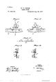
- Figure 1 is a rear elevation of the improvement as applied.
- Fig. 2 is a front elevation of the same.
- Fig. 3 is an end view of the same.
- Fig. t is a transverse section of the same on the line 4 at of Fig. 1, and
- Fig. 5 is a ed to rest on one side of the razor-blade B, so
- the bar A By having the arm A slotted it is evident that on loosening the screw D the bar A may be readily adjusted up or down to bring the lower edge of the bar A closer toor'farthe'r from the cutting edge of the blade B to enable-the operator to set the said bar for convenient shaving, as desired, by the user of the razor.
- the slotted arm A also allows the clamping device to be set at any distance from the bar, thus rendering it immaterial whether the distance from the back to the edge of the blade is long or short, and consequent-1y the device can be readily applied to large or small razors.
- the razor-guard can be readily detached from the blade for cleaning purposes whenever desired.
- the device is very simple and durable in construction and can be cheaply manufactured and readily applied to any style of razor.
- a razor-guard comprising a guard-bar arrangedtoengage one side of the blade and provided with a slotted vertical arm extending above the blade, a forked clamping de vice bearing against that side of said vertical arm above the razor-blade which is opposite the side adjacent said blade andhaving downwardlyextending members curved around said vertical arm to engagement with the opposite side of said blade, and a clampvertical arm and engaging the other side of the razor-blade, and a clamping-screw having its shank inserted through the slot in the vertical arm and screwing in the said clamping device, whereby the guard-bar may be adj nsted vertically and transversely, as set forth.
Landscapes
- Engineering & Computer Science (AREA)
- Power Engineering (AREA)
- Breeding Of Plants And Reproduction By Means Of Culturing (AREA)
Description
(No Model.)
T. FISHER. RAZOR GUARD.
No; 588,564. Patented Aug. -24, 1897.
' [NI/EN I? WIT/V5885 ATTORNEYS.
r DRRIS PETEI (5 co, Panto-um... wmnmemu. n. c.
PATENT FFICE.
HOWELL T. FISHER, OF POTTSVILLE, PENNSYLVANIA.
RAZOR- GUARD.
SPECIFICATION forming part of Letters Patent No. 588,564, dated August 24, 1897.
Application filed November 28, 1896- Serial No. 613,733. (No model.) I
To all whcm it may concern.-
Be it known that I, HOWELL T. FISHER, of Pottsville, in the county of Schuylkill and State of Pennsylvania, have invented a new and Improved Razor-Guard, of which the following is a full, clear, and exact description.
The object of the invention is to provide a new and improvedrazor-guard-arranged for convenient attachment to and adjustment on either side of the razor-blade to render selfshaving easy and safe.
The invention consists principally of a guard-bar adapted to engage one side of the blade, a clamping device adapted to engage the other side of the blade, and a fastening device for connecting the bar and arm.
The invention also consists of certain parts and details and combinations of the same, as will be fully described hereinafter and then pointed out in the claims. I
Reference is to be had to the accompanying drawings, forming a part of this specification, in which similar characters of reference indicate corresponding parts in all the figures.
Figure 1 is a rear elevation of the improvement as applied. Fig. 2 is a front elevation of the same. Fig. 3 is an end view of the same. Fig. t is a transverse section of the same on the line 4 at of Fig. 1, and Fig. 5 is a ed to rest on one side of the razor-blade B, so
as to'hold the inner face of the bar A a suitable distance from the adjacent face of the blade 13, as is plainly indicated in Figs. 3 and 4.
From the bar A extends upward a slotted arm A resting against the edge of the back of the blade and projecting through the forked clamping deviceQhaVing the free ends 0 of its fork members curved to engage and rest on that side of the razor-blade B opposite to the one engaged by the lugs A.
In the-clampin g device 0 screws a clam pin gscrew D, the shank of which passes through the slot in the arm A and has its shoulder D resting on the arm A so that' by screwing up the screw D the clamping device 0 and the arm A of the bar A are securely fastened together to hold the entire razor-guard in proper position on the blade B.
By having the arm A slotted it is evident that on loosening the screw D the bar A may be readily adjusted up or down to bring the lower edge of the bar A closer toor'farthe'r from the cutting edge of the blade B to enable-the operator to set the said bar for convenient shaving, as desired, by the user of the razor. The slotted arm A also allows the clamping device to be set at any distance from the bar, thus rendering it immaterial whether the distance from the back to the edge of the blade is long or short, and consequent-1y the device can be readily applied to large or small razors.
The razor-guard can be readily detached from the blade for cleaning purposes whenever desired. I
The device is very simple and durable in construction and can be cheaply manufactured and readily applied to any style of razor.
Having thus described my invention, I claim as new and desire to secure by Letters Patent- 1. The combination with a razor-blade, of a guard consisting of a guard-bar engaging one side of said blade and formed with a slotted arm extended upwardly therefrom above the said blade, a clamping device engaging said arm above the blade and the opposite side of said blade, and a clamping-screw bearing against said'arm and having its shank inserted through the slot therein and screwing in said clamping device, whereby the lower edge of said bar may be adjusted vertically and transversely in relation to its distance from the cutting edge of the razorblade, as set forth.
2. A razor-guard comprising a guard-bar arrangedtoengage one side of the blade and provided with a slotted vertical arm extending above the blade, a forked clamping de vice bearing against that side of said vertical arm above the razor-blade which is opposite the side adjacent said blade andhaving downwardlyextending members curved around said vertical arm to engagement with the opposite side of said blade, and a clampvertical arm and engaging the other side of the razor-blade, and a clamping-screw having its shank inserted through the slot in the vertical arm and screwing in the said clamping device, whereby the guard-bar may be adj nsted vertically and transversely, as set forth.
' HOWELL T. FISHER. Vitnesses:
R. J. MOGAFFREY,
GAETANO FERRARO.
Publications (1)
| Publication Number | Publication Date |
|---|---|
| US588564A true US588564A (en) | 1897-08-24 |
Family
ID=2657229
Family Applications (1)
| Application Number | Title | Priority Date | Filing Date |
|---|---|---|---|
| US588564D Expired - Lifetime US588564A (en) | Razor-guard |
Country Status (1)
| Country | Link |
|---|---|
| US (1) | US588564A (en) |
Cited By (1)
| Publication number | Priority date | Publication date | Assignee | Title |
|---|---|---|---|---|
| US20050001523A1 (en) * | 2003-05-13 | 2005-01-06 | Ken Wiklund | Drawer closing mechanism |
-
0
- US US588564D patent/US588564A/en not_active Expired - Lifetime
Cited By (2)
| Publication number | Priority date | Publication date | Assignee | Title |
|---|---|---|---|---|
| US20050001523A1 (en) * | 2003-05-13 | 2005-01-06 | Ken Wiklund | Drawer closing mechanism |
| US7077488B2 (en) * | 2003-05-13 | 2006-07-18 | Grass America Inc. | Drawer closing mechanism |
Similar Documents
| Publication | Publication Date | Title |
|---|---|---|
| US588564A (en) | Razor-guard | |
| US552077A (en) | David henry wagner | |
| US951456A (en) | Safety-razor. | |
| US332030A (en) | young | |
| US991998A (en) | Safety-razor. | |
| US1331243A (en) | Razor-blade holder | |
| US1216381A (en) | Razor. | |
| US775379A (en) | Safety-razor. | |
| US673886A (en) | Razor-guard. | |
| US311067A (en) | Razor-guard | |
| US380387A (en) | Razor | |
| US483684A (en) | William l | |
| US256979A (en) | Extension-bit and washer-cutter | |
| US824821A (en) | Gage. | |
| US980027A (en) | Razor attachment. | |
| US794798A (en) | Safety-razor-blade holder. | |
| US497797A (en) | Pipe-tongs | |
| US512125A (en) | Ernst scharff | |
| US315708A (en) | Halmb | |
| US841729A (en) | Safety-razor. | |
| US570598A (en) | Morris s | |
| US1155663A (en) | Ice-shaver. | |
| US1046975A (en) | Pencil marking-gage. | |
| US322040A (en) | Gage for drawing-knives | |
| US560493A (en) | Ruth ethelinda gibbs |