US5841193A - Single chip modules, repairable multichip modules, and methods of fabrication thereof - Google Patents
Single chip modules, repairable multichip modules, and methods of fabrication thereof Download PDFInfo
- Publication number
- US5841193A US5841193A US08/650,628 US65062896A US5841193A US 5841193 A US5841193 A US 5841193A US 65062896 A US65062896 A US 65062896A US 5841193 A US5841193 A US 5841193A
- Authority
- US
- United States
- Prior art keywords
- chips
- chip
- structural material
- integrated circuit
- planar
- Prior art date
- Legal status (The legal status is an assumption and is not a legal conclusion. Google has not performed a legal analysis and makes no representation as to the accuracy of the status listed.)
- Expired - Lifetime
Links
Images


Classifications
-
- H—ELECTRICITY
- H10—SEMICONDUCTOR DEVICES; ELECTRIC SOLID-STATE DEVICES NOT OTHERWISE PROVIDED FOR
- H10W—GENERIC PACKAGES, INTERCONNECTIONS, CONNECTORS OR OTHER CONSTRUCTIONAL DETAILS OF DEVICES COVERED BY CLASS H10
- H10W70/00—Package substrates; Interposers; Redistribution layers [RDL]
- H10W70/01—Manufacture or treatment
- H10W70/05—Manufacture or treatment of insulating or insulated package substrates, or of interposers, or of redistribution layers
- H10W70/08—Manufacture or treatment of insulating or insulated package substrates, or of interposers, or of redistribution layers by depositing layers on the chip or wafer, e.g. "chip-first" RDLs
- H10W70/09—Manufacture or treatment of insulating or insulated package substrates, or of interposers, or of redistribution layers by depositing layers on the chip or wafer, e.g. "chip-first" RDLs extending onto an encapsulation that laterally surrounds the chip or wafer, e.g. fan-out wafer level package [FOWLP] RDLs
-
- H—ELECTRICITY
- H10—SEMICONDUCTOR DEVICES; ELECTRIC SOLID-STATE DEVICES NOT OTHERWISE PROVIDED FOR
- H10W—GENERIC PACKAGES, INTERCONNECTIONS, CONNECTORS OR OTHER CONSTRUCTIONAL DETAILS OF DEVICES COVERED BY CLASS H10
- H10W70/00—Package substrates; Interposers; Redistribution layers [RDL]
- H10W70/60—Insulating or insulated package substrates; Interposers; Redistribution layers
- H10W70/611—Insulating or insulated package substrates; Interposers; Redistribution layers for connecting multiple chips together
- H10W70/614—Insulating or insulated package substrates; Interposers; Redistribution layers for connecting multiple chips together the multiple chips being integrally enclosed
-
- H—ELECTRICITY
- H10—SEMICONDUCTOR DEVICES; ELECTRIC SOLID-STATE DEVICES NOT OTHERWISE PROVIDED FOR
- H10W—GENERIC PACKAGES, INTERCONNECTIONS, CONNECTORS OR OTHER CONSTRUCTIONAL DETAILS OF DEVICES COVERED BY CLASS H10
- H10W90/00—Package configurations
-
- H—ELECTRICITY
- H10—SEMICONDUCTOR DEVICES; ELECTRIC SOLID-STATE DEVICES NOT OTHERWISE PROVIDED FOR
- H10P—GENERIC PROCESSES OR APPARATUS FOR THE MANUFACTURE OR TREATMENT OF DEVICES COVERED BY CLASS H10
- H10P72/00—Handling or holding of wafers, substrates or devices during manufacture or treatment thereof
- H10P72/70—Handling or holding of wafers, substrates or devices during manufacture or treatment thereof for supporting or gripping
- H10P72/74—Handling or holding of wafers, substrates or devices during manufacture or treatment thereof for supporting or gripping using temporarily an auxiliary support
- H10P72/7424—Handling or holding of wafers, substrates or devices during manufacture or treatment thereof for supporting or gripping using temporarily an auxiliary support used as a support during the manufacture of self-supporting substrates
-
- H—ELECTRICITY
- H10—SEMICONDUCTOR DEVICES; ELECTRIC SOLID-STATE DEVICES NOT OTHERWISE PROVIDED FOR
- H10P—GENERIC PROCESSES OR APPARATUS FOR THE MANUFACTURE OR TREATMENT OF DEVICES COVERED BY CLASS H10
- H10P72/00—Handling or holding of wafers, substrates or devices during manufacture or treatment thereof
- H10P72/70—Handling or holding of wafers, substrates or devices during manufacture or treatment thereof for supporting or gripping
- H10P72/74—Handling or holding of wafers, substrates or devices during manufacture or treatment thereof for supporting or gripping using temporarily an auxiliary support
- H10P72/743—Handling or holding of wafers, substrates or devices during manufacture or treatment thereof for supporting or gripping using temporarily an auxiliary support used as a support during manufacture of interconnect decals or build up layers
-
- H—ELECTRICITY
- H10—SEMICONDUCTOR DEVICES; ELECTRIC SOLID-STATE DEVICES NOT OTHERWISE PROVIDED FOR
- H10P—GENERIC PROCESSES OR APPARATUS FOR THE MANUFACTURE OR TREATMENT OF DEVICES COVERED BY CLASS H10
- H10P72/00—Handling or holding of wafers, substrates or devices during manufacture or treatment thereof
- H10P72/70—Handling or holding of wafers, substrates or devices during manufacture or treatment thereof for supporting or gripping
- H10P72/74—Handling or holding of wafers, substrates or devices during manufacture or treatment thereof for supporting or gripping using temporarily an auxiliary support
- H10P72/7432—Handling or holding of wafers, substrates or devices during manufacture or treatment thereof for supporting or gripping using temporarily an auxiliary support used in a transfer process involving transfer directly from an origin substrate to a target substrate without use of an intermediate handle substrate
-
- H—ELECTRICITY
- H10—SEMICONDUCTOR DEVICES; ELECTRIC SOLID-STATE DEVICES NOT OTHERWISE PROVIDED FOR
- H10W—GENERIC PACKAGES, INTERCONNECTIONS, CONNECTORS OR OTHER CONSTRUCTIONAL DETAILS OF DEVICES COVERED BY CLASS H10
- H10W70/00—Package substrates; Interposers; Redistribution layers [RDL]
- H10W70/60—Insulating or insulated package substrates; Interposers; Redistribution layers
-
- H—ELECTRICITY
- H10—SEMICONDUCTOR DEVICES; ELECTRIC SOLID-STATE DEVICES NOT OTHERWISE PROVIDED FOR
- H10W—GENERIC PACKAGES, INTERCONNECTIONS, CONNECTORS OR OTHER CONSTRUCTIONAL DETAILS OF DEVICES COVERED BY CLASS H10
- H10W72/00—Interconnections or connectors in packages
- H10W72/851—Dispositions of multiple connectors or interconnections
- H10W72/874—On different surfaces
-
- H—ELECTRICITY
- H10—SEMICONDUCTOR DEVICES; ELECTRIC SOLID-STATE DEVICES NOT OTHERWISE PROVIDED FOR
- H10W—GENERIC PACKAGES, INTERCONNECTIONS, CONNECTORS OR OTHER CONSTRUCTIONAL DETAILS OF DEVICES COVERED BY CLASS H10
- H10W72/00—Interconnections or connectors in packages
- H10W72/90—Bond pads, in general
- H10W72/941—Dispositions of bond pads
- H10W72/9413—Dispositions of bond pads on encapsulations
-
- H—ELECTRICITY
- H10—SEMICONDUCTOR DEVICES; ELECTRIC SOLID-STATE DEVICES NOT OTHERWISE PROVIDED FOR
- H10W—GENERIC PACKAGES, INTERCONNECTIONS, CONNECTORS OR OTHER CONSTRUCTIONAL DETAILS OF DEVICES COVERED BY CLASS H10
- H10W72/00—Interconnections or connectors in packages
- H10W72/90—Bond pads, in general
- H10W72/941—Dispositions of bond pads
- H10W72/9415—Dispositions of bond pads relative to the surface, e.g. recessed, protruding
-
- H—ELECTRICITY
- H10—SEMICONDUCTOR DEVICES; ELECTRIC SOLID-STATE DEVICES NOT OTHERWISE PROVIDED FOR
- H10W—GENERIC PACKAGES, INTERCONNECTIONS, CONNECTORS OR OTHER CONSTRUCTIONAL DETAILS OF DEVICES COVERED BY CLASS H10
- H10W74/00—Encapsulations, e.g. protective coatings
- H10W74/10—Encapsulations, e.g. protective coatings characterised by their shape or disposition
- H10W74/131—Encapsulations, e.g. protective coatings characterised by their shape or disposition the semiconductor body being only partially enclosed
- H10W74/142—Encapsulations, e.g. protective coatings characterised by their shape or disposition the semiconductor body being only partially enclosed the encapsulations exposing the passive side of the semiconductor body
-
- H—ELECTRICITY
- H10—SEMICONDUCTOR DEVICES; ELECTRIC SOLID-STATE DEVICES NOT OTHERWISE PROVIDED FOR
- H10W—GENERIC PACKAGES, INTERCONNECTIONS, CONNECTORS OR OTHER CONSTRUCTIONAL DETAILS OF DEVICES COVERED BY CLASS H10
- H10W90/00—Package configurations
- H10W90/10—Configurations of laterally-adjacent chips
-
- Y—GENERAL TAGGING OF NEW TECHNOLOGICAL DEVELOPMENTS; GENERAL TAGGING OF CROSS-SECTIONAL TECHNOLOGIES SPANNING OVER SEVERAL SECTIONS OF THE IPC; TECHNICAL SUBJECTS COVERED BY FORMER USPC CROSS-REFERENCE ART COLLECTIONS [XRACs] AND DIGESTS
- Y10—TECHNICAL SUBJECTS COVERED BY FORMER USPC
- Y10S—TECHNICAL SUBJECTS COVERED BY FORMER USPC CROSS-REFERENCE ART COLLECTIONS [XRACs] AND DIGESTS
- Y10S438/00—Semiconductor device manufacturing: process
- Y10S438/928—Front and rear surface processing
Definitions
- the present invention is generally related to multichip and single chip modules, and in particular, to the broad category of chips first fabrication of extremely thin multichip and single chip modules, as well as to repairable multichip modules.
- Process speed is limited by the fact that individual packages have loading capacitance and inductance associated with their relatively long pins and by the large size of conductor runs in the packages relative to the size of the conductors of a bare IC chip.
- the problem of providing electronic packaging and interconnect which provides maximum performance has become a significant challenge.
- Interconnect density is also increasing. As computer manufacturers attempt to increase performance, there is a trend towards wider data and address busses. This allows more data to be communicated in a given clock cycle. As a result, the number of pins on a computer chip is steadily growing. Conventional single chip packaging is being stretched to accommodate the growth in pin count and printed circuit boards are resorting to more layers and finer trace widths to provide interconnect between packages. The problem is that this is raising the cost and complexity of the individual packages, the printed circuit boards which provide the interconnect, and the methods of interconnection from the packages to the printed circuit boards.
- MCM MultiChip Module
- bare (unpackaged) IC chips are interconnected by means of a miniature printed circuit board whose interconnect pitch may match the pitch on the IC chip themselves.
- MCM MultiChip Module
- the chips last MCM the miniature circuit board is fabricated first and then the bare IC chips are attached and interconnected to the circuit board.
- the method of interconnect is usually wire bond or solder bump.
- the chips first MCM the chips are placed first relative to each other and a miniature circuit board is then built above the chips.
- the interconnect is formed to the IC chips as an integral part of the processing of the circuit board.
- a further problem in chip testing exists in that multiple chips must work together for the system to function properly. In order to accommodate this fact individual chips are "guard-banded" so that the worst case of all chips in a system can be combined and still work together. This leads to discarding a percentage of chips which typically would have worked in the system, but under worst case combinations would fail.
- the subject invention solves this problem as well.
- An additional issue is to test chips as combined chip sets before final incorporation into an MCM. The subject invention also addresses this issue. Even with very complex testing systems, the interaction of complex chips may not be completely simulated by the tester, thereby resulting in undesirable surprises when chips are combined in a system.
- solder bumps With solder bumps, careful burnishing preparation of the solder bump sites must be accomplished to assure that the next chip will make proper connection to the circuit board. In the chips last approach, if the interconnecting circuit board is defective there is no repair procedure possible once the board is populated with chips, necessitating scrapping of the module.
- the subject invention is also a chips first technique, but is distinguishable in several ways from the conventional art, one of which is the ability to repair the resultant module.
- ACM Advanced Multi-Chip Module
- HDI High Density Interconnect
- FIG. 1 A representative cross-section of an AMCM structure, generally denoted 10, is shown in FIG. 1.
- chips 12 are ground to a precise thickness and accurately placed on a flat substrate 14.
- Encapsulant 16 is dispensed over the chips 12 and in the area between chips, after which the encapsulant is planarized above the chips.
- the combination of a controlled chip thickness and accurate planarization of encapsulant above the chips leads to a relatively controlled layer of polymer above the tops of the chips.
- Via holes are formed in the encapsulant above the pads of the IC chips using an excimer laser.
- Chip interconnect metallization 18 is sputtered on the surface of encapsulant 16 and in the via holes.
- the metallization is subsequently built up electrolytically and patterned by photolithographic means. Additional interconnection layers 20 are then built up as required by depositing dielectric, forming via holes, metallizing and patterning.
- the thickness of the chips and of the substrate must be accurately controlled in order to control the thickness of the dielectric above the chips. This is a relatively time consuming and expensive process.
- the encapsulant surrounds the chips both on the sides and above the chips.
- the desirable characteristics of the encapsulant above the chips, i.e., as a dielectric, and on the sides of the chips, where used primarily as mechanical support, are conflicting. This necessitates a compromise in properties where the dielectric properties are not optimum from an electrical view and the mechanical properties are not optimum from a structural view.
- the subject invention addresses this disadvantage of the AMCM approach by providing a structure wherein the mechanical support portion between chips and dielectric portion above the chips can be wholly different materials.
- FIG. 2 A representative cross-section of an HDI structure, denoted 30, is shown in FIG. 2.
- the substrate 32 is machined with wells 34 of different depths.
- the tops of the chips are disposed even with the top surface of the substrate.
- An adhesive is applied to the tops of the chips and a pre-processed layer of polymer film 38 is laminated above the chips 36.
- Via holes are formed in this overlay layer 38 above the pads 39 of the IC chips 36.
- Metallization 40 is sputtered on the surface of the overlay layer 38 and in the via holes.
- the metallization is subsequently built up electrolytically and patterned by photolithographic means. Additional interconnection layers 42 are built up as required by depositing dielectric using coating or laminating means, forming via holes, then metallizing and patterning.
- One advantage of structure 30 over the AMCM structure 10 of FIG. 1 is that the thickness of the first layer is only dependent on the thickness of the adhesive and the preformed polymer layer 38. It does not require maintaining tight tolerances on the thickness of the chips or flatness of the substrate.
- the subject invention is a chips first approach that avoids the above-outlined disadvantages of the HDI approach.
- a "Plastic Encapsulated MCM" structure 50 such as depicted in FIG. 3, has been proposed.
- the machined substrate is replaced by a plastic encapsulation 52.
- the basic structure 50 is fabricated by a different set of steps than the HDI approach. Specifically, during fabrication the chips 54 are placed down onto an adhesively coated polymer film that is held to a flat platen. The plastic encapsulation 52 is then formed about the chips. As shown, this plastic encapsulation forms the substrate that protects and supports the chips. Thereafter the structure is removed from the platen and the conventional HDI interconnect structure 56 is formed. Again, a first layer applied above the chips comprises a pre-processed film 58 which is adhesively cured to the IC chips.
- a pre-processed film 58 which is adhesively cured to the IC chips.
- the structure cannot be repaired, which can be a significant consideration in many applications.
- the structure is not inherently thermally efficient because plastic encapsulant is a poor thermal conductor.
- thermal "slugs" beneath chips has been proposed. This, however, adds to process cost and complexity.
- the plastic encapsulant adds an undesired thickness to the structure.
- the subject invention overcomes these drawbacks with a simple structure which maintains the advantages of both the HDI and the AMCM approaches.
- Another object achieved by the methods of the subject invention relates to the formation of all layers using photo-imageable polymers. It is desirable to use photo-imageable polymers for the dielectric layers because via holes can be formed therein by simple lithography rather than the more complex methods of laser ablation or plasma etching.
- a preformed film is adhesively bonded over the tops of the chips.
- the chips are first placed face down on an adhesive coated, preformed film which is attached to a platen. The encapsulant is dispensed and cured, and the structure is removed from the platen for subsequent processing. In both cases the result is the same: there is a preformed film adhesively bonded to the IC chips.
- etching means such as laser ablation or plasma etching, either of which may cost three times the process cost associated with photo-patterning.
- present technology does not provide for a preformed film which could be adhesively bonded to IC chips and which is photo-patternable. Essentially, photo-patternable films must be formed in situ above the integrated circuit chips.
- a structural dielectric is employed between and above the integrated circuit chips as shown in FIG. 1.
- the requirement of a structural dielectric to surround the chips negates the use of a photo-patternable dielectric since photo-imageable dielectrics are solvent born. More particularly, once the photo-patternable material is in place between the chips, it would be difficult to remove the solvent and, even if possible, a high degree of shrinkage would accompany the process such that the resultant structure would in all likelihood be non-planar. Further, it would be difficult to employ a photo-patternable dielectric in the thickness required to implement an AMCM. Finally, with an AMCM structure, it is desirable to cure the encapsulant fully and planarize before forming the interconnect wiring above the encapsulant but if a photo-dielectric is fully cured, then the material is no longer photo-patternable.
- the following example is provided for appreciating the higher cost and process complexity required to form via openings in the encapsulant of the AMCM approach.
- This process comprises sputtering a mask of copper above the encapsulant, applying photoresist to the mask, exposing and developing the photoresist, etching the mask using the photoresist pattern, stripping the photoresist, building the mask electrolytically by electroplating, laser scanning to ablate polymer exposed by the mask, and then removing the mask.
- Actual costs associated with this approach may be three times or more the costs associated with using a photo-patternable material.
- processing time required to complete the above-outlined via formation may be on the order of seven hours, while a photo-dielectric material can be applied, exposed and developed in approximately one hour of processing time.
- present technology does not allow for the use of a photo-patternable dielectric as the first level dielectric with either the AMCM approach or the HDI approach, including the offshoots thereof.
- the preformed film of the HDI approach presents another disadvantage in structures where a portion of the chip is very sensitive to being coated with a dielectric, such as coils on high frequency RF devices.
- a dielectric such as coils on high frequency RF devices.
- the only way to remove the dielectric from the sensitive area is by aggressive means, such as laser ablation or other etching means which tend to damage the sensitive chip area.
- Photo-imageable materials can be removed with a non-aggressive development step, thus leaving sensitive areas intact.
- the subject invention is applicable to multichip modules, it is also applicable to fabrication of low cost, high performance single chip packaging.
- the basic problem in single chip packaging is to provide connection from the pads of the chip to the pads of the circuit board in the most cost effective and reliable manner while still providing the electrical and thermal performance necessary.
- chip pads are connected by solder balls to small circuit boards which contain solder bumps on the opposite side. This process has two drawbacks; first it requires the use of chips which have solder balls and second it often requires the use of an underfill polymer to take up the expansion difference between the circuit board and the chip. Without the underfill, the solder balls are stressed beyond their elastic limit and fail prematurely during thermal cycling.
- solder bump array is necessarily restricted to the size of the chip. If, for example, the chip undergoes a design rule shrink, the package must change accordingly.
- the subject invention avoids this drawback of the prior art.
- a main object of the invention is to provide an electronic packaging and interconnect means which can be used to provide cost effective packing and interconnect for single IC chips, and for multiple IC chips and related components.
- Another object of the invention is to provide an electronic packaging and interconnect means wherein the IC chips can be tested and burned-in in final configuration, and where defective IC chips can be identified and replaced before substantial processing investment accrues.
- Another object of the invention is to provide an electronic packaging and interconnect means where both defective chips and defective interconnect can be replaced in finished modules, and where reprocessing can occur on a carrier which carries multiple modules through the process.
- a further object of the invention is to provide a chips first electronic packaging and interconnect means where tight control of the thickness of the chips and/or flatness of the substrate is unnecessary, while still retaining tight control of the thickness of the first dielectric layer.
- Another object of the invention is to provide a chips first electronic packaging and interconnect means where the dielectric directly above the chips comprises an in situ processed material which is preferably a photo-patternable dielectric.
- Yet another object of the invention is to provide a chips first electronic packaging and interconnect means where the dielectric above the chips can comprise a material different from the structural material which surrounds and physically interconnects the chips.
- Still another object of the invention is to provide an electronic packaging and interconnect structure having minimum thickness to address space constrained applications.
- a still further object of the invention is to provide an electronic packaging and interconnect structure which has no substrate and which can be attached to a low cost heat sink or other unfinished substrate.
- Still another object of the invention is to provide an electronic packaging and interconnect structure wherein a planar main surface of each integrated circuit chip is exposed at a main surface of the resultant packaging.
- Yet another object of the invention is to provide an electronic packaging and interconnect structure which can accommodate back surface interconnect configurations and interconnection vias from the front surface to the back surface of the package.
- Another object of the invention is to provide an electronic packaging and interconnect structure where direct connection to the chips can be achieved without preprocessing of the chips, including application of solder bumps, thinning of the chips, or addition of special polymers and metallization layers.
- Still another object of the invention is to provide an electronic packaging and interconnect structure which is inherently capable of high power dissipation.
- the invention comprises in a first aspect a multichip module that includes a plurality of chips, each comprising an unpackaged chip having at least one side surface, an upper surface, a lower surface, and at least one contact pad at the upper surface.
- a structural material surrounds the at least one side surface of each chip and mechanically interconnects in spaced planar relationship the plurality of chips.
- the structural material has an upper surface co-planar with the upper surfaces of the plurality of chips thereby forming a front surface, and a lower surface substantially parallel with the lower surfaces of the plurality of chips, thereby forming a back surface.
- An in situ processed layer is disposed on the front surface.
- the in situ processed layer comprises a dielectric material that is different from the structural material which mechanically interconnects the plurality of chips.
- This in situ processed layer includes via openings to at least some contact pads at the upper surfaces of the plurality of chips for electrical connection to those contact pads.
- the in situ processed layer comprises a photo-patternable dielectric, and a metallization layer is disposed directly on the photo-patternable dielectric.
- the metallization layer includes metallization within each via opening electrically connecting to the corresponding exposed contact pad.
- a method for fabricating a multichip module includes the steps of: providing a plurality of chips, each chip comprising a bare chip having at least one side, an upper surface, a lower surface, and a contact pad at the upper surface; placing the plurality of chips on an alignment carrier in spaced relation with the upper surfaces thereof facing the alignment carrier; surrounding the plurality of chips with a structural material such that the at least one side surface of each chip is covered by the structural material and an exposed surface of the structural material is substantially parallel with the lower surfaces of the plurality of chips, thereby defining a back surface; affixing the back surface to a process carrier, and separating the alignment carrier from the plurality of chips; forming by in situ processing a dielectric layer directly on the upper surfaces of the plurality of chips.
- Further processing can include patterning and forming vias in the in situ formed dielectric layer, the vias being disposed to expose at least some contact pads at the upper surfaces of the chips for facilitating electrical connection thereto; and forming metallization structures above said in situ processed dielectric so that metallization within said vias electrically connect to at least some contact pads exposed by said vias.
- the in situ processed dielectric layer preferably comprises a photo-patternable dielectric, and metallization is disposed within the via openings formed within the photo-patternable dielectric.
- an electronic packaging and interconnect structure is disclosed herein within the broad category of chips first modules.
- the disclosed fabrication method is more cost effective than other chips first approaches, and can be used to fabricate both multichip as well as single chip packages. Further, the resultant structure is amenable to testing and subsequent replacement of a defective chip early in the fabrication process. Finished module repair methods are also disclosed.
- Several extensions of the basic structure are presented including a module with components on both side surfaces of the structure for space constrained/high performance applications.
- the fabrication method of the structure allows extremely thin modules to be fabricated, even to the point of flexibility of the resultant structure. Further, no special processing of the chips is required, and photo-patterning of all dielectric layers above the chips is possible. Also, a pad pitch which matches that of a circuit board to which the module is to be connected is possible, even for a single chip module, while still providing a thin module.
- FIG. 1 is a cross-sectional elevational view of one embodiment of a conventional advanced multichip module (AMCM);
- AMCM advanced multichip module
- FIG. 2 is a cross-sectional elevational view of one embodiment of a conventional high density interconnect (HDI) multichip module;
- HDI high density interconnect
- FIG. 3 is a cross-sectional elevational view of one embodiment of a conventional plastic encapsulated HDI multichip module
- FIG. 4 is a cross-sectional elevational view of one embodiment of a multichip module in accordance with the present invention.
- FIGS. 5a-5h are cross-sectional elevational views of process structures attained during manufacturing of a multichip module, such as the module of FIG. 4, in accordance with the present invention.
- FIG. 6 is a cross-sectional elevational view of one embodiment of a mixed signal application module in accordance with the present invention having front surface and back surface interconnect and a surface mount component at both surfaces;
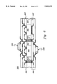
- FIG. 7a-7e are cross-sectional elevational views of one processing embodiment in accordance with the present invention for repairing the multichip module of FIG. 4;
- FIG. 8 is a cross-sectional elevational view of one embodiment of an enhanced multichip module, in accordance with the present invention, employing a release layer above the in situ processed dielectric layer;
- FIGS. 9a-9e are cross-sectional elevational views of one processing embodiment in accordance with the present invention for simultaneously repairing multiple multichip modules.
- FIG. 10 is a cross-sectional elevational view of one embodiment of a single chip module in accordance with the present invention.
- FIG. 4 depicts a basic multichip module, generally denoted 100, pursuant to the present invention.
- Structure 100 includes multiple bare chips 102 each of which has at least one side surface surrounded by a structural material 104.
- at least one chip of multiple chips 102 comprises an integrated circuit chip.
- other chips might comprise a capacitor chip or resistor chip.
- An in situ processed layer 106 is disposed physically on the upper surfaces of chips 102 and structural material 104. Via openings 108 are formed in the in situ processed layer 106 to expose at least some of the contact pads 107 at the upper surfaces of the integrated circuit chips.
- An intrachip metal layer 110 is provided on layer 106 such that metallization within each via opening 108 electrically connects to a corresponding contact pad 107.
- a structural material 104 which can be different from a first dielectric layer 106 on the upper surfaces of the chips; employing in situ processing to form dielectric layer 106, with layer 106 being preferably photo-patternable; a dielectric layer 106 comprising a homogenous layer physically disposed on the upper surfaces of the chips; the back surface of the module can have no substrate, such that a heat sink could be applied directly to the chips if desired; and finally, the chips may be of different thickness, or more preferably, of uniform thickness upon completion of fabrication of the multichip module.
- multichip module 100 can be fabricated by: adhesively bonding multiple bare chips to an alignment carrier; dispensing and curing the structural material about the chips; lapping the structure to a desired thickness, which may or may not expose the lower surfaces of the bare chips; transferring the structure to a process carrier by affixing the exposed back surface to the process carrier; and removing the alignment carrier.
- a photo-patternable dielectric can then be coated over the chips and the structural material, vias can be formed in the dielectric and metal (for example) deposited and patterned therein.
- Subsequent chip interconnect layers can then be conventionally added by alternately applying dielectric and metallization layers. Again, no special processing of the chips is required and photo-patterning of all dielectric layers is possible, including the first level dielectric.
- FIGS. 5a-5h depict one basic processing approach in accordance with the present invention.
- FIG. 5a depicts an alignment carrier 120 coated with an adhesive material 122.
- a sheet of flat glass has both the flatness and dimensional stability required. The glass is first cleaned to remove any particulate material. A suitable cleaning process is a 5 minute soak in Caros Acid (50/50 Sulfuric Acid and Hydrogen peroxide) followed by rinsing.
- a suitable adhesive material is hot melt adhesive HM-1 available from ZEON Technologies of Loundonberry, N.H. This material is spun coated to obtain a thickness of approximately 10 microns followed by drying at a temperature of 100° C. for 15 minutes. The alignment carrier is heated until the adhesive is tacky.
- an alignment carrier 120 has an adhesive structure 124 applied to an upper surface thereof.
- Structure 124 includes a release layer 126 physically contacting the upper surface of alignment carrier 120.
- This release layer may comprise a hot melt adhesive such as the adhesive ZTX HM-1 available from ZEON Technologies.
- a back grinding film tape 130 for example, type BT-150E-C6 available from Nitto Denko Corporation of Osaki, Japan, is laminated to the exposed surface of the double sided tape 128 so that an upper surface of the back grinding tape 130 presents an adhesive surface.
- Structure 124 allows the chips to be placed onto the alignment carrier at room temperature. Alternatively, the back grinding tape could be applied directly to the release layer under temperature sufficient to melt the release layer. Finally, the chips (not shown) could be removed from structure 124 by heating the release layer to remove the carrier, and then peeling back the grinding tape 130 with the double sided tape affixed thereto.
- chips 102 are placed accurately face down in adhesive 122 using a high accuracy pick and place machine such as available from MRS1 Micro Robotic Systems, Inc. of Chelmsform, Mass. This process accurately positions the chips in X and Y dimensions, as well as holding the chip faces parallel in the same plane.
- structural material 104 would be dispensed to fill the spaces between chips 102.
- a suitable filler material is UVE 1006 available from ZEON Technologies. This material can be cured by UV light using a UV curing system such as available from UV III of Bellingham Mass. Since the chips are not all the same thickness the resultant structure is back lapped, which is a well known process in the semi-conductor industry.
- Lapping preferably continues until a lower surface of each chip is exposed at a planar back surface 105 of the structure. Alternately, however, lapping could continue until only some, only one, or none of the lower surfaces of the chips are exposed.
- the thickness is not at all critical to the process. A thickness of 10 mil gives sufficient strength while meeting all but the most severe space constraint requirements. Note that for very space constrained conditions or where flexibility is desired, back lapping can continue to the limits of accuracy of the lapping system employed, which is usually below 1 mil.
- FIG. 5b depicts the alignment plate with chips and structural material lapped to a desired thickness such that a lower surface of each chip is exposed. By exposing the lower surfaces of the chips, it is possible to subsequently directly thermally couple a heat sink thereto.
- the assembly is next transferred to a process carrier 140.
- the process carrier is preprocessed with an adhesive and a release layer, together denoted 142.
- the adhesive holds the assembly through upper surface processing and the release layer facilitates release when processing is complete.
- Transfer to the process carrier is achieved by placing the alignment plate over the process carrier with the back surface of the chips and structural material in contact with the process carrier adhesive.
- the process carrier is coated with a Cyanoacrylate adhesive, while the lower surfaces of the chips and structural material are coated with the catalyst for the adhesive.
- curing of the adhesive is essentially instantaneous with physical contacting of the two surfaces.
- FIG. 5d shows the structure adhered to the process carrier 140 with the alignment plate removed and the front surface 103 of the chips and structural material cleaned and free of residual adhesive material.
- a photo-patternable dielectric 106 is spray or spin coated over front surface 103.
- a suitable photo-patternable material is Shipley Photo Dielectric available from Shipley Company, Inc. of Marlborough, Mass. This material is spun coated, for example to a thickness of 24 microns, exposed, developed and post-baked in accordance with the directions supplied by Shipley Company, Inc.
- metallization 110 is applied.. In one embodiment, metal is applied by sputtering. Commercial sputtering equipment such as a Balzers 801, manufactured by Blazers, Inc.
- Metal patterning is achieved by applying electrodeposited photoresist, such as Shipley Eagle 2100ED to a thickness of 6 microns, exposing and developing a pattern to allow pattern plating. Application, exposure and development conditions are as outlined in the Shipley Company spec. sheets. Copper is pattern plated using an acid copper plating bath at a current density of 20ASF. The resist is then stripped using Shipley product 2009 and the seed copper is stripped in Ammonium persulfate followed by Transene TFT etch of the titanium. At this point the basic structure shown in FIG.
- processing continues by coating additional layers of dielectric 144 and patterning additional layers of metallization 146 until the desired interchip interconnect 150 is achieved.
- I/O input/output
- FIG. 5g A gold plated pad grid 152 is achieved by pattern plating the copper to a thickness of approximately 1 mil or more, followed by plating nickel to 100 micro inches and then gold to 50 micro inches.
- Solder bumps 154 can be achieved by plating the copper to a thickness of 12 microns followed by solder plating of 8 microns. Solder balls or solder paste cones are placed at each site and reflowed to form the desired solder bump 154.
- FIG. 5g shows the two layer chip interconnect 150 and intrachip connect structure 106 in one basic embodiment.
- connect structure 106 could comprise an interchip metal level connect.
- a heat sink (not shown) can be attached directly to the back surface 105 of the package, thus providing direct thermal contact to the lower surfaces of the chips.
- FIG. 5h shows the basic structure singulated to form multiple single chip packages 160. Note that solder bumps or connection pads can be placed directly above or offset to the side of the bare chip, thus allowing any desired I/O pad array configuration to be produced for the single packaged chip.
- a means is provided for making electrical interconnection from an exposed top side of structure 200 to an exposed back side of the structure.
- this means is provided by placing conductive components 202, which may be conductive die or slugs, commensurate with placement of chips 102.
- conductive components 202 which may be conductive die or slugs, commensurate with placement of chips 102.
- front surface 103' to back surface 105' through connections are embedded in the structural material 104 between the chips.
- a circuit board 210 with additional interconnection layers is formed on or preprocessed and secured to back surface 105'.
- Conductive epoxy or solder can be used to make electrical connection from the preprocessed circuit board both to the embedded through connections 202 and to the lower surfaces of chips 102 as required.
- surface mount electronic components 220 can be added on both sides of structure 200 for mixed signals applications. This maximizes the number of components 220 which can be close to any active IC chips, and minimizes the overall volume required for a given interconnect structure.
- FIG. 5e shows a processing stage where chips 102 are attached to a carrier 140 and the first layer of dielectric 106 and the intrachip metal 110 have been applied and patterned.
- the chips can be conveniently tested either individually or as a functional group.
- a coating of gold can be applied by electroless deposition.
- a suitable electroless gold is EL221 supplied by Shipley Company, Inc.
- the gold which can be coated to a thickness of 10-20 micro inches, serves to improve contact to the test equipment.
- Contact is made through a Z-axis conductive elastomer to a pad array pattern (not shown) which matches the pad pattern on the module 100' surface.
- the Z-axis elastomer such as ECPI, is commercially available from AT&T.
- chips 102 are positioned as they will be positioned in the final module. This means that testing can occur by completing the circuit interconnect in a test board in the same way that it will be completed in the final module. Each individual module group can be tested by stepping the test board to each functional group and performing the necessary tests.
- FIGS. 7a-7e show one basic process flow embodiment for chip replacement.
- the first step is to transfer the module from the process carrier 140 (FIG. 5e) to an alignment plate 300 (FIG. 7a). This is done by placing the unfinished module 100' face down on the alignment plate 300 and heating the assembly in a laminating press with light pressure until an alignment plate adhesive 300 melts and forms an adhesive layer 302. The processing carrier is then removed and any residual processing carrier adhesive cleaned from the back surface 105 of the modules.
- the next step is to remove the defective chip(s) 102'. This can be done by mechanically milling around the chips or by using a laser to score the structural material and first level dielectric around the chip(s).
- the defective chip 102' can then be removed with a conventional heated rework tool which heats the chip 102' to the melt point of the adhesive 106 and withdraws chip 102'.
- the resultant structure with chip 102' removed is shown in FIG. 7b.
- the defective IC chip is replaced with an identical type chip 102" which has been preprocessed, pretested and packaged.
- the preprocessed chip can be fabricated using the same process steps as the modules shown in FIG. 5e. Multiple chips of the same type can be generally processed together to create a large supply of extra chips. These chips are then tested and singulated to provide the preprocessed and pretested chips 102". As shown in FIG. 7c, preprocessed chip 102" is accurately placed face down in the adhesive 302 and structural material 104 is added using the same processing steps outlined above.
- FIG. 7d shows the module at the same point as FIG. 5b.
- processing follows the process outlined above and depicted in FIG. 5b through FIG. 5e. Note that these processing steps can be carried out on chips which have been completely tested even as a group so that final processing yield does not suffer from the fall out of chips from wafer probe to incorporation in a module.
- the repaired module 100" is depicted in FIG. 7e. Note that the small amount of structural material 104 filling first dielectric layer 106 surrounding new chip 102" is acceptable.
- FIG. 7e module 100" has been affixed to a process carrier 304 for the formation of interchip metallization layers above the intrachip metallization 110.
- the repair of a finished module is discussed below in connection with FIGS. 9a-9e.
- one additional processing step can be incorporated in the basic fabrication method. This step, which is depicted in FIG. 8, would be substituted for or incorporated into the step of FIG. 5f in the basic fabrication method.
- the objective is to add a "transition" layer 322 in the second dielectric layer physically contacting the first dielectric layer 320. This will subsequently be used to aid in removal of interconnect layers (not shown) above the second dielectric 320. Lapping or grinding techniques can also be used to remove the overlying interconnect.
- the transition layer is added by spin coating a very thin layer of a thermoplastic such as polysulfone available from Union Carbide.
- the layer is baked to remove solvent and a second layer of photo-imageable dielectric 324 is spun, baked, exposed, and developed as described above for the first dielectric 106. After a suitable post bake, there will still be polysulfone in the via holes. This can be removed by plasma etching, during which the relatively thick photodielectric acts as a mask. Suitable etching conditions are 4 minutes at 400 watts with a 30 percent Carbontetrafluoride oxygen gas mixture. Metal is then applied and patterned, and subsequent layers are applied as outlined above.
- the overlying layers of interconnect are first stripped off, resulting in a structure such as shown in FIG. 9a. If the thermoplastic transition layer 322 was used then the overlying layers can be stripped off by heating the structure to the melting point of the thermoplastic and separating the multiple chip interconnect layers from the module. If grinding/lapping is to be used, then the module is ground to remove the overlying layers. The residue can be cleaned by etching any metal, followed by solvent or plasma cleaning of residue of the second dielectric. The cleaned module 100 is shown in FIG. 9b. This module 100 along with others like it is placed face down in an adhesive 402 (FIG. 9c) on an alignment carrier 400 using a precision pick and place mechanism in the same way as chips are placed in the basic fabrication method.
- an adhesive 402 FIG. 9c
- modules of the same type processed on different carriers may have different thicknesses. This does not pose a problem.
- Structural filler material 106 is dispensed and cured and the resultant structure is lapped to the desired thickness. It is necessary to lap to the thickness of the thinnest module to get good uniformity.
- the module is transferred from the alignment carrier 400 to a processing carrier 410 (FIG. 9e) as described above. All subsequent processing is identical to processing of an original module, including test and replacement of defective IC chips.
- the process carrier is a quartz plate.
- the module is bonded to the quartz plate using the cyano acrylate described above or using an UV curable epoxy such as UVE 1004 available from ZEON Technologies.
- the process carrier can be removed using an excimer laser.
- the excimer laser energy is aimed at the process carrier adhesive through the quartz plate which is transparent to UV.
- the process carrier adhesive absorbs the energy and vaporizes, which separates the carrier at the carrier-adhesive boundary. Suitable conditions are 200-500 mJ per cm squared per pulse width. Ten pulses might be required for each area to be removed. Scanning a narrow beam gives the best removal results.
- a release layer with a narrow melting point such as lead-tin solder can be used.
- the module is bonded to the release layer.
- the process carrier is held on a temperature controlled vacuum chuck. The temperature of the process carrier quickly reaches the melt point of the process carrier adhesive and the module is released before the melt point of the alignment carrier adhesive is reached.
- This process takes advantage of the relatively good thermal conductivity of the process carrier and the relatively poor thermal conductivity of the adhesive and dielectric layers which separate the process carrier and alignment carrier.
- FIG. 10 depicts by way of example a cross-sectional view of one embodiment of a single chip module, denoted 500, in accordance with the present invention.
- Module 500 includes an integrated circuit chip 502 having multiple contact pads 504 at an upper surface thereof.
- Chip 502 includes at least one side surface which extends between the upper surface of the bare chip and the lower surface of the chip. The at least one side surface is covered by a structural material 506 which may be the same as that employed above in connection with the multichip modules described herein.
- An appropriate metallization layer resides within the vias and includes solder bump contacts 510 for electrically connecting the single chip module 500 to an external structure, such as a printed circuit board.
- an external structure such as a printed circuit board.
- structural material 506 can be different from the in situ processed dielectric 508 above the integrated circuit chip.
- the width of the structural material may be increased as necessary to support a desirable pad configuration above the upper surface of the integrated circuit chip.
- the first dielectric layer preferably comprises a photo-patternable dielectric material.
- an electronic packaging and interconnect structure is disclosed herein within the broad category of chips first modules.
- the disclosed fabrication method is more cost effective than other chips first approaches, and can be used to fabricate both multichip as well as single chip packages. Further, the resultant structure is amenable to testing and subsequent replacement of a defective chip early in the fabrication process. Finished module repair methods are also disclosed.
- Several extensions of the basic structure are presented including a module with components on both side surfaces of the structure for space constrained/high performance applications.
- the fabrication method of the structure allows extremely thin modules to be fabricated, even to the point of flexibility of the resultant structure. Further, no special processing of the chips is required, and photo-patterning of all dielectric layers above the chips is possible. Also, a pad pitch which matches that of a circuit board to which the module is to be connected is possible, even for a single chip module, while still providing a thin module.
Landscapes
- Semiconductor Integrated Circuits (AREA)
- Production Of Multi-Layered Print Wiring Board (AREA)
Abstract
Multichip and single chip modules are presented as well as a chips first fabrication of such modules. The multichip module comprises a plurality of chips affixed in a planar array by a structural material which surrounds the sides of the chips such that the upper surfaces of the chips and an upper surface of the structural material are co-planar and the lower surface of at least one chip and a lower surface of the structural material are co-planar. A photo-patternable dielectric is disposed directly on the upper surfaces of the chips. The photo-patternable dielectric includes vias to at least some contact pads at the upper surfaces of the chips and the module further comprises an intrachip metallization layer on the photo-patternable dielectric layer. Subsequent processing provides a multi-layer chip interconnect structure over the intrachip metallization layer and photo-patternable dielectric. Testing and repair of the module can be accomplished prior to or subsequent to fabrication of the multi-layer chip interconnect. Formation of multiple single chip modules is accomplished by singulating the multichip module into individual packages.
Description
The present invention is generally related to multichip and single chip modules, and in particular, to the broad category of chips first fabrication of extremely thin multichip and single chip modules, as well as to repairable multichip modules.
The conventional approach to electronic packaging and interconnect has been to package individual integrated circuit (IC) chips in a single package and to attach these packages to a printed circuit board to provide interconnect between the individual IC chips. In recent years, this approach has met with problems of speed, size, and interconnect density due to ever constant demands for reduced size and increased performance from such integrated circuit packages.
Process speed is limited by the fact that individual packages have loading capacitance and inductance associated with their relatively long pins and by the large size of conductor runs in the packages relative to the size of the conductors of a bare IC chip. As the speed of computers and other devices continues to increase, the problem of providing electronic packaging and interconnect which provides maximum performance has become a significant challenge.
Size constraints are particularly prevalent in applications such as portable computers and other handheld electronic devices such as pagers and cellular phones. In these applications, more functionality is continually desired, but the form factor is limited. Thus, the general trend is towards overall decreased weight and size with ever increasing functionality. The problem is to produce electronic packaging and interconnect, which provides such high functionality, but requires minimum space.
Interconnect density is also increasing. As computer manufacturers attempt to increase performance, there is a trend towards wider data and address busses. This allows more data to be communicated in a given clock cycle. As a result, the number of pins on a computer chip is steadily growing. Conventional single chip packaging is being stretched to accommodate the growth in pin count and printed circuit boards are resorting to more layers and finer trace widths to provide interconnect between packages. The problem is that this is raising the cost and complexity of the individual packages, the printed circuit boards which provide the interconnect, and the methods of interconnection from the packages to the printed circuit boards.
One solution to many of the above problems is the MultiChip Module (MCM). In an MCM, bare (unpackaged) IC chips are interconnected by means of a miniature printed circuit board whose interconnect pitch may match the pitch on the IC chip themselves. There are presently two main classes of MCM. These are the chips last MCM and the chips first MCM. In the chips last MCM, the miniature circuit board is fabricated first and then the bare IC chips are attached and interconnected to the circuit board. The method of interconnect is usually wire bond or solder bump. In the chips first MCM, the chips are placed first relative to each other and a miniature circuit board is then built above the chips. The interconnect is formed to the IC chips as an integral part of the processing of the circuit board.
Structures in accordance with the present invention fall into the category of chips first MCMs. In the interest of brevity, only the relevant chips first art is discussed below and, where generic problems of MCMs are pertinent, they are also discussed.
One of the major problems facing the MCM industry is the problem of assuring that the chips which are used in an MCM are 100 percent good. Presently, chips are tested at the bare chip level only to the extent necessary to assure that the chips will probably be good if packaged. Typical yields experienced in the industry are 80 to 97 percent from receipt of the bare chip to complete test and burn-in of the packaged part. Since the yields are multiplicative, the yield of a finished 10 chip MCM using such bare chips will run from 10 to 74 percent. This is obviously not a sufficient yield for a viable MCM business. Thus, some chip vendors are beginning to supply bare chips in fully tested and even burned-in form. These so called "Known Good Die" are supplied at a cost which runs from 3× the packaged part cost to as low as 1× the packaged part cost. Even at 1× packaged part cost, however, this doesn't present a viable business scenario because much of the contributed value of the MCM vendor is the packaging of the bare IC chip. A desirable objective is thus to provide a method and structure whereby chips can be tested and burned-in economically before being committed to the MCM. The subject invention addresses this object.
A further problem in chip testing exists in that multiple chips must work together for the system to function properly. In order to accommodate this fact individual chips are "guard-banded" so that the worst case of all chips in a system can be combined and still work together. This leads to discarding a percentage of chips which typically would have worked in the system, but under worst case combinations would fail. The subject invention solves this problem as well. An additional issue is to test chips as combined chip sets before final incorporation into an MCM. The subject invention also addresses this issue. Even with very complex testing systems, the interaction of complex chips may not be completely simulated by the tester, thereby resulting in undesirable surprises when chips are combined in a system.
Repair of finished MCMs is another major issue which faces the MCM industry. In the chips last approach, the methods of repair differ based upon the original method of interconnect of the chip to the circuit board. In the case of wire bonding, all the wire bonds are broken and the bad chip is removed. A new chip is then placed at the old site and new wire bonds are formed at previously unused sites. This leads to the requirement that additional bonding sites be provided for all chips, whether these sites are ultimately used or not. In addition, there is a significant risk of damage to the circuit board during chip and wire bond removal operations which would necessitate scrapping the entire module. Risk of damage is also a problem with solder bump approaches. With solder bumps, careful burnishing preparation of the solder bump sites must be accomplished to assure that the next chip will make proper connection to the circuit board. In the chips last approach, if the interconnecting circuit board is defective there is no repair procedure possible once the board is populated with chips, necessitating scrapping of the module.
In many low cost approaches no method of repair is provided. This constrains these approaches to those systems where the cost of chips is sufficiently low or the value of the form factor sufficiently high that the penalty of scrapping modules can be withstood. Two significant prior art approaches take this route. The first is the so called "chip on board" approach wherein: the circuit board is formed by conventional laminated printed circuit methods; chips are placed on the board; and then wire bonded to the board and covered with an encapsulant for protection. The second is the so called "Plastic Encapsulated MCM". This approach is a chips first approach wherein chips are encapsulated on one side by plastic encapsulant and the circuit board is built above the chips on the other side. With the plastic encapsulant surrounding the chips there is no way to remove them for repair. This fact is discussed in an article by Fillion and Daum entitled: "CAD/CIM Requirements In Support of Plastic Encapsulated MCM Technology For High Volume Low Cost Electronics," Advancing Microelectronics (September/October 1994). The subject invention is also a chips first technique, but is distinguishable in several ways from the conventional art, one of which is the ability to repair the resultant module.
Two major approaches to chips first are the Advanced Multi-Chip Module (AMCM) approach, and the High Density Interconnect (HDI) approach, along with its offshoots including the Plastic Encapsulated MCM.
A representative cross-section of an AMCM structure, generally denoted 10, is shown in FIG. 1. In the AMCM approach, chips 12 are ground to a precise thickness and accurately placed on a flat substrate 14. Encapsulant 16 is dispensed over the chips 12 and in the area between chips, after which the encapsulant is planarized above the chips. The combination of a controlled chip thickness and accurate planarization of encapsulant above the chips leads to a relatively controlled layer of polymer above the tops of the chips. Via holes are formed in the encapsulant above the pads of the IC chips using an excimer laser. Chip interconnect metallization 18 is sputtered on the surface of encapsulant 16 and in the via holes. The metallization is subsequently built up electrolytically and patterned by photolithographic means. Additional interconnection layers 20 are then built up as required by depositing dielectric, forming via holes, metallizing and patterning.
Several problems exist with structure 10 of FIG. 1. First, the thickness of the chips and of the substrate must be accurately controlled in order to control the thickness of the dielectric above the chips. This is a relatively time consuming and expensive process. Second, the encapsulant surrounds the chips both on the sides and above the chips. The desirable characteristics of the encapsulant above the chips, i.e., as a dielectric, and on the sides of the chips, where used primarily as mechanical support, are conflicting. This necessitates a compromise in properties where the dielectric properties are not optimum from an electrical view and the mechanical properties are not optimum from a structural view. The subject invention addresses this disadvantage of the AMCM approach by providing a structure wherein the mechanical support portion between chips and dielectric portion above the chips can be wholly different materials.
A representative cross-section of an HDI structure, denoted 30, is shown in FIG. 2. In the HDI approach, instead of thinning chips to a predetermined thickness the substrate 32 is machined with wells 34 of different depths. When the chips 36 are placed in the substrate wells, the tops of the chips are disposed even with the top surface of the substrate. An adhesive is applied to the tops of the chips and a pre-processed layer of polymer film 38 is laminated above the chips 36. Via holes are formed in this overlay layer 38 above the pads 39 of the IC chips 36. Metallization 40 is sputtered on the surface of the overlay layer 38 and in the via holes. The metallization is subsequently built up electrolytically and patterned by photolithographic means. Additional interconnection layers 42 are built up as required by depositing dielectric using coating or laminating means, forming via holes, then metallizing and patterning.
One advantage of structure 30 over the AMCM structure 10 of FIG. 1 is that the thickness of the first layer is only dependent on the thickness of the adhesive and the preformed polymer layer 38. It does not require maintaining tight tolerances on the thickness of the chips or flatness of the substrate. Several problems, however, exist with structure 30. First, machining the substrate to fine tolerances is time consuming and expensive. Second, the overlay layer is unsupported in the well space between chips. Where unsupported, the overlay layer sags and makes lithography difficult. Also, because the chips are in wells, there is no support for pads of an input/output (I/O) layer in the area between chips sharing a common well. These drawbacks can be accommodated somewhat by the use of individual wells for chips, but this is at the expense of increasing package size. The subject invention is a chips first approach that avoids the above-outlined disadvantages of the HDI approach.
In an effort to make a lower cost system, a "Plastic Encapsulated MCM" structure 50, such as depicted in FIG. 3, has been proposed. In this approach, which comprises a variation on the basic HDI approach, the machined substrate is replaced by a plastic encapsulation 52. The basic structure 50 is fabricated by a different set of steps than the HDI approach. Specifically, during fabrication the chips 54 are placed down onto an adhesively coated polymer film that is held to a flat platen. The plastic encapsulation 52 is then formed about the chips. As shown, this plastic encapsulation forms the substrate that protects and supports the chips. Thereafter the structure is removed from the platen and the conventional HDI interconnect structure 56 is formed. Again, a first layer applied above the chips comprises a pre-processed film 58 which is adhesively cured to the IC chips. Unfortunately, there are several identifiable problems with the resultant structure.
First, the structure cannot be repaired, which can be a significant consideration in many applications. In addition, the structure is not inherently thermally efficient because plastic encapsulant is a poor thermal conductor. To combat this, the incorporation of thermal "slugs" beneath chips has been proposed. This, however, adds to process cost and complexity. Further, in applications where space is at a premium the plastic encapsulant adds an undesired thickness to the structure. The subject invention overcomes these drawbacks with a simple structure which maintains the advantages of both the HDI and the AMCM approaches.
Another object achieved by the methods of the subject invention relates to the formation of all layers using photo-imageable polymers. It is desirable to use photo-imageable polymers for the dielectric layers because via holes can be formed therein by simple lithography rather than the more complex methods of laser ablation or plasma etching. In the HDI approach, a preformed film is adhesively bonded over the tops of the chips. In the Plastic Encapsulated MCM technique, the chips are first placed face down on an adhesive coated, preformed film which is attached to a platen. The encapsulant is dispensed and cured, and the structure is removed from the platen for subsequent processing. In both cases the result is the same: there is a preformed film adhesively bonded to the IC chips. The only method of forming vias in a preformed film employs etching means such as laser ablation or plasma etching, either of which may cost three times the process cost associated with photo-patterning. Note that present technology does not provide for a preformed film which could be adhesively bonded to IC chips and which is photo-patternable. Essentially, photo-patternable films must be formed in situ above the integrated circuit chips.
In the AMCM approach, a structural dielectric is employed between and above the integrated circuit chips as shown in FIG. 1. The requirement of a structural dielectric to surround the chips negates the use of a photo-patternable dielectric since photo-imageable dielectrics are solvent born. More particularly, once the photo-patternable material is in place between the chips, it would be difficult to remove the solvent and, even if possible, a high degree of shrinkage would accompany the process such that the resultant structure would in all likelihood be non-planar. Further, it would be difficult to employ a photo-patternable dielectric in the thickness required to implement an AMCM. Finally, with an AMCM structure, it is desirable to cure the encapsulant fully and planarize before forming the interconnect wiring above the encapsulant but if a photo-dielectric is fully cured, then the material is no longer photo-patternable.
The following example is provided for appreciating the higher cost and process complexity required to form via openings in the encapsulant of the AMCM approach. This process comprises sputtering a mask of copper above the encapsulant, applying photoresist to the mask, exposing and developing the photoresist, etching the mask using the photoresist pattern, stripping the photoresist, building the mask electrolytically by electroplating, laser scanning to ablate polymer exposed by the mask, and then removing the mask. Actual costs associated with this approach may be three times or more the costs associated with using a photo-patternable material. Further, processing time required to complete the above-outlined via formation may be on the order of seven hours, while a photo-dielectric material can be applied, exposed and developed in approximately one hour of processing time.
For all of the above reasons, present technology does not allow for the use of a photo-patternable dielectric as the first level dielectric with either the AMCM approach or the HDI approach, including the offshoots thereof.
The preformed film of the HDI approach presents another disadvantage in structures where a portion of the chip is very sensitive to being coated with a dielectric, such as coils on high frequency RF devices. The only way to remove the dielectric from the sensitive area is by aggressive means, such as laser ablation or other etching means which tend to damage the sensitive chip area. Photo-imageable materials, on the other hand, can be removed with a non-aggressive development step, thus leaving sensitive areas intact.
While the subject invention is applicable to multichip modules, it is also applicable to fabrication of low cost, high performance single chip packaging. The basic problem in single chip packaging is to provide connection from the pads of the chip to the pads of the circuit board in the most cost effective and reliable manner while still providing the electrical and thermal performance necessary. With existing single chip structures, chip pads are connected by solder balls to small circuit boards which contain solder bumps on the opposite side. This process has two drawbacks; first it requires the use of chips which have solder balls and second it often requires the use of an underfill polymer to take up the expansion difference between the circuit board and the chip. Without the underfill, the solder balls are stressed beyond their elastic limit and fail prematurely during thermal cycling. In a second "chip scale" packaging approach, a wafer is covered with a relatively thick "buffer" layer of polymer, vias are formed and patterned metal makes contact to the chip pads. Solder bumps are then formed on top of the chips. In this structure the solder bump array is necessarily restricted to the size of the chip. If, for example, the chip undergoes a design rule shrink, the package must change accordingly. The subject invention avoids this drawback of the prior art.
In view of the above discussion, a main object of the invention is to provide an electronic packaging and interconnect means which can be used to provide cost effective packing and interconnect for single IC chips, and for multiple IC chips and related components.
Another object of the invention is to provide an electronic packaging and interconnect means wherein the IC chips can be tested and burned-in in final configuration, and where defective IC chips can be identified and replaced before substantial processing investment accrues.
Another object of the invention is to provide an electronic packaging and interconnect means where both defective chips and defective interconnect can be replaced in finished modules, and where reprocessing can occur on a carrier which carries multiple modules through the process.
A further object of the invention is to provide a chips first electronic packaging and interconnect means where tight control of the thickness of the chips and/or flatness of the substrate is unnecessary, while still retaining tight control of the thickness of the first dielectric layer.
Another object of the invention is to provide a chips first electronic packaging and interconnect means where the dielectric directly above the chips comprises an in situ processed material which is preferably a photo-patternable dielectric.
Yet another object of the invention is to provide a chips first electronic packaging and interconnect means where the dielectric above the chips can comprise a material different from the structural material which surrounds and physically interconnects the chips.
Still another object of the invention is to provide an electronic packaging and interconnect structure having minimum thickness to address space constrained applications.
A still further object of the invention is to provide an electronic packaging and interconnect structure which has no substrate and which can be attached to a low cost heat sink or other unfinished substrate.
Still another object of the invention is to provide an electronic packaging and interconnect structure wherein a planar main surface of each integrated circuit chip is exposed at a main surface of the resultant packaging.
Yet another object of the invention is to provide an electronic packaging and interconnect structure which can accommodate back surface interconnect configurations and interconnection vias from the front surface to the back surface of the package.
Another object of the invention is to provide an electronic packaging and interconnect structure where direct connection to the chips can be achieved without preprocessing of the chips, including application of solder bumps, thinning of the chips, or addition of special polymers and metallization layers.
Still another object of the invention is to provide an electronic packaging and interconnect structure which is inherently capable of high power dissipation.
Briefly summarized, the invention comprises in a first aspect a multichip module that includes a plurality of chips, each comprising an unpackaged chip having at least one side surface, an upper surface, a lower surface, and at least one contact pad at the upper surface. A structural material surrounds the at least one side surface of each chip and mechanically interconnects in spaced planar relationship the plurality of chips. The structural material has an upper surface co-planar with the upper surfaces of the plurality of chips thereby forming a front surface, and a lower surface substantially parallel with the lower surfaces of the plurality of chips, thereby forming a back surface. An in situ processed layer is disposed on the front surface. The in situ processed layer comprises a dielectric material that is different from the structural material which mechanically interconnects the plurality of chips.
This in situ processed layer includes via openings to at least some contact pads at the upper surfaces of the plurality of chips for electrical connection to those contact pads. Preferably, the in situ processed layer comprises a photo-patternable dielectric, and a metallization layer is disposed directly on the photo-patternable dielectric. The metallization layer includes metallization within each via opening electrically connecting to the corresponding exposed contact pad. As an extrapolation, an integrated circuit chip module is also depicted and claimed herein. This single chip module is similar to the multichip module summarized herein except the packaging is directed to a single chip.
A method for fabricating a multichip module is also presented. The method includes the steps of: providing a plurality of chips, each chip comprising a bare chip having at least one side, an upper surface, a lower surface, and a contact pad at the upper surface; placing the plurality of chips on an alignment carrier in spaced relation with the upper surfaces thereof facing the alignment carrier; surrounding the plurality of chips with a structural material such that the at least one side surface of each chip is covered by the structural material and an exposed surface of the structural material is substantially parallel with the lower surfaces of the plurality of chips, thereby defining a back surface; affixing the back surface to a process carrier, and separating the alignment carrier from the plurality of chips; forming by in situ processing a dielectric layer directly on the upper surfaces of the plurality of chips. Further processing can include patterning and forming vias in the in situ formed dielectric layer, the vias being disposed to expose at least some contact pads at the upper surfaces of the chips for facilitating electrical connection thereto; and forming metallization structures above said in situ processed dielectric so that metallization within said vias electrically connect to at least some contact pads exposed by said vias. Again, the in situ processed dielectric layer preferably comprises a photo-patternable dielectric, and metallization is disposed within the via openings formed within the photo-patternable dielectric.
To restate, an electronic packaging and interconnect structure is disclosed herein within the broad category of chips first modules. The disclosed fabrication method is more cost effective than other chips first approaches, and can be used to fabricate both multichip as well as single chip packages. Further, the resultant structure is amenable to testing and subsequent replacement of a defective chip early in the fabrication process. Finished module repair methods are also disclosed. Several extensions of the basic structure are presented including a module with components on both side surfaces of the structure for space constrained/high performance applications. The fabrication method of the structure allows extremely thin modules to be fabricated, even to the point of flexibility of the resultant structure. Further, no special processing of the chips is required, and photo-patterning of all dielectric layers above the chips is possible. Also, a pad pitch which matches that of a circuit board to which the module is to be connected is possible, even for a single chip module, while still providing a thin module.
The subject matter which is regarded as the present invention is particularly pointed out and distinctly claimed in the concluding portion of the specification. The invention, however, both as to organization and methods of practice, together with further objects and advantages thereof, may best be understood by reference to the following detailed description taken in conjunction with the accompanying drawings in which:
FIG. 1 is a cross-sectional elevational view of one embodiment of a conventional advanced multichip module (AMCM);
FIG. 2 is a cross-sectional elevational view of one embodiment of a conventional high density interconnect (HDI) multichip module;
FIG. 3 is a cross-sectional elevational view of one embodiment of a conventional plastic encapsulated HDI multichip module;
FIG. 4 is a cross-sectional elevational view of one embodiment of a multichip module in accordance with the present invention;
FIGS. 5a-5h are cross-sectional elevational views of process structures attained during manufacturing of a multichip module, such as the module of FIG. 4, in accordance with the present invention;
FIG. 6 is a cross-sectional elevational view of one embodiment of a mixed signal application module in accordance with the present invention having front surface and back surface interconnect and a surface mount component at both surfaces;
FIG. 7a-7e are cross-sectional elevational views of one processing embodiment in accordance with the present invention for repairing the multichip module of FIG. 4;
FIG. 8 is a cross-sectional elevational view of one embodiment of an enhanced multichip module, in accordance with the present invention, employing a release layer above the in situ processed dielectric layer;
FIGS. 9a-9e are cross-sectional elevational views of one processing embodiment in accordance with the present invention for simultaneously repairing multiple multichip modules; and
FIG. 10 is a cross-sectional elevational view of one embodiment of a single chip module in accordance with the present invention.
FIG. 4 depicts a basic multichip module, generally denoted 100, pursuant to the present invention. Structure 100 includes multiple bare chips 102 each of which has at least one side surface surrounded by a structural material 104. Preferably, at least one chip of multiple chips 102 comprises an integrated circuit chip. By way of example, other chips might comprise a capacitor chip or resistor chip. An in situ processed layer 106 is disposed physically on the upper surfaces of chips 102 and structural material 104. Via openings 108 are formed in the in situ processed layer 106 to expose at least some of the contact pads 107 at the upper surfaces of the integrated circuit chips. An intrachip metal layer 110 is provided on layer 106 such that metallization within each via opening 108 electrically connects to a corresponding contact pad 107.
Significant features of structure 100 to note include: a structural material 104 which can be different from a first dielectric layer 106 on the upper surfaces of the chips; employing in situ processing to form dielectric layer 106, with layer 106 being preferably photo-patternable; a dielectric layer 106 comprising a homogenous layer physically disposed on the upper surfaces of the chips; the back surface of the module can have no substrate, such that a heat sink could be applied directly to the chips if desired; and finally, the chips may be of different thickness, or more preferably, of uniform thickness upon completion of fabrication of the multichip module.
By way of process overview, multichip module 100 can be fabricated by: adhesively bonding multiple bare chips to an alignment carrier; dispensing and curing the structural material about the chips; lapping the structure to a desired thickness, which may or may not expose the lower surfaces of the bare chips; transferring the structure to a process carrier by affixing the exposed back surface to the process carrier; and removing the alignment carrier. At this point, the upper surfaces of the chips are exposed in the same plane as an upper surface of the structural material. A photo-patternable dielectric can then be coated over the chips and the structural material, vias can be formed in the dielectric and metal (for example) deposited and patterned therein. Subsequent chip interconnect layers can then be conventionally added by alternately applying dielectric and metallization layers. Again, no special processing of the chips is required and photo-patterning of all dielectric layers is possible, including the first level dielectric. FIGS. 5a-5h depict one basic processing approach in accordance with the present invention.
FIG. 5a depicts an alignment carrier 120 coated with an adhesive material 122. A sheet of flat glass has both the flatness and dimensional stability required. The glass is first cleaned to remove any particulate material. A suitable cleaning process is a 5 minute soak in Caros Acid (50/50 Sulfuric Acid and Hydrogen peroxide) followed by rinsing. A suitable adhesive material is hot melt adhesive HM-1 available from ZEON Technologies of Loundonberry, N.H. This material is spun coated to obtain a thickness of approximately 10 microns followed by drying at a temperature of 100° C. for 15 minutes. The alignment carrier is heated until the adhesive is tacky.
An alternate approach to the structure of FIG. 5a is depicted in FIG. 5a'. In this figure, an alignment carrier 120 has an adhesive structure 124 applied to an upper surface thereof. Structure 124 includes a release layer 126 physically contacting the upper surface of alignment carrier 120. This release layer may comprise a hot melt adhesive such as the adhesive ZTX HM-1 available from ZEON Technologies. A double sided tape 128, such as available from Tesa Tape, Inc. of Charlotte, N.C., is applied over release layer 126. Finally, a back grinding film tape 130, for example, type BT-150E-C6 available from Nitto Denko Corporation of Osaki, Japan, is laminated to the exposed surface of the double sided tape 128 so that an upper surface of the back grinding tape 130 presents an adhesive surface. Structure 124 allows the chips to be placed onto the alignment carrier at room temperature. Alternatively, the back grinding tape could be applied directly to the release layer under temperature sufficient to melt the release layer. Finally, the chips (not shown) could be removed from structure 124 by heating the release layer to remove the carrier, and then peeling back the grinding tape 130 with the double sided tape affixed thereto.
Returning to FIG. 5a, chips 102 are placed accurately face down in adhesive 122 using a high accuracy pick and place machine such as available from MRS1 Micro Robotic Systems, Inc. of Chelmsform, Mass. This process accurately positions the chips in X and Y dimensions, as well as holding the chip faces parallel in the same plane. Next, structural material 104 would be dispensed to fill the spaces between chips 102. A suitable filler material is UVE 1006 available from ZEON Technologies. This material can be cured by UV light using a UV curing system such as available from UV III of Bellingham Mass. Since the chips are not all the same thickness the resultant structure is back lapped, which is a well known process in the semi-conductor industry. Lapping preferably continues until a lower surface of each chip is exposed at a planar back surface 105 of the structure. Alternately, however, lapping could continue until only some, only one, or none of the lower surfaces of the chips are exposed. The thickness is not at all critical to the process. A thickness of 10 mil gives sufficient strength while meeting all but the most severe space constraint requirements. Note that for very space constrained conditions or where flexibility is desired, back lapping can continue to the limits of accuracy of the lapping system employed, which is usually below 1 mil. FIG. 5b depicts the alignment plate with chips and structural material lapped to a desired thickness such that a lower surface of each chip is exposed. By exposing the lower surfaces of the chips, it is possible to subsequently directly thermally couple a heat sink thereto.
Referring to FIG. 5c, the assembly is next transferred to a process carrier 140. The process carrier is preprocessed with an adhesive and a release layer, together denoted 142. The adhesive holds the assembly through upper surface processing and the release layer facilitates release when processing is complete. Transfer to the process carrier is achieved by placing the alignment plate over the process carrier with the back surface of the chips and structural material in contact with the process carrier adhesive. Preferably, the process carrier is coated with a Cyanoacrylate adhesive, while the lower surfaces of the chips and structural material are coated with the catalyst for the adhesive. Thus, curing of the adhesive is essentially instantaneous with physical contacting of the two surfaces. Once the process carrier adhesive cures, the alignment carrier can be removed by heating the structure to the melting point of the alignment carrier adhesive and lifting the plate away. Any residual adhesive is cleaned away by a suitable solvent. Acetone completely solvents residual ZTX HM-1. FIG. 5d shows the structure adhered to the process carrier 140 with the alignment plate removed and the front surface 103 of the chips and structural material cleaned and free of residual adhesive material. Those skilled in the art should note that a significant advantage of the present invention is inherent in the structure depicted in FIG. 5d, wherein an upper surface of material 104 is co-planar with the upper surfaces of chips 102. This inherent co-planarity facilitates subsequent processing steps above the upper surface of the chips.
In the next step, a photo-patternable dielectric 106 is spray or spin coated over front surface 103. A suitable photo-patternable material is Shipley Photo Dielectric available from Shipley Company, Inc. of Marlborough, Mass. This material is spun coated, for example to a thickness of 24 microns, exposed, developed and post-baked in accordance with the directions supplied by Shipley Company, Inc. Next, metallization 110 is applied.. In one embodiment, metal is applied by sputtering. Commercial sputtering equipment such as a Balzers 801, manufactured by Blazers, Inc. of Hudson, N.H., is used to sputter etch the oxide on the aluminum, coat an adhesion layer of titanium to 1000 angstroms and coat a seed copper layer to a thickness of 0.5 micron. Metal patterning is achieved by applying electrodeposited photoresist, such as Shipley Eagle 2100ED to a thickness of 6 microns, exposing and developing a pattern to allow pattern plating. Application, exposure and development conditions are as outlined in the Shipley Company spec. sheets. Copper is pattern plated using an acid copper plating bath at a current density of 20ASF. The resist is then stripped using Shipley product 2009 and the seed copper is stripped in Ammonium persulfate followed by Transene TFT etch of the titanium. At this point the basic structure shown in FIG. 5e has been achieved. Again, it is significant to note that the first layer of dielectric is patterned using a photo-patternable dielectric. This invention is the only known chips first process which allows this. An optional departure in the process flow can be made at this stage by testing the chips either individually or in groups, and thereafter replacing any defective chip. In this way, additional processing can continue with 100 percent good chips. Details of this option are described further below in connection with FIGS. 7a-9e.
As shown in FIG. 5f, processing continues by coating additional layers of dielectric 144 and patterning additional layers of metallization 146 until the desired interchip interconnect 150 is achieved. Several options for input/output (I/O) structures are enabled by this structure. Two options are shown in FIG. 5g. A gold plated pad grid 152 is achieved by pattern plating the copper to a thickness of approximately 1 mil or more, followed by plating nickel to 100 micro inches and then gold to 50 micro inches. Solder bumps 154 can be achieved by plating the copper to a thickness of 12 microns followed by solder plating of 8 microns. Solder balls or solder paste cones are placed at each site and reflowed to form the desired solder bump 154. Note that the solder bump 154 or pad 152 can be directly above the chip or offset from the chip 102. This increases the usefulness of this technology over other approaches to both single and multiple chip packaging and interconnect. FIG. 5g shows the two layer chip interconnect 150 and intrachip connect structure 106 in one basic embodiment. Alternatively, and as noted above, connect structure 106 could comprise an interchip metal level connect. After removal of the process carrier, a heat sink (not shown) can be attached directly to the back surface 105 of the package, thus providing direct thermal contact to the lower surfaces of the chips. FIG. 5h shows the basic structure singulated to form multiple single chip packages 160. Note that solder bumps or connection pads can be placed directly above or offset to the side of the bare chip, thus allowing any desired I/O pad array configuration to be produced for the single packaged chip.
In high space constrained applications or in applications where it is desirable to have as much chip interconnect as possible close to the active devices, an extension of the basic structure is possible. In this enhanced structure, denoted 200 in FIG. 6, a means is provided for making electrical interconnection from an exposed top side of structure 200 to an exposed back side of the structure. In one embodiment, this means is provided by placing conductive components 202, which may be conductive die or slugs, commensurate with placement of chips 102. Thus, when the assembly is removed from the process carrier, front surface 103' to back surface 105' through connections are embedded in the structural material 104 between the chips. To complete the structure, a circuit board 210 with additional interconnection layers is formed on or preprocessed and secured to back surface 105'. Conductive epoxy or solder can be used to make electrical connection from the preprocessed circuit board both to the embedded through connections 202 and to the lower surfaces of chips 102 as required. Finally, surface mount electronic components 220 can be added on both sides of structure 200 for mixed signals applications. This maximizes the number of components 220 which can be close to any active IC chips, and minimizes the overall volume required for a given interconnect structure.
FIG. 5e shows a processing stage where chips 102 are attached to a carrier 140 and the first layer of dielectric 106 and the intrachip metal 110 have been applied and patterned. At this stage, the chips can be conveniently tested either individually or as a functional group. To enhance contact to the chips, a coating of gold can be applied by electroless deposition. A suitable electroless gold is EL221 supplied by Shipley Company, Inc. The gold, which can be coated to a thickness of 10-20 micro inches, serves to improve contact to the test equipment. Contact is made through a Z-axis conductive elastomer to a pad array pattern (not shown) which matches the pad pattern on the module 100' surface. The Z-axis elastomer, such as ECPI, is commercially available from AT&T. Note that during testing, chips 102 are positioned as they will be positioned in the final module. This means that testing can occur by completing the circuit interconnect in a test board in the same way that it will be completed in the final module. Each individual module group can be tested by stepping the test board to each functional group and performing the necessary tests.
The following process outlines the steps to replace a defective chip identified during a testing process as outlined above. Note that the ability to test chips in final placement but before much interchip interconnect processing has occurred, can significantly improve the cost effectiveness and final yield of the process. FIGS. 7a-7e show one basic process flow embodiment for chip replacement. The first step is to transfer the module from the process carrier 140 (FIG. 5e) to an alignment plate 300 (FIG. 7a). This is done by placing the unfinished module 100' face down on the alignment plate 300 and heating the assembly in a laminating press with light pressure until an alignment plate adhesive 300 melts and forms an adhesive layer 302. The processing carrier is then removed and any residual processing carrier adhesive cleaned from the back surface 105 of the modules.
The next step is to remove the defective chip(s) 102'. This can be done by mechanically milling around the chips or by using a laser to score the structural material and first level dielectric around the chip(s). The defective chip 102' can then be removed with a conventional heated rework tool which heats the chip 102' to the melt point of the adhesive 106 and withdraws chip 102'. The resultant structure with chip 102' removed is shown in FIG. 7b.
Next, the defective IC chip is replaced with an identical type chip 102" which has been preprocessed, pretested and packaged. The preprocessed chip can be fabricated using the same process steps as the modules shown in FIG. 5e. Multiple chips of the same type can be generally processed together to create a large supply of extra chips. These chips are then tested and singulated to provide the preprocessed and pretested chips 102". As shown in FIG. 7c, preprocessed chip 102" is accurately placed face down in the adhesive 302 and structural material 104 is added using the same processing steps outlined above. Note that the new chip 102" might deliberately be made slightly thicker than the desired module thickness so that when the circuit is lapped to the desired thickness, essentially the only chip which is thinned is the new chip and the structural filler around this chip. FIG. 7d shows the module at the same point as FIG. 5b. Thus, from this stage processing follows the process outlined above and depicted in FIG. 5b through FIG. 5e. Note that these processing steps can be carried out on chips which have been completely tested even as a group so that final processing yield does not suffer from the fall out of chips from wafer probe to incorporation in a module. The repaired module 100" is depicted in FIG. 7e. Note that the small amount of structural material 104 filling first dielectric layer 106 surrounding new chip 102" is acceptable. This material need not comprise photo-patternable material since the via openings have already been made to the contact pads at the upper surfaces of the chips. In FIG. 7e module 100" has been affixed to a process carrier 304 for the formation of interchip metallization layers above the intrachip metallization 110.
The repair of a finished module is discussed below in connection with FIGS. 9a-9e. To make repair processing easier, one additional processing step can be incorporated in the basic fabrication method. This step, which is depicted in FIG. 8, would be substituted for or incorporated into the step of FIG. 5f in the basic fabrication method. The objective is to add a "transition" layer 322 in the second dielectric layer physically contacting the first dielectric layer 320. This will subsequently be used to aid in removal of interconnect layers (not shown) above the second dielectric 320. Lapping or grinding techniques can also be used to remove the overlying interconnect. The transition layer is added by spin coating a very thin layer of a thermoplastic such as polysulfone available from Union Carbide. The layer is baked to remove solvent and a second layer of photo-imageable dielectric 324 is spun, baked, exposed, and developed as described above for the first dielectric 106. After a suitable post bake, there will still be polysulfone in the via holes. This can be removed by plasma etching, during which the relatively thick photodielectric acts as a mask. Suitable etching conditions are 4 minutes at 400 watts with a 30 percent Carbontetrafluoride oxygen gas mixture. Metal is then applied and patterned, and subsequent layers are applied as outlined above.
To repair a finished module, the overlying layers of interconnect are first stripped off, resulting in a structure such as shown in FIG. 9a. If the thermoplastic transition layer 322 was used then the overlying layers can be stripped off by heating the structure to the melting point of the thermoplastic and separating the multiple chip interconnect layers from the module. If grinding/lapping is to be used, then the module is ground to remove the overlying layers. The residue can be cleaned by etching any metal, followed by solvent or plasma cleaning of residue of the second dielectric. The cleaned module 100 is shown in FIG. 9b. This module 100 along with others like it is placed face down in an adhesive 402 (FIG. 9c) on an alignment carrier 400 using a precision pick and place mechanism in the same way as chips are placed in the basic fabrication method. Note that it is possible that modules of the same type processed on different carriers may have different thicknesses. This does not pose a problem. Structural filler material 106 is dispensed and cured and the resultant structure is lapped to the desired thickness. It is necessary to lap to the thickness of the thinnest module to get good uniformity. At this point, the module is transferred from the alignment carrier 400 to a processing carrier 410 (FIG. 9e) as described above. All subsequent processing is identical to processing of an original module, including test and replacement of defective IC chips.
Two methods for transfer from the process carrier to the alignment carrier are disclosed. In the first method the process carrier is a quartz plate. The module is bonded to the quartz plate using the cyano acrylate described above or using an UV curable epoxy such as UVE 1004 available from ZEON Technologies. After the module is bonded to the alignment carrier the process carrier can be removed using an excimer laser. The excimer laser energy is aimed at the process carrier adhesive through the quartz plate which is transparent to UV. The process carrier adhesive absorbs the energy and vaporizes, which separates the carrier at the carrier-adhesive boundary. Suitable conditions are 200-500 mJ per cm squared per pulse width. Ten pulses might be required for each area to be removed. Scanning a narrow beam gives the best removal results.
In a second approach, a release layer with a narrow melting point such as lead-tin solder can be used. The module is bonded to the release layer. To release the module, the process carrier is held on a temperature controlled vacuum chuck. The temperature of the process carrier quickly reaches the melt point of the process carrier adhesive and the module is released before the melt point of the alignment carrier adhesive is reached. This process takes advantage of the relatively good thermal conductivity of the process carrier and the relatively poor thermal conductivity of the adhesive and dielectric layers which separate the process carrier and alignment carrier.
FIG. 10 depicts by way of example a cross-sectional view of one embodiment of a single chip module, denoted 500, in accordance with the present invention. Module 500 includes an integrated circuit chip 502 having multiple contact pads 504 at an upper surface thereof. Chip 502 includes at least one side surface which extends between the upper surface of the bare chip and the lower surface of the chip. The at least one side surface is covered by a structural material 506 which may be the same as that employed above in connection with the multichip modules described herein. Disposed directly above the chip is an in situ processed layer 508, which preferably comprises a photo-patternable dielectric. Vias have been formed within the photo-patternable dielectric to expose contact pads 504. An appropriate metallization layer resides within the vias and includes solder bump contacts 510 for electrically connecting the single chip module 500 to an external structure, such as a printed circuit board. Note from FIG. 10 that no module substrate is required, and structural material 506 can be different from the in situ processed dielectric 508 above the integrated circuit chip. Further, the width of the structural material may be increased as necessary to support a desirable pad configuration above the upper surface of the integrated circuit chip. As with the multichip modules presented above, the first dielectric layer preferably comprises a photo-patternable dielectric material.
To restate, an electronic packaging and interconnect structure is disclosed herein within the broad category of chips first modules. The disclosed fabrication method is more cost effective than other chips first approaches, and can be used to fabricate both multichip as well as single chip packages. Further, the resultant structure is amenable to testing and subsequent replacement of a defective chip early in the fabrication process. Finished module repair methods are also disclosed. Several extensions of the basic structure are presented including a module with components on both side surfaces of the structure for space constrained/high performance applications. The fabrication method of the structure allows extremely thin modules to be fabricated, even to the point of flexibility of the resultant structure. Further, no special processing of the chips is required, and photo-patterning of all dielectric layers above the chips is possible. Also, a pad pitch which matches that of a circuit board to which the module is to be connected is possible, even for a single chip module, while still providing a thin module.
Although specific embodiments of the present invention have been illustrated in the accompanying drawings and described in the foregoing detailed description, it will be understood that the invention is not limited to the particular embodiments described herein, but is capable of numerous rearrangements, modifications and substitutions without departing from the scope of the invention. The following claims are intended to encompass all such modifications.
Claims (30)
1. A multichip module comprising:
a plurality of chips, each chip comprising an unpackaged chip having at least one side surface, an upper surface, a lower surface, and at least one contact pad at said upper surface;
a structural material surrounding and physically contacting the at least one side surface of each chip of said plurality of chips and mechanically interconnecting in spaced, planar relation said plurality of chips, said structural material having an upper surface substantially co-planar with an upper surface of each chip of said plurality of chips to form a first substantially co-planar surface, said first substantially co-planar surface comprising a front surface, and such that a lower surface of said structural material is substantially parallel with a lower surface of each chip of said plurality of chips to form a second surface, said second surface comprising a back surface; and
an in situ processed layer disposed on said front surface, said in situ processed layer comprising a material different from said structural material mechanically interconnecting said plurality of chips, said in situ processed layer including via openings to at least some contact pads at the upper surfaces of said plurality of chips for electrical connection thereto.
2. The multichip module of claim 1, further comprising an intrachip metallization layer comprising metallization within each via opening electrically connected to a corresponding contact pad of said at least some contact pads, wherein metallization over each chip is isolated from metallization over each other chip of said plurality of chips such that said intrachip metallization layer fails to electrically interconnect any chips of said plurality of chips.
3. The multichip module of claim 1, further comprising a multi-layer structure disposed over said in situ processed layer, said multi-layer structure including a chip interconnect metallization layer electrically interconnecting at least some chips of said plurality of chips.
4. The multichip module of claim 3, wherein said multi-layer structure further comprises a release layer disposed over said in situ processed layer, said release layer being removable without removing said in situ processed layer, said release layer comprising one of a thermoplastic material or a solventable material.
5. The multichip module of claim 4, wherein said release layer comprises a thermoplastic transition layer disposed on said in situ processed layer, said release layer being removable with application of heat to said thermoplastic transition layer.
6. The multichip module of claim 3, wherein said multi-layer structure comprises a first multi-layer structure and is disposed over said in situ processed layer on said front surface, and said multichip module further comprises a second multi-layer structure disposed over said back surface.
7. The multichip module of claim 6, wherein said second multi-layer structure comprises a preprocessed printed circuit board conductively secured to said back surface.
8. The multichip module of claim 6, further comprising at least one conductive through connect disposed within said structural material and extending between said front surface and said back surface for facilitating electrical interconnection of said first multi-layer structure and said second multi-layer structure.
9. The multichip module of claim 8, further comprising at least one surface mount electronic component disposed on an exposed surface of at least one of said first multi-layer structure and said second multi-layer structure.
10. The multichip module of claim 9, wherein said at least one surface mount electronic component comprises a first surface mount electronic component disposed on an exposed surface of said first multi-layer structure and a second surface mount electronic component disposed on an exposed surface of said second multi-layer structure, said first surface mount electronic component and said second surface mount electronic component being electrically coupled through said at least one conductive through connect in said structural material.
11. The multichip module of claim 1, wherein at least one chip of said plurality of chips comprises a bare integrated circuit chip.
12. The multichip module of claim 1, wherein each chip of said plurality of chips comprises a bare integrated circuit chip.
13. The multichip module of claim 1, wherein said in situ processed layer disposed on said front surface comprises a photo-patternable dielectric material.
14. The multichip module of claim 13, wherein said structural material comprises a polymer consisting of one of epoxy, urethane and polyimide.
15. The multichip module of claim 1, wherein said structural material surrounds and physically contacts the at least one side surface of each chip so that there is no space between said structural material and said at least one side surface of each chip of said plurality of chips.
16. A multichip module comprising:
a plurality of chips, each chip comprising an unpackaged chip having at least one side surface, an upper surface, a lower surface, and at least one contact pad at said upper surface;
a structural material surrounding the at least one side surface of each chip of said plurality of chips and mechanically interconnecting in spaced, planar relation said plurality of chips, said structural material having an upper surface substantially co-planar with an upper surface of each chip of said plurality of chips to form a first substantially co-planar surface, said first substantially co-planar surface comprising a front surface, and such that a lower surface of said structural material is substantially parallel with a lower surface of each chip of said plurality of chips to form a second surface, said second surface comprising a back surface;
an in situ processed layer disposed on said front surface, said in situ processed layer comprising a material different from said structural material mechanically interconnecting said plurality of chips, said in situ processed layer including via openings to at least some contact pads at the upper surfaces of said plurality of chips for electrical connection thereto; and
wherein said structural material has a thickness equal to a thickest chip of said plurality of chips such that the upper surface of the structural material is substantially co-planar with the upper surface of the thickest chip to form said first substantially co-planar surface, and such that a lower surface of the structural material is substantially co-planar with a lower surface of said thickest chip of said plurality of chips to form a second substantially co-planar surface, said second substantially co-planar surface comprising said back surface.
17. A multichip module comprising:
a plurality of chips, each chip comprising an unpackaged chip having at least one side surface, an upper surface, a lower surface, and at least one contact pad at said upper surface;
a structural material surrounding the at least one side surface of each chip of said plurality of chips and mechanically interconnecting in spaced, planar relation said plurality of chips, said structural material having an upper surface substantially co-planar with an upper surface of each chip of said plurality of chips to form a first substantially co-planar surface, said first substantially co-planar surface comprising a front surface, and such that a lower surface of said structural material is substantially parallel with a lower surface of each chip of said Plurality of chips to form a second surface, said second surface comprising a back surface;
an in situ processed layer disposed on said front surface, said in situ processed layer comprising a material different from said structural material mechanically interconnecting said plurality of chips, said in situ processed layer including via openings to at least some contact pads at the upper surfaces of said plurality of chips for electrical connection thereto; and
wherein each chip of said plurality of chips has a common thickness, and wherein said structural material surrounding and mechanically interconnecting said chips in spaced planar relation comprises a thickness equal to said common thickness of said plurality of chips such that said second surface comprises a second substantially co-planar surface wherein the lower surface of said structural material is substantially co-planar with the lower surface of each chip of said plurality of chips, and wherein said first substantially co-planar surface comprising said front surface is parallel to said second substantially co-planar surface comprising said back surface.
18. A multichip module comprising:
a plurality of chips, each chip comprising an unpackaged chip having at least one side surface, an upper surface, a lower surface, and at least one contact pad at said upper surface;
a structural material surrounding the at least one side surface of each chip of said plurality of chips and mechanically interconnecting in spaced, planar relation said plurality of chips, said structural material having an upper surface substantially co-planar with an upper surface of each chip of said plurality of chips to form a first substantially co-planar surface, said first substantially co-planar surface comprising a front surface, and such that a lower surface of said structural material is substantially parallel with a lower surface of each chip of said plurality of chips to form a second surface, said second surface comprising a back surface;
an in situ processed layer disposed on said front surface, said in situ processed layer comprising a material different from said structural material mechanically interconnecting said plurality of chips, said in situ processed layer including via openings to at least some contact pads at the upper surfaces of said plurality of chips for electrical connection thereto;
wherein each chip of said Plurality of chips comprises a bare integrated circuit chip; and
wherein each chip of said plurality of chips has an equal thickness such that the upper surface of each chip is co-planar with said front surface and the lower surface of each chip is co-planar with said back surface, said back surface comprising a planar main surface of the multichip module.
19. The multichip module of claim 18, further comprising a heat sink in physical contact with said back surface.
20. An integrated circuit chip module comprising:
an integrated circuit chip comprising a bare chip having a substrate, active circuitry associated with said substrate, an upper surface and a lower surface, said integrated circuit chip further comprising multiple electrical contact pads at said upper surface electrically coupled to said active circuitry, said integrated circuit chip further having at least one side with a width defined by said upper surface and said lower surface;
a structural material surrounding and physically contacting said at least one side of said integrated circuit chip, said structural material having a top surface substantially co-planar with said upper surface of said integrated circuit chip to form a first surface, said first surface comprising a front surface, and said structural material having a bottom surface substantially parallel with said lower surface of said integrated circuit chip to form a second surface, said second surface comprising a back surface;
an in situ processed layer disposed on said front surface, said in situ processed layer comprising a material different from said structural material surrounding said at least one side of said integrated circuit chip, said in situ processed layer including at least one via opening to at least one contact pad of said multiple electrical contact pads at the upper surface of said integrated circuit chip; and
a metallization structure comprising metallization disposed within said at least one via opening electrically connecting to said at least one contact pad of said integrated circuit chip.
21. The integrated circuit chip module of claim 20, wherein said in situ processed layer comprises a photo-patternable dielectric material.
22. The integrated circuit chip module of claim 21, wherein said structural material comprises a polymer consisting of one of epoxy, urethane and polyimide.
23. The integrated circuit chip module of claim 21, wherein said metallization structure further comprises at least one input/output (I/O) contact at an exposed surface of said module, said at least one I/O contact being electrically coupled to said at least one contact pad of said integrated circuit chip, and being disposed at least partially over said structural material surrounding said at least one side of said integrated circuit chip.
24. The integrated circuit chip module of claim 19, wherein said structural material surrounds and physically contacts the at least one side surface of said integrated circuit chip so that there is no space between said structural material and said at least one side surface of said integrated circuit chip.
25. An integrated circuit chip module comprising:
an integrated circuit chip comprising a bare chip having a substrate, active circuitry associated with said substrate, an upper surface and a lower surface, said integrated circuit chip further comprising multiple electrical contact pads at said upper surface electrically coupled to said active circuitry, said integrated circuit chip further having at least one side with a width defined by said upper surface and said lower surface;
a structural material surrounding said at least one side of said integrated circuit chip, said structural material having a top surface substantially co-planar with said upper surface of said integrated circuit chip to form a first surface, said first surface comprising a front surface, and said structural material having a bottom surface substantially parallel with said lower surface of said integrated circuit chip to form a second surface, said second surface comprising a back surface;
an in situ processed layer disposed on said front surface, said in situ processed layer comprising a material different from said structural material surrounding said at least one side of said integrated circuit chip, said in situ processed layer including at least one via opening to at least one contact pad of said multiple electrical contact pads at the upper surface of said integrated circuit chin;
a metallization structure comprising metallization disposed within said at least one via opening electrically connecting to said at least one contact pad of said integrated circuit chip;
wherein said in situ processed layer comprises a photo-patternable dielectric material; and
wherein said bottom surface is substantially co-planar with said lower surface of said integrated circuit chip.
26. An integrated circuit chip module comprising:
an integrated circuit chip comprising a bare chip having a substrate, active circuitry associated with said substrate, an upper surface and a lower surface, said integrated circuit chip further comprising multiple electrical contact pads at said upper surface electrically coupled to said active circuitry, said integrated circuit chip further having at least one side with a width defined by said upper surface and said lower surface;
a structural material surrounding said at least one side of said integrated circuit chip, said structural material having a top surface substantially co-planar with said upper surface of said integrated circuit chip to form a first surface, said first surface comprising a front surface, and said structural material having a bottom surface substantially parallel with said lower surface of said integrated circuit chip to form a second surface, said second surface comprising a back surface;
an in situ processed layer disposed on said front surface, said in situ processed layer comprising a material different from said structural material surrounding said at least one side of said integrated circuit chip, said in situ processed layer including at least one via opening to at least one contact pad of said multiple electrical contact pads at the upper surface of said integrated circuit chip;
a metallization structure comprising metallization disposed within said at least one via opening electrically connecting to said at least one contact pad of said integrated circuit chip;
wherein said in situ Processed layer comprises a photo-patternable dielectric material; and
wherein said back surface comprises an exposed planar main surface of said integrated circuit chip module.
27. A multichip module comprising:
a plurality of chips, each chip comprising an unpackaged chip having at least one side surface, an upper surface, and a lower surface; and
structural material surrounding and physically contacting the at least one side surface of each chip of said plurality of chips to mechanically interconnect in spaced planar relation said plurality of chips, said structural material having an upper surface co-planar with the upper surfaces of said plurality of chips, wherein a co-planar front surface is defined thereby, and wherein a lower surface of said structural material is substantially parallel with the lower surfaces of the plurality of chips, thereby defining a back surface.
28. The multichip module of claim 27, wherein each chip of said plurality of chips includes at least one contact pad at the upper surface thereof, said at least one contact pads being exposed at said co-planar front surface.
29. A multichip module comprising:
a plurality of chips, each chip comprising an unpackaged chip having at least one side surface, an upper surface, and a lower surface:
structural material surrounding the at least one side surface of each chip of said Plurality of chips to mechanically interconnect in spaced planar relation said plurality of chips, said structural material having an upper surface co-planar with the upper surfaces of said plurality of chins, wherein a co-planar front surface is defined thereby, and wherein a lower surface of said structural material is substantially parallel with the lower surfaces of the plurality of chips, thereby defining a back surface; and
wherein the lower surface of the structural material is substantially co-planar with the lower surfaces of the plurality of chips.
30. The multichip module of claim 29, wherein said back surface is adhesively secured to a heat sink.
Priority Applications (2)
| Application Number | Priority Date | Filing Date | Title |
|---|---|---|---|
| US08/650,628 US5841193A (en) | 1996-05-20 | 1996-05-20 | Single chip modules, repairable multichip modules, and methods of fabrication thereof |
| US09/106,631 US6159767A (en) | 1996-05-20 | 1998-06-29 | Single chip modules, repairable multichip modules, and methods of fabrication thereof |
Applications Claiming Priority (1)
| Application Number | Priority Date | Filing Date | Title |
|---|---|---|---|
| US08/650,628 US5841193A (en) | 1996-05-20 | 1996-05-20 | Single chip modules, repairable multichip modules, and methods of fabrication thereof |
Related Child Applications (1)
| Application Number | Title | Priority Date | Filing Date |
|---|---|---|---|
| US09/106,631 Division US6159767A (en) | 1996-05-20 | 1998-06-29 | Single chip modules, repairable multichip modules, and methods of fabrication thereof |
Publications (1)
| Publication Number | Publication Date |
|---|---|
| US5841193A true US5841193A (en) | 1998-11-24 |
Family
ID=24609659
Family Applications (2)
| Application Number | Title | Priority Date | Filing Date |
|---|---|---|---|
| US08/650,628 Expired - Lifetime US5841193A (en) | 1996-05-20 | 1996-05-20 | Single chip modules, repairable multichip modules, and methods of fabrication thereof |
| US09/106,631 Expired - Lifetime US6159767A (en) | 1996-05-20 | 1998-06-29 | Single chip modules, repairable multichip modules, and methods of fabrication thereof |
Family Applications After (1)
| Application Number | Title | Priority Date | Filing Date |
|---|---|---|---|
| US09/106,631 Expired - Lifetime US6159767A (en) | 1996-05-20 | 1998-06-29 | Single chip modules, repairable multichip modules, and methods of fabrication thereof |
Country Status (1)
| Country | Link |
|---|---|
| US (2) | US5841193A (en) |
Cited By (298)
| Publication number | Priority date | Publication date | Assignee | Title |
|---|---|---|---|---|
| US6025995A (en) * | 1997-11-05 | 2000-02-15 | Ericsson Inc. | Integrated circuit module and method |
| WO2001003189A1 (en) * | 1999-07-01 | 2001-01-11 | Fraunhofer-Gesellschaft zur Förderung der angewandten Forschung e.V. | Multichip module and method for producing a multichip module |
| US6232151B1 (en) | 1999-11-01 | 2001-05-15 | General Electric Company | Power electronic module packaging |
| US6265765B1 (en) * | 1994-07-07 | 2001-07-24 | Tessera, Inc. | Fan-out semiconductor chip assembly |
| US6306680B1 (en) * | 1999-02-22 | 2001-10-23 | General Electric Company | Power overlay chip scale packages for discrete power devices |
| FR2808121A1 (en) * | 2000-03-15 | 2001-10-26 | Nec Corp | Large scale integrated package for computer, forms wiring pattern on build up layer so that it is connected between substrate input/output terminal and bare chip input/output terminal |
| US6323045B1 (en) | 1999-12-08 | 2001-11-27 | International Business Machines Corporation | Method and structure for top-to-bottom I/O nets repair in a thin film transfer and join process |
| US20020004288A1 (en) * | 2000-04-28 | 2002-01-10 | Kazuo Nishiyama | Chip-like electronic components, a method of manufacturing the same, a pseudo wafer therefor and a method of manufacturing thereof |
| US20020011655A1 (en) * | 2000-04-24 | 2002-01-31 | Kazuo Nishiyama | Chip-like electronic components, a method of manufacturing the same, a pseudo wafer therefor and a method of manufacturing thereof |
| US20020020898A1 (en) * | 2000-08-16 | 2002-02-21 | Vu Quat T. | Microelectronic substrates with integrated devices |
| US6396148B1 (en) | 2000-02-10 | 2002-05-28 | Epic Technologies, Inc. | Electroless metal connection structures and methods |
| US20020070443A1 (en) * | 2000-12-08 | 2002-06-13 | Xiao-Chun Mu | Microelectronic package having an integrated heat sink and build-up layers |
| US6426545B1 (en) | 2000-02-10 | 2002-07-30 | Epic Technologies, Inc. | Integrated circuit structures and methods employing a low modulus high elongation photodielectric |
| US20020175402A1 (en) * | 2001-05-23 | 2002-11-28 | Mccormack Mark Thomas | Structure and method of embedding components in multi-layer substrates |
| US20030015787A1 (en) * | 2000-01-25 | 2003-01-23 | Geissinger John D. | Electronic package with integrated capacitor |
| US20030047353A1 (en) * | 2001-09-07 | 2003-03-13 | Yamaguchi James Satsuo | Multilayer modules with flexible substrates |
| US20030071338A1 (en) * | 2001-10-16 | 2003-04-17 | Jeung Boon Suan | Apparatus and method for leadless packaging of semiconductor devices |
| US6555908B1 (en) | 2000-02-10 | 2003-04-29 | Epic Technologies, Inc. | Compliant, solderable input/output bump structures |
| US6560109B2 (en) | 2001-09-07 | 2003-05-06 | Irvine Sensors Corporation | Stack of multilayer modules with heat-focusing metal layer |
| US20030122243A1 (en) * | 2001-12-31 | 2003-07-03 | Jin-Yuan Lee | Integrated chip package structure using organic substrate and method of manufacturing the same |
| WO2003067648A2 (en) | 2002-02-04 | 2003-08-14 | Casio Computer Co., Ltd. | Semiconductor device and method of manufacturing the same |
| US20030173651A1 (en) * | 2002-03-15 | 2003-09-18 | Lawrence D. Wong | Method of making a semiconductor device using a damascene interconnect with a laminated dielectric |
| US6646354B2 (en) | 1997-08-22 | 2003-11-11 | Micron Technology, Inc. | Adhesive composition and methods for use in packaging applications |
| US20030213981A1 (en) * | 1996-12-04 | 2003-11-20 | Seiko Epson Corporation | Semiconductor device, circuit board, and electronic instrument |
| US20030227079A1 (en) * | 2002-06-11 | 2003-12-11 | Micron Technology, Inc. | Super high density module with integrated wafer level packages |
| US20040014317A1 (en) * | 2000-09-25 | 2004-01-22 | Hajime Sakamoto | Semiconductor element, method of manufacturing semiconductor element, multi-layer printed circuit board, and method of manufacturing multi-layer printed circuit board |
| US6699928B2 (en) | 1997-08-22 | 2004-03-02 | Micron Technology, Inc. | Adhesive composition for use in packaging applications |
| US20040043533A1 (en) * | 2002-08-27 | 2004-03-04 | Chua Swee Kwang | Multi-chip wafer level system packages and methods of forming same |
| US6717061B2 (en) | 2001-09-07 | 2004-04-06 | Irvine Sensors Corporation | Stacking of multilayer modules |
| US20040070950A1 (en) * | 2001-10-05 | 2004-04-15 | Hiroshi Higashitani | Voltage conversion module |
| US6734534B1 (en) * | 2000-08-16 | 2004-05-11 | Intel Corporation | Microelectronic substrate with integrated devices |
| US20040092141A1 (en) * | 2001-09-07 | 2004-05-13 | Salmon Peter C. | Electronic system modules and method of fabrication |
| US6750547B2 (en) | 2001-12-26 | 2004-06-15 | Micron Technology, Inc. | Multi-substrate microelectronic packages and methods for manufacture |
| US20040157361A1 (en) * | 2003-02-12 | 2004-08-12 | Micron Technology, Inc. | Semiconductor substrate for build-up packages |
| US20040168825A1 (en) * | 2000-02-25 | 2004-09-02 | Hajime Sakamoto | Multilayer printed circuit board and multilayer printed circuit board manufacturing method |
| US20040203244A1 (en) * | 2002-02-13 | 2004-10-14 | Nobuo Oshima | Electronic component and fabricating method |
| US20040207068A1 (en) * | 2003-04-18 | 2004-10-21 | Leal George R. | Circuit device with at least partial packaging and method for forming |
| US6830999B2 (en) | 1997-09-12 | 2004-12-14 | Agere Systems Inc. | Method of fabricating flip chip semiconductor device utilizing polymer layer for reducing thermal expansion coefficient differential |
| US20050001315A1 (en) * | 2000-08-29 | 2005-01-06 | Kazushi Higashi | Method for assembling integral type electronic device, and integral type electronic device |
| US20050029644A1 (en) * | 2003-08-08 | 2005-02-10 | Kwun-Yao Ho | [multi-chip package and manufacturing method thereof] |
| US20050087859A1 (en) * | 2003-08-28 | 2005-04-28 | Advanced Semiconductor Engineering, Inc. | Semiconductor chip package and method for manufacturing the same |
| US20050090099A1 (en) * | 2002-01-19 | 2005-04-28 | Megic Corporation | Thin film semiconductor package and method of fabrication |
| US6888218B2 (en) * | 1998-10-02 | 2005-05-03 | The Raytheon Company | Embedded capacitor multi-chip modules |
| US20050124093A1 (en) * | 2003-12-03 | 2005-06-09 | Wen-Kun Yang | Fan out type wafer level package structure and method of the same |
| US20050127503A1 (en) * | 2003-11-29 | 2005-06-16 | Semikron Elektronik Gmbh | Power semiconductor module and method for producing it |
| US20050140026A1 (en) * | 2001-09-07 | 2005-06-30 | Salmon Peter C. | Fabrication methods for electronic system modules |
| US6921975B2 (en) | 2003-04-18 | 2005-07-26 | Freescale Semiconductor, Inc. | Circuit device with at least partial packaging, exposed active surface and a voltage reference plane |
| US20050161428A1 (en) * | 2004-01-28 | 2005-07-28 | Yeh-Huang Lin | Method for forming an optical interfering pattern on a surface of a metal substrate, and article having an optical interfering effect |
| US20050242425A1 (en) * | 2004-04-30 | 2005-11-03 | Leal George R | Semiconductor device with a protected active die region and method therefor |
| US20050266557A1 (en) * | 2004-04-23 | 2005-12-01 | Hema-Quebec | Method of expanding cord blood cells |
| US7074696B1 (en) * | 2002-07-31 | 2006-07-11 | Infineon Technologies Ag | Semiconductor circuit module and method for fabricating semiconductor circuit modules |
| US20060231958A1 (en) * | 2003-12-03 | 2006-10-19 | Advanced Chip Engineering Technology, Inc. | Fan out type wafer level package structure and method of the same |
| US7149422B2 (en) | 2001-01-10 | 2006-12-12 | Ip Holdings, Inc. | Motion detector camera |
| EP1367645A3 (en) * | 2002-05-31 | 2006-12-27 | Fujitsu Limited | Semiconductor device and manufacturing method thereof |
| US20070090464A1 (en) * | 2005-10-26 | 2007-04-26 | General Electric Company | Power circuit package and fabrication method |
| US20070105269A1 (en) * | 2005-11-09 | 2007-05-10 | Northrop Grumman Corporation | Prealignment and gapping for RF substrates |
| US20070126127A1 (en) * | 2002-08-09 | 2007-06-07 | Casio Computer Co., Ltd. | Semiconductor device and method of manufacturing the same |
| US7247523B1 (en) | 2002-11-08 | 2007-07-24 | Amkor Technology, Inc. | Two-sided wafer escape package |
| US20070194458A1 (en) * | 2004-07-29 | 2007-08-23 | Watkins Charles M | Methods of redistributing bondpad locations on an integrated circuit |
| US20070236624A1 (en) * | 2006-04-11 | 2007-10-11 | Samsung Electronics Co., Ltd. | Contact pad for thin film transistor substrate and liquid crystal display |
| US20070254411A1 (en) * | 2006-05-01 | 2007-11-01 | The Charles Stark Draper Laboratory, Inc. | Systems and methods for high density multi-component modules |
| US20070258225A1 (en) * | 1999-09-02 | 2007-11-08 | Ibiden, Co., Ltd. | Printed circuit board and method of manufacturing printed ciruit board |
| US20070284704A1 (en) * | 2006-06-09 | 2007-12-13 | Leal George R | Methods and apparatus for a semiconductor device package with improved thermal performance |
| US20070284711A1 (en) * | 2006-06-09 | 2007-12-13 | Lee Tien Yu T | Methods and apparatus for thermal management in a multi-layer embedded chip structure |
| US7361533B1 (en) | 2002-11-08 | 2008-04-22 | Amkor Technology, Inc. | Stacked embedded leadframe |
| US20080164593A1 (en) * | 2007-01-05 | 2008-07-10 | Hess Kevin J | Method of packaging semiconductor devices |
| US20080211143A1 (en) * | 2006-12-22 | 2008-09-04 | Tdk Corporation | Collective mounting method of electronic components and manufacturing method of electronic component -embedded substrate |
| CN100435334C (en) * | 2002-05-31 | 2008-11-19 | 富士通株式会社 | Semiconductor device and method for manufacturing the same |
| US20080316714A1 (en) * | 2007-06-25 | 2008-12-25 | Epic Technologies, Inc. | Integrated structures and fabrication methods thereof implementing a cell phone or other electronic system |
| CN100461391C (en) * | 2002-02-04 | 2009-02-11 | 卡西欧计算机株式会社 | Semiconductor device |
| US20090039530A1 (en) * | 2007-08-07 | 2009-02-12 | Fryklund David J | Near chip scale package integration process |
| US20090115047A1 (en) * | 2007-10-10 | 2009-05-07 | Tessera, Inc. | Robust multi-layer wiring elements and assemblies with embedded microelectronic elements |
| US20090140442A1 (en) * | 2007-12-03 | 2009-06-04 | Stats Chippac, Ltd. | Wafer Level Package Integration and Method |
| US20090140421A1 (en) * | 2005-10-29 | 2009-06-04 | Stats Chippac, Ltd. | Semiconductor Device and Method of Making Integrated Passive Devices |
| US20090152715A1 (en) * | 2007-12-14 | 2009-06-18 | Stats Chippac, Ltd. | Semiconductor Device and Method of Forming Interconnect Structure for Encapsulated Die Having Pre-applied Protective Layer |
| US20090155959A1 (en) * | 2007-12-18 | 2009-06-18 | Stats Chippac, Ltd. | Semiconductor Device and Method of Forming Integrated Passive Device Module |
| US20090170242A1 (en) * | 2007-12-26 | 2009-07-02 | Stats Chippac, Ltd. | System-in-Package Having Integrated Passive Devices and Method Therefor |
| US7572681B1 (en) | 2005-12-08 | 2009-08-11 | Amkor Technology, Inc. | Embedded electronic component package |
| US20090206474A1 (en) * | 2005-12-21 | 2009-08-20 | Avery Dennison Corporation | Electrical device and method of manufacturing electrical devices using film embossing techniques to embed integrated circuits into film |
| US20090212416A1 (en) * | 2008-02-22 | 2009-08-27 | Skeete Oswald L | Integrated circuit package and method of manufacturing same |
| US20090250823A1 (en) * | 2008-04-04 | 2009-10-08 | Racz Livia M | Electronic Modules and Methods for Forming the Same |
| US20090271980A1 (en) * | 2008-04-30 | 2009-11-05 | Ramanathan Lakshmi N | Method for controlling warpage in redistributed chip packaging panels |
| US20090294989A1 (en) * | 2007-01-05 | 2009-12-03 | International Business Machines Corporation | Formation of vertical devices by electroplating |
| US20090302465A1 (en) * | 2008-06-05 | 2009-12-10 | Cheng-Tang Huang | Die rearrangement package structure and method thereof |
| US20090302439A1 (en) * | 2008-06-04 | 2009-12-10 | Stats Chippac, Ltd. | Semiconductor Device Having Electrical Devices Mounted to IPD Structure and Method of Shielding Electromagnetic Interference |
| US20090302448A1 (en) * | 2008-06-05 | 2009-12-10 | Cheng-Tang Huang | Chip Stacked Structure and the Forming Method |
| US20090325296A1 (en) * | 2008-03-25 | 2009-12-31 | New Jersey Institute Of Technology | Electrospun electroactive polymers for regenerative medicine applications |
| US20100001396A1 (en) * | 2008-07-07 | 2010-01-07 | Infineon Technologies Ag | Repairable semiconductor device and method |
| US20100006330A1 (en) * | 2008-07-11 | 2010-01-14 | Advanced Semiconductor Engineering, Inc. | Structure and process of embedded chip package |
| US20100006994A1 (en) * | 2008-07-14 | 2010-01-14 | Stats Chippac, Ltd. | Embedded Semiconductor Die Package and Method of Making the Same Using Metal Frame Carrier |
| US20100013082A1 (en) * | 2006-08-11 | 2010-01-21 | Megica Corporation | Chip package and method for fabricating the same |
| US20100052135A1 (en) * | 2007-12-26 | 2010-03-04 | Stats Chippac, Ltd. | Semiconductor Device and Method of Forming the Device Using Sacrificial Carrier |
| US20100059854A1 (en) * | 2008-09-05 | 2010-03-11 | Stats Chippac, Ltd. | Semiconductor Device and Method of Forming an IPD over a High-Resistivity Encapsulant Separated from other IPDS and Baseband Circuit |
| US20100059855A1 (en) * | 2008-09-09 | 2010-03-11 | Stats Chippac, Ltd. | Semiconductor Device and Method of Forming a Fan-Out Structure with Integrated Passive Device and Discrete Component |
| US20100065942A1 (en) * | 2008-09-17 | 2010-03-18 | Stats Chippac, Ltd. | Semiconductor Device and Method of Forming High-Frequency Circuit Structure and Method Thereof |
| US20100072599A1 (en) * | 2008-09-22 | 2010-03-25 | Stats Chippac, Ltd. | Semiconductor Device and Method of Forming a Wafer Level Package with Top and Bottom Solder Bump Interconnection |
| US20100078808A1 (en) * | 2008-09-29 | 2010-04-01 | Burch Kenneth R | Packaging having two devices and method of forming thereof |
| US20100112756A1 (en) * | 2008-11-06 | 2010-05-06 | Amrine Craig S | Integrated circuit package formation |
| US7723210B2 (en) | 2002-11-08 | 2010-05-25 | Amkor Technology, Inc. | Direct-write wafer level chip scale package |
| US20100127360A1 (en) * | 2008-11-23 | 2010-05-27 | Stats Chippac, Ltd. | Semiconductor Device and Method of Forming WLCSP Using Wafer Sections Containing Multiple Die |
| US20100132994A1 (en) * | 2008-12-02 | 2010-06-03 | Raymond Albert Fillion | Apparatus and method for reducing pitch in an integrated circuit |
| US20100140779A1 (en) * | 2008-12-08 | 2010-06-10 | Stats Chippac, Ltd. | Semiconductor Package with Semiconductor Core Structure and Method of Forming Same |
| US20100140759A1 (en) * | 2008-12-10 | 2010-06-10 | Stats Chippac, Ltd. | Semiconductor Device and Method of Forming a Shielding Layer over a Semiconductor Die after Forming a Build-Up Interconnect Structure |
| US20100144101A1 (en) * | 2008-12-05 | 2010-06-10 | Stats Chippac, Ltd. | Semiconductor Device and Method of Forming Conductive Posts Embedded in Photosensitive Encapsulant |
| US20100140771A1 (en) * | 2008-12-05 | 2010-06-10 | Stats Chippac, Ltd. | Semiconductor Package and Method of Forming Z-Direction Conductive Posts Embedded in Structurally Protective Encapsulant |
| US20100140772A1 (en) * | 2008-12-08 | 2010-06-10 | Stats Chippac, Ltd. | Semiconductor Device and Method of Forming Vertical Interconnect Structure in Substrate for IPD and Baseband Circuit Separated by High-Resistivity Molding Compound |
| US20100140736A1 (en) * | 2008-12-10 | 2010-06-10 | Stats Chippac, Ltd. | Semiconductor Device and Method of Embedding Integrated Passive Devices into the Package Electrically Interconnected Using Conductive Pillars |
| US20100148360A1 (en) * | 2008-12-12 | 2010-06-17 | Stats Chippac, Ltd. | Semiconductor Device and Method of Forming a Vertical Interconnect Structure for 3-D FO-WLCSP |
| US20100171194A1 (en) * | 2005-10-29 | 2010-07-08 | Stats Chippac, Ltd. | Semiconductor Device and Method of Forming an Inductor on Polymer Matrix Composite Substrate |
| US20100193931A1 (en) * | 2007-05-04 | 2010-08-05 | Stats Chippac, Ltd. | Package-on-Package Using Through-Hole Via Die on Saw Streets |
| US20100230806A1 (en) * | 2009-03-13 | 2010-09-16 | Stats Chippac, Ltd. | Semiconductor Device and Method of Forming Three-Dimensional Vertically Oriented Integrated Capacitors |
| US20100237495A1 (en) * | 2009-03-17 | 2010-09-23 | Stats Chippac, Ltd. | Semiconductor Device and Method of Providing Z-Interconnect Conductive Pillars with Inner Polymer Core |
| US20100237477A1 (en) * | 2009-03-23 | 2010-09-23 | Stats Chippac, Ltd. | Semiconductor Device and Method of Mounting Pre-Fabricated Shielding Frame over Semiconductor Die |
| US20100244208A1 (en) * | 2009-03-25 | 2010-09-30 | Stats Chippac, Ltd. | Semiconductor Device and Method of Forming a Shielding Layer Between Stacked Semiconductor Die |
| US20100244216A1 (en) * | 2009-03-24 | 2010-09-30 | Stats Chippac, Ltd. | Semiconductor Device and Method of Forming No-Flow Underfill Material Around Vertical Interconnect Structure |
| US20100251537A1 (en) * | 2007-12-03 | 2010-10-07 | Kolo Technologies, Inc | Through-Wafer Interconnections in Electrostatic Transducer and Array |
| US20100255623A1 (en) * | 2007-12-03 | 2010-10-07 | Kolo Technologies, Inc. | Packaging and Connecting Electrostatic Transducer Arrays |
| US20100289126A1 (en) * | 2009-05-18 | 2010-11-18 | Stats Chippac, Ltd. | Semiconductor Device and Method of Forming a 3D Inductor from Prefabricated Pillar Frame |
| US20100288535A1 (en) * | 2009-05-15 | 2010-11-18 | Hong Suk Chang | Electronic component-embedded printed circuit board comprising cooling member and method of manufacturing the same |
| US20100301450A1 (en) * | 2009-05-26 | 2010-12-02 | Stats Chippac, Ltd. | Semiconductor Device and Method of Forming IPD Structure Using Smooth Conductive Layer and Bottom-side Conductive Layer |
| US20100314780A1 (en) * | 2009-06-12 | 2010-12-16 | Stats Chippac, Ltd. | Semiconductor Device and Method of Forming Vertical Interconnect Structure Between Non-Linear Portions of Conductive Layers |
| US20100324697A1 (en) * | 2009-03-12 | 2010-12-23 | New Jersey Institute Of Technology | System and method for a piezoelectric scaffold for nerve growth and repair |
| US20100320588A1 (en) * | 2009-06-22 | 2010-12-23 | Stats Chippac, Ltd. | Semiconductor Device and Method of Forming Prefabricated Heat Spreader Frame with Embedded Semiconductor Die |
| US20110014746A1 (en) * | 2009-07-17 | 2011-01-20 | Stats Chippac, Ltd. | Semiconductor Device and Method of Forming Conductive TSV in Peripheral Region of Die Prior to Wafer Singulaton |
| US20110018114A1 (en) * | 2009-07-22 | 2011-01-27 | Stats Chippac, Ltd. | Semiconductor Device and Method of Embedding Thermally Conductive Layer in Interconnect Structure for Heat Dissipation |
| US20110018118A1 (en) * | 2009-07-21 | 2011-01-27 | Advanced Semiconductor Engineering, Inc. | Semiconductor Device Packages, Redistribution Structures, and Manufacturing Methods Thereof |
| US20110031634A1 (en) * | 2009-08-07 | 2011-02-10 | Stats Chippac, Ltd. | Semiconductor Device and Method of Forming Cavity in Build-Up Interconnect Structure for Short Signal Path Between Die |
| US20110037169A1 (en) * | 2009-08-12 | 2011-02-17 | Stats Chippac, Ltd. | Semiconductor Device and Method of Dual-Molding Die Formed on Opposite Sides of Build-Up Interconnect Structures |
| US20110037165A1 (en) * | 2009-08-14 | 2011-02-17 | Stats Chippac, Ltd. | Semiconductor Device and Method of Mounting Semiconductor Die to Heat Spreader on Temporary Carrier and Forming Polymer Layer and Conductive Layer Over the Die |
| US20110037155A1 (en) * | 2009-08-12 | 2011-02-17 | Stats Chippac, Ltd. | Semiconductor Device and Method of Forming Dam Material Around Periphery of Die to Reduce Warpage |
| US20110045634A1 (en) * | 2009-08-21 | 2011-02-24 | Stats Chippac, Ltd. | Semiconductor Device and Method of Forming Dual-Active Sided Semiconductor Die in Fan-Out Wafer Level Chip Scale Package |
| US20110049695A1 (en) * | 2009-08-31 | 2011-03-03 | Stats Chippac, Ltd. | Semiconductor Device and Method of Forming Pre-Molded Semiconductor Die Having Bumps Embedded in Encapsulant |
| US7902660B1 (en) | 2006-05-24 | 2011-03-08 | Amkor Technology, Inc. | Substrate for semiconductor device and manufacturing method thereof |
| US20110062549A1 (en) * | 2009-09-11 | 2011-03-17 | Stats Chippac, Ltd. | Semiconductor Device and Method of Forming Integrated Passive Device |
| US20110062575A1 (en) * | 2009-09-11 | 2011-03-17 | Stats Chippac, Ltd. | Semiconductor Device and Method of Forming Cavity in PCB Containing Encapsulant or Dummy Die Having CTE Similar to CTE of Large Array WLCSP |
| US20110068459A1 (en) * | 2009-09-23 | 2011-03-24 | Stats Chippac, Ltd. | Semiconductor Device and Method of Forming Interposer with Opening to Contain Semiconductor Die |
| US20110074014A1 (en) * | 2009-09-25 | 2011-03-31 | Stats Chippac, Ltd. | Semiconductor Device and Method of Forming Adhesive Material to Secure Semiconductor Die to Carrier in WLCSP |
| US20110101524A1 (en) * | 2008-09-22 | 2011-05-05 | Stats Chippac, Ltd. | Semiconductor Device with Bump Interconnection |
| US7940592B2 (en) * | 2008-12-02 | 2011-05-10 | Seagate Technology Llc | Spin-torque bit cell with unpinned reference layer and unidirectional write current |
| US20110108999A1 (en) * | 2009-11-06 | 2011-05-12 | Nalla Ravi K | Microelectronic package and method of manufacturing same |
| US20110121449A1 (en) * | 2009-11-25 | 2011-05-26 | Stats Chippac, Ltd. | Semiconductor Device and Method of Forming Compliant Stress Relief Buffer Around Large Array WLCSP |
| US20110127654A1 (en) * | 2009-11-27 | 2011-06-02 | Advanced Semiconductor Engineering, Inc.., | Semiconductor Package and Manufacturing Methods Thereof |
| US20110147911A1 (en) * | 2009-12-22 | 2011-06-23 | Epic Technologies, Inc. | Stackable circuit structures and methods of fabrication thereof |
| US20110156231A1 (en) * | 2009-12-29 | 2011-06-30 | Intel Corporation | Recessed and embedded die coreless package |
| US20110186973A1 (en) * | 2010-02-03 | 2011-08-04 | Stats Chippac, Ltd. | Semiconductor Device and Method of Forming Air Gap Adjacent to Stress Sensitive Region of the Die |
| US20110186977A1 (en) * | 2010-01-29 | 2011-08-04 | Stats Chippac, Ltd. | Semiconductor Device and Method of Forming Thin Profile WLCSP with Vertical Interconnect over Package Footprint |
| US20110198762A1 (en) * | 2010-02-16 | 2011-08-18 | Deca Technologies Inc. | Panelized packaging with transferred dielectric |
| US8003445B2 (en) | 2009-03-26 | 2011-08-23 | Stats Chippac Ltd. | Integrated circuit packaging system with z-interconnects having traces and method of manufacture thereof |
| US20110204509A1 (en) * | 2010-02-25 | 2011-08-25 | Stats Chippac, Ltd. | Semiconductor Device and Method of Forming IPD in Fan-Out Level Chip Scale Package |
| US20110204505A1 (en) * | 2010-02-23 | 2011-08-25 | Stats Chippac, Ltd. | Semiconductor Device and Method of Forming TMV and TSV in WLCSP Using Same Carrier |
| US20110221041A1 (en) * | 2010-03-09 | 2011-09-15 | Stats Chippac, Ltd. | Semiconductor Device and Method of Forming Insulating Layer Around Semiconductor Die |
| US20110221054A1 (en) * | 2010-03-15 | 2011-09-15 | Stats Chippac, Ltd. | Semiconductor Device and Method of Forming Conductive Vias Through Interconnect Structures and Encapsulant of WLCSP |
| US20110221055A1 (en) * | 2010-03-15 | 2011-09-15 | Stats Chippac, Ltd. | Semiconductor Device and Method of Forming Repassivation Layer with Reduced Opening to Contact Pad of Semiconductor Die |
| US8035213B2 (en) | 2007-10-22 | 2011-10-11 | Advanced Semiconductor Engineering, Inc. | Chip package structure and method of manufacturing the same |
| US8097490B1 (en) | 2010-08-27 | 2012-01-17 | Stats Chippac, Ltd. | Semiconductor device and method of forming stepped interconnect layer for stacked semiconductor die |
| US8105872B2 (en) | 2010-06-02 | 2012-01-31 | Stats Chippac, Ltd. | Semiconductor device and method of forming prefabricated EMI shielding frame with cavities containing penetrable material over semiconductor die |
| US8110916B2 (en) | 2009-06-19 | 2012-02-07 | Advanced Semiconductor Engineering, Inc. | Chip package structure and manufacturing methods thereof |
| US8114712B1 (en) * | 2010-12-22 | 2012-02-14 | General Electric Company | Method for fabricating a semiconductor device package |
| US8119446B2 (en) | 2001-12-31 | 2012-02-21 | Megica Corporation | Integrated chip package structure using metal substrate and method of manufacturing the same |
| US20120119390A1 (en) * | 2008-05-28 | 2012-05-17 | Navas Khan Oratti Kalandar | Semiconductor structure and a method of manufacturing a semiconductor structure |
| US8193610B2 (en) | 2010-08-10 | 2012-06-05 | Stats Chippac, Ltd. | Semiconductor device and method of forming B-stage conductive polymer over contact pads of semiconductor die in Fo-WLCSP |
| US8236617B2 (en) | 2010-06-04 | 2012-08-07 | Stats Chippac, Ltd. | Semiconductor device and method of forming thermally conductive layer between semiconductor die and build-up interconnect structure |
| US8241964B2 (en) | 2010-05-13 | 2012-08-14 | Stats Chippac, Ltd. | Semiconductor device and method of embedding bumps formed on semiconductor die into penetrable adhesive layer to reduce die shifting during encapsulation |
| US8258012B2 (en) | 2010-05-14 | 2012-09-04 | Stats Chippac, Ltd. | Semiconductor device and method of forming discontinuous ESD protection layers between semiconductor die |
| US8273603B2 (en) | 2008-04-04 | 2012-09-25 | The Charles Stark Draper Laboratory, Inc. | Interposers, electronic modules, and methods for forming the same |
| US8278746B2 (en) | 2010-04-02 | 2012-10-02 | Advanced Semiconductor Engineering, Inc. | Semiconductor device packages including connecting elements |
| CN102709200A (en) * | 2011-01-21 | 2012-10-03 | 新科金朋有限公司 | Semiconductor device and method of forming insulating layer disposed over the semiconductor die for stress relief |
| US8288201B2 (en) | 2010-08-25 | 2012-10-16 | Stats Chippac, Ltd. | Semiconductor device and method of forming FO-WLCSP with discrete semiconductor components mounted under and over semiconductor die |
| US8294276B1 (en) | 2010-05-27 | 2012-10-23 | Amkor Technology, Inc. | Semiconductor device and fabricating method thereof |
| US8304913B2 (en) | 2010-09-24 | 2012-11-06 | Intel Corporation | Methods of forming fully embedded bumpless build-up layer packages and structures formed thereby |
| US8313958B2 (en) | 2010-05-12 | 2012-11-20 | Intel Corporation | Magnetic microelectronic device attachment |
| US8319318B2 (en) | 2010-04-06 | 2012-11-27 | Intel Corporation | Forming metal filled die back-side film for electromagnetic interference shielding with coreless packages |
| US8320134B2 (en) | 2010-02-05 | 2012-11-27 | Advanced Semiconductor Engineering, Inc. | Embedded component substrate and manufacturing methods thereof |
| US8324511B1 (en) | 2010-04-06 | 2012-12-04 | Amkor Technology, Inc. | Through via nub reveal method and structure |
| US20120307412A1 (en) * | 2011-06-02 | 2012-12-06 | Applied Materials, Inc. | Electrostatic chuck aln dielectric repair |
| US20120307465A1 (en) * | 2011-06-01 | 2012-12-06 | Lockheed Martin Corporation | Solderless printed wiring boards |
| US8343810B2 (en) | 2010-08-16 | 2013-01-01 | Stats Chippac, Ltd. | Semiconductor device and method of forming Fo-WLCSP having conductive layers and conductive vias separated by polymer layers |
| US8349658B2 (en) | 2010-05-26 | 2013-01-08 | Stats Chippac, Ltd. | Semiconductor device and method of forming conductive posts and heat sink over semiconductor die using leadframe |
| US8357564B2 (en) | 2010-05-17 | 2013-01-22 | Stats Chippac, Ltd. | Semiconductor device and method of forming prefabricated multi-die leadframe for electrical interconnect of stacked semiconductor die |
| US8358001B2 (en) | 2009-07-23 | 2013-01-22 | Advanced Semiconductor Engineering, Inc. | Semiconductor device packages, redistribution structures, and manufacturing methods thereof |
| US8372689B2 (en) | 2010-01-21 | 2013-02-12 | Advanced Semiconductor Engineering, Inc. | Wafer-level semiconductor device packages with three-dimensional fan-out and manufacturing methods thereof |
| US8372666B2 (en) | 2010-07-06 | 2013-02-12 | Intel Corporation | Misalignment correction for embedded microelectronic die applications |
| US8378466B2 (en) | 2009-11-19 | 2013-02-19 | Advanced Semiconductor Engineering, Inc. | Wafer-level semiconductor device packages with electromagnetic interference shielding |
| US8384227B2 (en) | 2010-11-16 | 2013-02-26 | Stats Chippac, Ltd. | Semiconductor device and method of forming interposer frame electrically connected to embedded semiconductor die |
| US8383457B2 (en) | 2010-09-03 | 2013-02-26 | Stats Chippac, Ltd. | Semiconductor device and method of forming interposer frame over semiconductor die to provide vertical interconnect |
| US8390130B1 (en) | 2011-01-06 | 2013-03-05 | Amkor Technology, Inc. | Through via recessed reveal structure and method |
| US8405213B2 (en) | 2010-03-22 | 2013-03-26 | Advanced Semiconductor Engineering, Inc. | Semiconductor package including a stacking element |
| US20130075892A1 (en) * | 2011-09-27 | 2013-03-28 | Taiwan Semiconductor Manufacturing Company, Ltd. | Method for Three Dimensional Integrated Circuit Fabrication |
| US20130075936A1 (en) * | 2011-09-23 | 2013-03-28 | Stats Chippac, Ltd. | Semiconductor Device and Method of Forming Interconnect Substration for FO-WLCSP |
| US8421212B2 (en) | 2010-09-22 | 2013-04-16 | Stats Chippac Ltd. | Integrated circuit packaging system with active surface heat removal and method of manufacture thereof |
| US8426982B2 (en) | 2001-03-30 | 2013-04-23 | Megica Corporation | Structure and manufacturing method of chip scale package |
| US20130107482A1 (en) * | 1999-09-02 | 2013-05-02 | Yasushi Inagaki | Printed circuit board |
| US8435834B2 (en) | 2010-09-13 | 2013-05-07 | Stats Chippac, Ltd. | Semiconductor device and method of forming bond-on-lead interconnection for mounting semiconductor die in FO-WLCSP |
| US8434668B2 (en) | 2010-05-12 | 2013-05-07 | Intel Corporation | Magnetic attachment structure |
| US8440554B1 (en) | 2010-08-02 | 2013-05-14 | Amkor Technology, Inc. | Through via connected backside embedded circuit features structure and method |
| US8456002B2 (en) | 2007-12-14 | 2013-06-04 | Stats Chippac Ltd. | Semiconductor device and method of forming insulating layer disposed over the semiconductor die for stress relief |
| US8487426B2 (en) | 2011-03-15 | 2013-07-16 | Advanced Semiconductor Engineering, Inc. | Semiconductor package with embedded die and manufacturing methods thereof |
| US8487445B1 (en) | 2010-10-05 | 2013-07-16 | Amkor Technology, Inc. | Semiconductor device having through electrodes protruding from dielectric layer |
| US8518746B2 (en) | 2010-09-02 | 2013-08-27 | Stats Chippac, Ltd. | Semiconductor device and method of forming TSV semiconductor wafer with embedded semiconductor die |
| US8535989B2 (en) | 2010-04-02 | 2013-09-17 | Intel Corporation | Embedded semiconductive chips in reconstituted wafers, and systems containing same |
| US8535976B2 (en) | 2001-12-31 | 2013-09-17 | Megica Corporation | Method for fabricating chip package with die and substrate |
| US20130244378A1 (en) * | 2012-03-13 | 2013-09-19 | Taiwan Semiconductor Manufacturing Company, Ltd. | Underfill curing method using carrier |
| US20130249104A1 (en) * | 2012-03-20 | 2013-09-26 | Stats Chippac, Ltd. | Semiconductor Device and Method of Forming Conductive Layer Over Metal Substrate for Electrical Interconnect of Semiconductor Die |
| US8552548B1 (en) | 2011-11-29 | 2013-10-08 | Amkor Technology, Inc. | Conductive pad on protruding through electrode semiconductor device |
| US8558392B2 (en) | 2010-05-14 | 2013-10-15 | Stats Chippac, Ltd. | Semiconductor device and method of forming interconnect structure and mounting semiconductor die in recessed encapsulant |
| US8569894B2 (en) | 2010-01-13 | 2013-10-29 | Advanced Semiconductor Engineering, Inc. | Semiconductor package with single sided substrate design and manufacturing methods thereof |
| US20130307119A1 (en) * | 2012-05-18 | 2013-11-21 | Taiwan Semiconductor Manufacturing Company, Ltd. | Package with metal-insulator-metal capacitor and method of manufacturing the same |
| US8592992B2 (en) | 2011-12-14 | 2013-11-26 | Stats Chippac, Ltd. | Semiconductor device and method of forming vertical interconnect structure with conductive micro via array for 3-D Fo-WLCSP |
| US8609532B2 (en) | 2010-05-26 | 2013-12-17 | Intel Corporation | Magnetically sintered conductive via |
| US8618652B2 (en) | 2010-04-16 | 2013-12-31 | Intel Corporation | Forming functionalized carrier structures with coreless packages |
| US8624374B2 (en) | 2010-04-02 | 2014-01-07 | Advanced Semiconductor Engineering, Inc. | Semiconductor device packages with fan-out and with connecting elements for stacking and manufacturing methods thereof |
| US20140091437A1 (en) * | 2011-10-05 | 2014-04-03 | Taiwan Semiconductor Manufacturing Company, Ltd. | Chip package and method of manufacturing the same |
| US8754516B2 (en) | 2010-08-26 | 2014-06-17 | Intel Corporation | Bumpless build-up layer package with pre-stacked microelectronic devices |
| US8778738B1 (en) | 2013-02-19 | 2014-07-15 | Taiwan Semiconductor Manufacturing Company, Ltd. | Packaged semiconductor devices and packaging devices and methods |
| US8791501B1 (en) | 2010-12-03 | 2014-07-29 | Amkor Technology, Inc. | Integrated passive device structure and method |
| DE102013104455A1 (en) * | 2013-01-29 | 2014-07-31 | Taiwan Semiconductor Manufacturing Company, Ltd. | PoP device |
| US8796561B1 (en) | 2009-10-05 | 2014-08-05 | Amkor Technology, Inc. | Fan out build up substrate stackable package and method |
| US8848380B2 (en) | 2011-06-30 | 2014-09-30 | Intel Corporation | Bumpless build-up layer package warpage reduction |
| TWI460834B (en) * | 2010-08-26 | 2014-11-11 | 欣興電子股份有限公司 | Package structure for embedding perforated wafer and preparation method thereof |
| US8901724B2 (en) | 2009-12-29 | 2014-12-02 | Intel Corporation | Semiconductor package with embedded die and its methods of fabrication |
| US8907476B2 (en) | 2010-03-12 | 2014-12-09 | Stats Chippac, Ltd. | Semiconductor device and method of forming sacrificial protective layer to protect semiconductor die edge during singulation |
| US8937382B2 (en) | 2011-06-27 | 2015-01-20 | Intel Corporation | Secondary device integration into coreless microelectronic device packages |
| US8937381B1 (en) | 2009-12-03 | 2015-01-20 | Amkor Technology, Inc. | Thin stackable package and method |
| US8941222B2 (en) | 2010-11-11 | 2015-01-27 | Advanced Semiconductor Engineering Inc. | Wafer level semiconductor package and manufacturing methods thereof |
| US8939347B2 (en) | 2010-04-28 | 2015-01-27 | Intel Corporation | Magnetic intermetallic compound interconnect |
| US8946883B2 (en) | 2012-09-20 | 2015-02-03 | Amkor Technology, Inc. | Wafer level fan-out package with a fiducial die |
| WO2015023510A1 (en) * | 2013-08-14 | 2015-02-19 | Qualcomm Mems Technologies, Inc. | Stacked via structures and methods of fabrication |
| US8975111B2 (en) | 2008-03-04 | 2015-03-10 | Stats Chippac, Ltd. | Wafer level die integration and method therefor |
| US8980696B2 (en) | 2011-11-09 | 2015-03-17 | Freescale Semiconductor, Inc. | Method of packaging semiconductor die |
| US9006888B2 (en) | 2008-06-11 | 2015-04-14 | Stats Chippac, Ltd. | Semiconductor device and method of forming stress relief layer between die and interconnect structure |
| US9030029B2 (en) * | 2001-12-31 | 2015-05-12 | Qualcomm Incorporated | Chip package with die and substrate |
| US9048298B1 (en) | 2012-03-29 | 2015-06-02 | Amkor Technology, Inc. | Backside warpage control structure and fabrication method |
| US9048306B2 (en) | 2009-09-23 | 2015-06-02 | Stats Chippac, Ltd. | Semiconductor device and method of forming open cavity in TSV interposer to contain semiconductor die in WLCSMP |
| TWI488275B (en) * | 2013-05-20 | 2015-06-11 | 矽品精密工業股份有限公司 | Method for manufacturing semiconductor package |
| US9064936B2 (en) | 2008-12-12 | 2015-06-23 | Stats Chippac, Ltd. | Semiconductor device and method of forming a vertical interconnect structure for 3-D FO-WLCSP |
| US9082806B2 (en) | 2008-12-12 | 2015-07-14 | Stats Chippac, Ltd. | Semiconductor device and method of forming a vertical interconnect structure for 3-D FO-WLCSP |
| US9129943B1 (en) | 2012-03-29 | 2015-09-08 | Amkor Technology, Inc. | Embedded component package and fabrication method |
| US20150296625A1 (en) * | 2012-11-02 | 2015-10-15 | Lg Innotek Co., Ltd. | Printed circuit board |
| US9177848B2 (en) | 2007-05-04 | 2015-11-03 | Stats Chippac, Ltd. | Semiconductor wafer having through-hole vias on saw streets with backside redistribution layer |
| US9177901B2 (en) | 2009-08-21 | 2015-11-03 | Stats Chippac, Ltd. | Semiconductor device and method of stacking die on leadframe electrically connected by conductive pillars |
| US9180166B2 (en) | 2010-03-12 | 2015-11-10 | New Jersey Institute Of Technology | Cartilage repair systems and applications utilizing a glycosaminoglycan mimic |
| US9181636B2 (en) | 2007-06-18 | 2015-11-10 | New Jersey Institute Of Technology | Electrospun ceramic-polymer composite as a scaffold for tissue repair |
| US9192655B2 (en) | 2009-03-12 | 2015-11-24 | New Jersey Institute Of Technology | System and method for a hydrogel and hydrogel composite for cartilage repair applications |
| US9202769B2 (en) | 2009-11-25 | 2015-12-01 | Stats Chippac, Ltd. | Semiconductor device and method of forming thermal lid for balancing warpage and thermal management |
| US20160005722A1 (en) * | 2013-02-22 | 2016-01-07 | Osram Opto Semiconductors Gmbh | Optoelectronic Semiconductor Component and Method for Producing Same |
| US9257368B2 (en) | 2012-05-14 | 2016-02-09 | Intel Corporation | Microelectric package utilizing multiple bumpless build-up structures and through-silicon vias |
| US9263361B2 (en) | 2006-11-10 | 2016-02-16 | Stats Chippac, Ltd. | Semiconductor device having a vertical interconnect structure using stud bumps |
| US9269691B2 (en) | 2010-05-26 | 2016-02-23 | Stats Chippac, Ltd. | Semiconductor device and method of making an embedded wafer level ball grid array (EWLB) package on package (POP) device with a slotted metal carrier interposer |
| US9293401B2 (en) | 2008-12-12 | 2016-03-22 | Stats Chippac, Ltd. | Semiconductor device and method for forming a low profile embedded wafer level ball grid array molded laser package (EWLP-MLP) |
| US9318441B2 (en) | 2007-12-14 | 2016-04-19 | Stats Chippac, Ltd. | Semiconductor device and method of forming sacrificial adhesive over contact pads of semiconductor die |
| CN105590918A (en) * | 2014-11-03 | 2016-05-18 | 矽品精密工业股份有限公司 | Packaging structure and its manufacturing method |
| US9385074B2 (en) | 2006-11-10 | 2016-07-05 | STATS ChipPAC Pte. Ltd. | Semiconductor package with embedded die |
| US9391043B2 (en) | 2012-11-20 | 2016-07-12 | Amkor Technology, Inc. | Semiconductor device and manufacturing method thereof |
| US9406658B2 (en) | 2010-12-17 | 2016-08-02 | Advanced Semiconductor Engineering, Inc. | Embedded component device and manufacturing methods thereof |
| US9406639B2 (en) | 2012-08-08 | 2016-08-02 | Amkor Technology, Inc. | Semiconductor package and manufacturing method thereof |
| US9431316B2 (en) | 2010-05-04 | 2016-08-30 | STATS ChipPAC Pte. Ltd. | Semiconductor device and method of forming channels in back surface of FO-WLCSP for heat dissipation |
| US9460951B2 (en) | 2007-12-03 | 2016-10-04 | STATS ChipPAC Pte. Ltd. | Semiconductor device and method of wafer level package integration |
| US9476026B2 (en) | 2009-03-12 | 2016-10-25 | New Jersey Institute Of Technology | Method of tissue repair using a piezoelectric scaffold |
| US9484279B2 (en) | 2010-06-02 | 2016-11-01 | STATS ChipPAC Pte. Ltd. | Semiconductor device and method of forming EMI shielding layer with conductive material around semiconductor die |
| US9524938B2 (en) | 2007-05-04 | 2016-12-20 | STATS ChipPAC Pte. Ltd. | Package-in-package using through-hole via die on saw streets |
| US9543242B1 (en) | 2013-01-29 | 2017-01-10 | Amkor Technology, Inc. | Semiconductor package and fabricating method thereof |
| US9548240B2 (en) | 2010-03-15 | 2017-01-17 | STATS ChipPAC Pte. Ltd. | Semiconductor device and method of forming repassivation layer for robust low cost fan-out semiconductor package |
| US9564346B2 (en) | 2009-10-14 | 2017-02-07 | Advanced Semiconductor Engineering, Inc. | Package carrier, semiconductor package, and process for fabricating same |
| US9589842B2 (en) * | 2015-01-30 | 2017-03-07 | Samsung Electronics Co., Ltd. | Semiconductor package and method of fabricating the same |
| US9620455B2 (en) | 2010-06-24 | 2017-04-11 | STATS ChipPAC Pte. Ltd. | Semiconductor device and method of forming anisotropic conductive film between semiconductor die and build-up interconnect structure |
| US9685390B2 (en) | 2012-06-08 | 2017-06-20 | Intel Corporation | Microelectronic package having non-coplanar, encapsulated microelectronic devices and a bumpless build-up layer |
| US9685495B2 (en) | 2009-11-19 | 2017-06-20 | STATS ChipPAC, Pte. Ltd. | Semiconductor device and method of forming IPD on molded substrate |
| US9691734B1 (en) | 2009-12-07 | 2017-06-27 | Amkor Technology, Inc. | Method of forming a plurality of electronic component packages |
| US9704747B2 (en) | 2013-03-29 | 2017-07-11 | Amkor Technology, Inc. | Semiconductor device and manufacturing method thereof |
| US9704842B2 (en) | 2013-11-04 | 2017-07-11 | Amkor Technology, Inc. | Interposer, manufacturing method thereof, semiconductor package using the same, and method for fabricating the semiconductor package |
| US20170207147A1 (en) * | 2009-11-10 | 2017-07-20 | Taiwan Semiconductor Manufacturing Co., Ltd. | Chip package having integrated capacitor |
| US9721872B1 (en) | 2011-02-18 | 2017-08-01 | Amkor Technology, Inc. | Methods and structures for increasing the allowable die size in TMV packages |
| US9735113B2 (en) | 2010-05-24 | 2017-08-15 | STATS ChipPAC Pte. Ltd. | Semiconductor device and method of forming ultra thin multi-die face-to-face WLCSP |
| US9771557B2 (en) | 2009-03-12 | 2017-09-26 | New Jersey Institute Of Technology | Piezoelectric scaffold for nerve growth and repair |
| US9818719B2 (en) | 2010-06-30 | 2017-11-14 | Intel Corporation | Bumpless build-up layer package design with an interposer |
| US9832865B2 (en) * | 2016-04-26 | 2017-11-28 | Avago Technologies General Ip (Singapore) Pte. Ltd. | Methods and devices for providing increased routing flexibility in multi-layer printed circuit boards |
| US9847308B2 (en) | 2010-04-28 | 2017-12-19 | Intel Corporation | Magnetic intermetallic compound interconnect |
| US20180005844A1 (en) * | 2016-06-29 | 2018-01-04 | Shinko Electric Industries Co., Ltd. | Wiring substrate and semiconductor device |
| US9953911B2 (en) * | 2016-07-01 | 2018-04-24 | Taiwan Semiconductor Manufacturing Company, Ltd. | Fan-out package structure and method |
| US9960328B2 (en) | 2016-09-06 | 2018-05-01 | Amkor Technology, Inc. | Semiconductor device and manufacturing method thereof |
| CN108447849A (en) * | 2017-02-16 | 2018-08-24 | 日月光半导体制造股份有限公司 | Semiconductor package |
| US20180286847A1 (en) * | 2014-07-08 | 2018-10-04 | Taiwan Semiconductor Manufacturing Company, Ltd. | Semiconductor Device Packages, Packaging Methods, and Packaged Semiconductor Devices |
| US20180337135A1 (en) * | 2015-12-22 | 2018-11-22 | Intel Corporation | Ultra small molded module integrated with die by module-on-wafer assembly |
| US20180342441A1 (en) * | 2017-05-23 | 2018-11-29 | Stmicroelectronics S.R.L. | Semiconductor device, corresponding circuit and method |
| US20190006219A1 (en) * | 2017-07-03 | 2019-01-03 | Boe Technology Group Co., Ltd. | Method of packaging chip and chip package structure |
| US10211141B1 (en) | 2017-11-17 | 2019-02-19 | General Electric Company | Semiconductor logic device and system and method of embedded packaging of same |
| US10217702B2 (en) * | 2012-06-21 | 2019-02-26 | STATS ChipPAC Pte. Ltd. | Semiconductor device and method of forming an embedded SoP fan-out package |
| US10276523B1 (en) | 2017-11-17 | 2019-04-30 | General Electric Company | Semiconductor logic device and system and method of embedded packaging of same |
| US10332832B2 (en) | 2017-08-07 | 2019-06-25 | General Electric Company | Method of manufacturing an electronics package using device-last or device-almost last placement |
| US20190237391A1 (en) * | 2016-09-30 | 2019-08-01 | Intel Corporation | Chip assemblies employing solder bonds to back-side lands including an electrolytic nickel layer |
| US10396053B2 (en) | 2017-11-17 | 2019-08-27 | General Electric Company | Semiconductor logic device and system and method of embedded packaging of same |
| US10566301B2 (en) | 2017-11-17 | 2020-02-18 | General Electric Company | Semiconductor logic device and system and method of embedded packaging of same |
| USRE48111E1 (en) | 2009-08-21 | 2020-07-21 | JCET Semiconductor (Shaoxing) Co. Ltd. | Semiconductor device and method of forming interposer frame over semiconductor die to provide vertical interconnect |
| DE102014100509B4 (en) * | 2013-01-18 | 2021-05-27 | Infineon Technologies Ag | METHOD FOR MANUFACTURING AND TESTING A CHIP HOUSING |
| US20210329788A1 (en) * | 2003-09-18 | 2021-10-21 | Imberatek, Llc | Method for manufacturing an electronic module and electronic module |
| US11217542B2 (en) | 2019-07-10 | 2022-01-04 | Southern University Of Science And Technology | Three-dimensional module with integrated passive components |
| USRE49046E1 (en) | 2012-05-03 | 2022-04-19 | Taiwan Semiconductor Manufacturing Company, Ltd. | Methods and apparatus for package on package devices |
| US20220278011A1 (en) * | 2018-11-09 | 2022-09-01 | Samsung Electronics Co., Ltd. | Semiconductor package |
Families Citing this family (67)
| Publication number | Priority date | Publication date | Assignee | Title |
|---|---|---|---|---|
| FR2792440B1 (en) * | 1999-04-19 | 2001-06-08 | Schlumberger Systems & Service | DEVICE WITH SECURE INTEGRATED CIRCUIT AGAINST ATTACKS PROCEDED BY CONTROLLED DESTRUCTION OF A COMPLEMENTARY LAYER |
| US6316287B1 (en) * | 1999-09-13 | 2001-11-13 | Vishay Intertechnology, Inc. | Chip scale surface mount packages for semiconductor device and process of fabricating the same |
| US7211877B1 (en) | 1999-09-13 | 2007-05-01 | Vishay-Siliconix | Chip scale surface mount package for semiconductor device and process of fabricating the same |
| US6984571B1 (en) | 1999-10-01 | 2006-01-10 | Ziptronix, Inc. | Three dimensional device integration method and integrated device |
| US6500694B1 (en) * | 2000-03-22 | 2002-12-31 | Ziptronix, Inc. | Three dimensional device integration method and integrated device |
| US6468891B2 (en) * | 2000-02-24 | 2002-10-22 | Micron Technology, Inc. | Stereolithographically fabricated conductive elements, semiconductor device components and assemblies including such conductive elements, and methods |
| JP4441974B2 (en) * | 2000-03-24 | 2010-03-31 | ソニー株式会社 | Manufacturing method of semiconductor device |
| US6300234B1 (en) * | 2000-06-26 | 2001-10-09 | Motorola, Inc. | Process for forming an electrical device |
| US6475830B1 (en) * | 2000-07-19 | 2002-11-05 | Cisco Technology, Inc. | Flip chip and packaged memory module |
| US6563133B1 (en) | 2000-08-09 | 2003-05-13 | Ziptronix, Inc. | Method of epitaxial-like wafer bonding at low temperature and bonded structure |
| DE10059176C2 (en) * | 2000-11-29 | 2002-10-24 | Siemens Ag | Intermediate carrier for a semiconductor module, semiconductor module produced using such an intermediate carrier, and method for producing such a semiconductor module |
| FR2822338B1 (en) * | 2001-03-14 | 2003-06-27 | Sagem | METHOD FOR ELECTRICALLY CONNECTING CONTACT PLOTS OF A MICROELECTRONIC COMPONENT DIRECTLY TO PRINTED CIRCUIT TRACKS, AND PRINTED CIRCUIT PLATE THUS MADE UP |
| JP2003298003A (en) * | 2002-04-03 | 2003-10-17 | Mitsubishi Electric Corp | Semiconductor module |
| US20040022038A1 (en) * | 2002-07-31 | 2004-02-05 | Intel Corporation | Electronic package with back side, cavity mounted capacitors and method of fabrication therefor |
| US6638837B1 (en) * | 2002-09-20 | 2003-10-28 | Taiwan Semiconductor Manufacturing Company | Method for protecting the front side of semiconductor wafers |
| JP2004184797A (en) * | 2002-12-05 | 2004-07-02 | Seiko Epson Corp | Electronic device, method of manufacturing the same, and electronic device |
| TW587322B (en) * | 2002-12-31 | 2004-05-11 | Phoenix Prec Technology Corp | Substrate with stacked via and fine circuit thereon, and method for fabricating the same |
| DE10317018A1 (en) * | 2003-04-11 | 2004-11-18 | Infineon Technologies Ag | Multichip module with several semiconductor chips and printed circuit board with several components |
| US7109092B2 (en) | 2003-05-19 | 2006-09-19 | Ziptronix, Inc. | Method of room temperature covalent bonding |
| JP2005129904A (en) * | 2003-09-29 | 2005-05-19 | Sanyo Electric Co Ltd | Semiconductor device and manufacturing method thereof |
| US20050093170A1 (en) * | 2003-10-29 | 2005-05-05 | Texas Instruments Incorporated | Integrated interconnect package |
| KR100631673B1 (en) * | 2003-12-30 | 2006-10-09 | 엘지전자 주식회사 | High Frequency Module Structure for Mobile Communication |
| US7015075B2 (en) * | 2004-02-09 | 2006-03-21 | Freescale Semiconuctor, Inc. | Die encapsulation using a porous carrier |
| US6974724B2 (en) * | 2004-04-28 | 2005-12-13 | Nokia Corporation | Shielded laminated structure with embedded chips |
| TWI229433B (en) * | 2004-07-02 | 2005-03-11 | Phoenix Prec Technology Corp | Direct connection multi-chip semiconductor element structure |
| FI20041525A7 (en) * | 2004-11-26 | 2006-03-17 | Imbera Electronics Oy | Electronic module and method for manufacturing the same |
| US7442581B2 (en) * | 2004-12-10 | 2008-10-28 | Freescale Semiconductor, Inc. | Flexible carrier and release method for high volume electronic package fabrication |
| TWI283553B (en) * | 2005-04-21 | 2007-07-01 | Ind Tech Res Inst | Thermal enhanced low profile package structure and method for fabricating the same |
| US8120173B2 (en) * | 2005-05-03 | 2012-02-21 | Lockheed Martin Corporation | Thin embedded active IC circuit integration techniques for flexible and rigid circuits |
| US7500531B2 (en) * | 2005-10-03 | 2009-03-10 | Latourneau Technologies Drilling Systems, Inc. | Low speed AC motor for direct drive applications |
| US7425464B2 (en) * | 2006-03-10 | 2008-09-16 | Freescale Semiconductor, Inc. | Semiconductor device packaging |
| JP4559993B2 (en) * | 2006-03-29 | 2010-10-13 | 株式会社東芝 | Manufacturing method of semiconductor device |
| US7910385B2 (en) | 2006-05-12 | 2011-03-22 | Micron Technology, Inc. | Method of fabricating microelectronic devices |
| SG139594A1 (en) * | 2006-08-04 | 2008-02-29 | Micron Technology Inc | Microelectronic devices and methods for manufacturing microelectronic devices |
| TWI312558B (en) * | 2006-08-21 | 2009-07-21 | Ase Shanghai Inc | Packaging substrate board and method of manufacturing the same |
| US8178982B2 (en) * | 2006-12-30 | 2012-05-15 | Stats Chippac Ltd. | Dual molded multi-chip package system |
| US7595226B2 (en) * | 2007-08-29 | 2009-09-29 | Freescale Semiconductor, Inc. | Method of packaging an integrated circuit die |
| US8679861B2 (en) * | 2007-11-29 | 2014-03-25 | International Business Machines Corporation | Semiconductor chip repair by stacking of a base semiconductor chip and a repair semiconductor chip |
| US8609471B2 (en) * | 2008-02-29 | 2013-12-17 | Freescale Semiconductor, Inc. | Packaging an integrated circuit die using compression molding |
| US7888184B2 (en) * | 2008-06-20 | 2011-02-15 | Stats Chippac Ltd. | Integrated circuit packaging system with embedded circuitry and post, and method of manufacture thereof |
| TWI573201B (en) | 2008-07-18 | 2017-03-01 | 聯測總部私人有限公司 | Package structural component |
| US8373281B2 (en) | 2008-07-31 | 2013-02-12 | Sanyo Electric Co., Ltd. | Semiconductor module and portable apparatus provided with semiconductor module |
| US8008125B2 (en) * | 2009-03-06 | 2011-08-30 | General Electric Company | System and method for stacked die embedded chip build-up |
| US9054111B2 (en) * | 2009-04-07 | 2015-06-09 | Freescale Semiconductor, Inc. | Electronic device and method of packaging an electronic device |
| JP5372579B2 (en) * | 2009-04-10 | 2013-12-18 | 新光電気工業株式会社 | Semiconductor device, manufacturing method thereof, and electronic device |
| TWI418272B (en) * | 2009-08-25 | 2013-12-01 | 三星電機股份有限公司 | Method of processing a cavity of a core substrate |
| US20110048777A1 (en) * | 2009-08-25 | 2011-03-03 | Chien-Wei Chang | Component-Embedded Printed Circuit Board |
| US8327532B2 (en) * | 2009-11-23 | 2012-12-11 | Freescale Semiconductor, Inc. | Method for releasing a microelectronic assembly from a carrier substrate |
| KR101104210B1 (en) * | 2010-03-05 | 2012-01-10 | 삼성전기주식회사 | Electronic printed circuit board and its manufacturing method |
| US8362602B2 (en) * | 2010-08-09 | 2013-01-29 | Headway Technologies, Inc. | Layered chip package and method of manufacturing same |
| TWI426587B (en) * | 2010-08-12 | 2014-02-11 | 矽品精密工業股份有限公司 | Wafer size package and its preparation method |
| JP2013038374A (en) * | 2011-01-20 | 2013-02-21 | Ibiden Co Ltd | Wiring board and manufacturing method of the same |
| KR101434003B1 (en) * | 2011-07-07 | 2014-08-27 | 삼성전기주식회사 | Semiconductor package and manufacturing method thereof |
| US8617935B2 (en) | 2011-08-30 | 2013-12-31 | Freescale Semiconductor, Inc. | Back side alignment structure and manufacturing method for three-dimensional semiconductor device packages |
| TWI433621B (en) * | 2011-12-28 | 2014-04-01 | 巨擘科技股份有限公司 | Ultra-thin multilayer substrate packaging method |
| TWI474444B (en) * | 2011-12-28 | 2015-02-21 | 巨擘科技股份有限公司 | Ultra-thin multilayer substrate packaging method |
| US9881894B2 (en) | 2012-03-08 | 2018-01-30 | STATS ChipPAC Pte. Ltd. | Thin 3D fan-out embedded wafer level package (EWLB) for application processor and memory integration |
| US8658473B2 (en) * | 2012-03-27 | 2014-02-25 | General Electric Company | Ultrathin buried die module and method of manufacturing thereof |
| TW201347140A (en) * | 2012-05-07 | 2013-11-16 | 立錡科技股份有限公司 | Multi-chip flip chip package module and related manufacturing method |
| CN103390594A (en) * | 2012-05-09 | 2013-11-13 | 立锜科技股份有限公司 | Multi-chip flip-chip packaging module and related manufacturing method |
| TWI469294B (en) * | 2012-07-11 | 2015-01-11 | 矽品精密工業股份有限公司 | Semiconductor package and its manufacturing method |
| US20140133105A1 (en) * | 2012-11-09 | 2014-05-15 | Nvidia Corporation | Method of embedding cpu/gpu/logic chip into a substrate of a package-on-package structure |
| US8956918B2 (en) * | 2012-12-20 | 2015-02-17 | Infineon Technologies Ag | Method of manufacturing a chip arrangement comprising disposing a metal structure over a carrier |
| US9202782B2 (en) * | 2013-01-07 | 2015-12-01 | Intel Corporation | Embedded package in PCB build up |
| JP7300949B2 (en) * | 2019-09-24 | 2023-06-30 | 株式会社ジャパンディスプレイ | Display device repair method |
| KR20230097121A (en) | 2020-10-29 | 2023-06-30 | 아데이아 세미컨덕터 본딩 테크놀로지스 인코포레이티드 | Direct bonding method and structure |
| US12040284B2 (en) | 2021-11-12 | 2024-07-16 | Invensas Llc | 3D-interconnect with electromagnetic interference (“EMI”) shield and/or antenna |
Citations (10)
| Publication number | Priority date | Publication date | Assignee | Title |
|---|---|---|---|---|
| US4630096A (en) * | 1984-05-30 | 1986-12-16 | Motorola, Inc. | High density IC module assembly |
| JPS62122258A (en) * | 1985-11-22 | 1987-06-03 | Nec Corp | Multiple-chip package |
| US4827328A (en) * | 1986-03-17 | 1989-05-02 | Fujitsu Limited | Hybrid IC device |
| US4860166A (en) * | 1983-09-06 | 1989-08-22 | Raytheon Company | Integrated circuit termination device |
| US4907062A (en) * | 1985-10-05 | 1990-03-06 | Fujitsu Limited | Semiconductor wafer-scale integrated device composed of interconnected multiple chips each having an integration circuit chip formed thereon |
| US5049980A (en) * | 1987-04-15 | 1991-09-17 | Kabushiki Kaisha Toshiba | Electronic circuit device and method of manufacturing same |
| US5091769A (en) * | 1991-03-27 | 1992-02-25 | Eichelberger Charles W | Configuration for testing and burn-in of integrated circuit chips |
| US5111278A (en) * | 1991-03-27 | 1992-05-05 | Eichelberger Charles W | Three-dimensional multichip module systems |
| US5250843A (en) * | 1991-03-27 | 1993-10-05 | Integrated System Assemblies Corp. | Multichip integrated circuit modules |
| US5315486A (en) * | 1991-12-16 | 1994-05-24 | General Electric Company | Hermetically packaged HDI electronic system |
Family Cites Families (10)
| Publication number | Priority date | Publication date | Assignee | Title |
|---|---|---|---|---|
| US4933042A (en) * | 1986-09-26 | 1990-06-12 | General Electric Company | Method for packaging integrated circuit chips employing a polymer film overlay layer |
| US4884122A (en) * | 1988-08-05 | 1989-11-28 | General Electric Company | Method and configuration for testing electronic circuits and integrated circuit chips using a removable overlay layer |
| US4866508A (en) * | 1986-09-26 | 1989-09-12 | General Electric Company | Integrated circuit packaging configuration for rapid customized design and unique test capability |
| US4746960A (en) * | 1987-07-27 | 1988-05-24 | General Motors Corporation | Vertical depletion-mode j-MOSFET |
| US4878991A (en) * | 1988-12-12 | 1989-11-07 | General Electric Company | Simplified method for repair of high density interconnect circuits |
| US4894115A (en) * | 1989-02-14 | 1990-01-16 | General Electric Company | Laser beam scanning method for forming via holes in polymer materials |
| US5144747A (en) * | 1991-03-27 | 1992-09-08 | Integrated System Assemblies Corporation | Apparatus and method for positioning an integrated circuit chip within a multichip module |
| JPH0715969B2 (en) * | 1991-09-30 | 1995-02-22 | インターナショナル・ビジネス・マシーンズ・コーポレイション | Multi-chip integrated circuit package and system thereof |
| US5324687A (en) * | 1992-10-16 | 1994-06-28 | General Electric Company | Method for thinning of integrated circuit chips for lightweight packaged electronic systems |
| US5561085A (en) * | 1994-12-19 | 1996-10-01 | Martin Marietta Corporation | Structure for protecting air bridges on semiconductor chips from damage |
-
1996
- 1996-05-20 US US08/650,628 patent/US5841193A/en not_active Expired - Lifetime
-
1998
- 1998-06-29 US US09/106,631 patent/US6159767A/en not_active Expired - Lifetime
Patent Citations (10)
| Publication number | Priority date | Publication date | Assignee | Title |
|---|---|---|---|---|
| US4860166A (en) * | 1983-09-06 | 1989-08-22 | Raytheon Company | Integrated circuit termination device |
| US4630096A (en) * | 1984-05-30 | 1986-12-16 | Motorola, Inc. | High density IC module assembly |
| US4907062A (en) * | 1985-10-05 | 1990-03-06 | Fujitsu Limited | Semiconductor wafer-scale integrated device composed of interconnected multiple chips each having an integration circuit chip formed thereon |
| JPS62122258A (en) * | 1985-11-22 | 1987-06-03 | Nec Corp | Multiple-chip package |
| US4827328A (en) * | 1986-03-17 | 1989-05-02 | Fujitsu Limited | Hybrid IC device |
| US5049980A (en) * | 1987-04-15 | 1991-09-17 | Kabushiki Kaisha Toshiba | Electronic circuit device and method of manufacturing same |
| US5091769A (en) * | 1991-03-27 | 1992-02-25 | Eichelberger Charles W | Configuration for testing and burn-in of integrated circuit chips |
| US5111278A (en) * | 1991-03-27 | 1992-05-05 | Eichelberger Charles W | Three-dimensional multichip module systems |
| US5250843A (en) * | 1991-03-27 | 1993-10-05 | Integrated System Assemblies Corp. | Multichip integrated circuit modules |
| US5315486A (en) * | 1991-12-16 | 1994-05-24 | General Electric Company | Hermetically packaged HDI electronic system |
Non-Patent Citations (2)
| Title |
|---|
| Fillion et al., "CAD/CIM Requirements in Support of Plastic Encapsulated MCM Technology for High Volume, Low Cost Electronics," Advancing Microelectronics, pp. 8-14, Sep./Oct. 1994. |
| Fillion et al., CAD/CIM Requirements in Support of Plastic Encapsulated MCM Technology for High Volume, Low Cost Electronics, Advancing Microelectronics, pp. 8 14, Sep./Oct. 1994. * |
Cited By (811)
| Publication number | Priority date | Publication date | Assignee | Title |
|---|---|---|---|---|
| US6265765B1 (en) * | 1994-07-07 | 2001-07-24 | Tessera, Inc. | Fan-out semiconductor chip assembly |
| US7166914B2 (en) | 1994-07-07 | 2007-01-23 | Tessera, Inc. | Semiconductor package with heat sink |
| US7183189B2 (en) * | 1996-12-04 | 2007-02-27 | Seiko Epson Corporation | Semiconductor device, circuit board, and electronic instrument |
| US8384213B2 (en) * | 1996-12-04 | 2013-02-26 | Seiko Epson Corporation | Semiconductor device, circuit board, and electronic instrument |
| US20030213981A1 (en) * | 1996-12-04 | 2003-11-20 | Seiko Epson Corporation | Semiconductor device, circuit board, and electronic instrument |
| US20090174068A1 (en) * | 1996-12-04 | 2009-07-09 | Seiko Epson Corporation | Semiconductor device, circuit board, and electronic instrument |
| US7521796B2 (en) * | 1996-12-04 | 2009-04-21 | Seiko Epson Corporation | Method of making the semiconductor device, circuit board, and electronic instrument |
| US20060249843A1 (en) * | 1996-12-04 | 2006-11-09 | Seiko Epson Corporation | Semiconductor device, circuit board, and electronic instrument |
| US6699928B2 (en) | 1997-08-22 | 2004-03-02 | Micron Technology, Inc. | Adhesive composition for use in packaging applications |
| US6709896B1 (en) * | 1997-08-22 | 2004-03-23 | Micron Technology, Inc. | Methods for use in packaging applications using an adhesive composition |
| US6646354B2 (en) | 1997-08-22 | 2003-11-11 | Micron Technology, Inc. | Adhesive composition and methods for use in packaging applications |
| US6830999B2 (en) | 1997-09-12 | 2004-12-14 | Agere Systems Inc. | Method of fabricating flip chip semiconductor device utilizing polymer layer for reducing thermal expansion coefficient differential |
| US6025995A (en) * | 1997-11-05 | 2000-02-15 | Ericsson Inc. | Integrated circuit module and method |
| US6888218B2 (en) * | 1998-10-02 | 2005-05-03 | The Raytheon Company | Embedded capacitor multi-chip modules |
| US6306680B1 (en) * | 1999-02-22 | 2001-10-23 | General Electric Company | Power overlay chip scale packages for discrete power devices |
| WO2001003189A1 (en) * | 1999-07-01 | 2001-01-11 | Fraunhofer-Gesellschaft zur Förderung der angewandten Forschung e.V. | Multichip module and method for producing a multichip module |
| US7978478B2 (en) | 1999-09-02 | 2011-07-12 | Ibiden Co., Ltd. | Printed circuit board |
| US20100014261A1 (en) * | 1999-09-02 | 2010-01-21 | Ibiden Co., Ltd. | Printed circuit board and method of manufacturing printed circuit board |
| US20130107482A1 (en) * | 1999-09-02 | 2013-05-02 | Yasushi Inagaki | Printed circuit board |
| US8842440B2 (en) | 1999-09-02 | 2014-09-23 | Ibiden Co., Ltd. | Printed circuit board and method of manufacturing printed circuit board |
| US8830691B2 (en) | 1999-09-02 | 2014-09-09 | Ibiden Co., Ltd. | Printed circuit board and method of manufacturing printed circuit board |
| US8116091B2 (en) | 1999-09-02 | 2012-02-14 | Ibiden Co., Ltd. | Printed circuit board |
| US9060446B2 (en) | 1999-09-02 | 2015-06-16 | Ibiden Co., Ltd. | Printed circuit board |
| US7881069B2 (en) | 1999-09-02 | 2011-02-01 | Ibiden Co., Ltd. | Printed circuit board |
| US7864542B2 (en) | 1999-09-02 | 2011-01-04 | Ibiden Co., Ltd. | Printed circuit board |
| US20150250056A1 (en) * | 1999-09-02 | 2015-09-03 | IIBIDEN Co., Ltd. | Printed circuit board |
| US20070258225A1 (en) * | 1999-09-02 | 2007-11-08 | Ibiden, Co., Ltd. | Printed circuit board and method of manufacturing printed ciruit board |
| US7864543B2 (en) | 1999-09-02 | 2011-01-04 | Ibiden Co., Ltd. | Printed circuit board |
| US20100328915A1 (en) * | 1999-09-02 | 2010-12-30 | Ibiden Co., Ltd | Printed circuit board and method of manufacturing printed circuit board |
| US8763241B2 (en) | 1999-09-02 | 2014-07-01 | Ibiden Co., Ltd. | Method of manufacturing printed wiring board |
| US20100226108A1 (en) * | 1999-09-02 | 2010-09-09 | Ibiden, Co., Ltd. | Printed circuit board and method of manufacturing printed circuit board |
| US8717772B2 (en) * | 1999-09-02 | 2014-05-06 | Ibiden Co., Ltd. | Printed circuit board |
| US20080144298A1 (en) * | 1999-09-02 | 2008-06-19 | Ibiden, Co., Ltd. | Printed circuit board and method of manufacturing printed circuit board |
| US20080142255A1 (en) * | 1999-09-02 | 2008-06-19 | Ibiden, Co., Ltd. | Printed circuit board and method of manufacturing printed circuit board |
| US8780573B2 (en) * | 1999-09-02 | 2014-07-15 | Ibiden Co., Ltd. | Printed circuit board |
| US20080169120A1 (en) * | 1999-09-02 | 2008-07-17 | Ibiden, Co., Ltd. | Printed circuit board and method of manufacturing printed ciruit board |
| US6377461B1 (en) | 1999-11-01 | 2002-04-23 | General Electric Company | Power electronic module packaging |
| US6232151B1 (en) | 1999-11-01 | 2001-05-15 | General Electric Company | Power electronic module packaging |
| US6323045B1 (en) | 1999-12-08 | 2001-11-27 | International Business Machines Corporation | Method and structure for top-to-bottom I/O nets repair in a thin film transfer and join process |
| US20030015787A1 (en) * | 2000-01-25 | 2003-01-23 | Geissinger John D. | Electronic package with integrated capacitor |
| US7064412B2 (en) * | 2000-01-25 | 2006-06-20 | 3M Innovative Properties Company | Electronic package with integrated capacitor |
| US6396148B1 (en) | 2000-02-10 | 2002-05-28 | Epic Technologies, Inc. | Electroless metal connection structures and methods |
| US6426545B1 (en) | 2000-02-10 | 2002-07-30 | Epic Technologies, Inc. | Integrated circuit structures and methods employing a low modulus high elongation photodielectric |
| US6818544B2 (en) | 2000-02-10 | 2004-11-16 | Epic Technologies, Inc. | Compliant, solderable input/output bump structures |
| US7112467B2 (en) | 2000-02-10 | 2006-09-26 | Epic Technologies, Inc. | Structure and method for temporarily holding integrated circuit chips in accurate alignment |
| US20050158009A1 (en) * | 2000-02-10 | 2005-07-21 | Epic Technologies, Inc. | Structure and method for temporarily holding integrated circuit chips in accurate alignment |
| US6555908B1 (en) | 2000-02-10 | 2003-04-29 | Epic Technologies, Inc. | Compliant, solderable input/output bump structures |
| US20080151520A1 (en) * | 2000-02-25 | 2008-06-26 | Ibiden Co., Ltd. | Multilayer printed circuit board and multilayer printed circuit board manufacturing method |
| US7435910B2 (en) | 2000-02-25 | 2008-10-14 | Ibiden Co., Ltd. | Multilayer printed circuit board |
| EP1990831A3 (en) * | 2000-02-25 | 2010-09-29 | Ibiden Co., Ltd. | Multilayer printed circuit board and multilayer printed circuit board manufacturing method |
| EP1818975A3 (en) * | 2000-02-25 | 2010-09-29 | Ibiden Co., Ltd. | Multilayer printed circuit board and multilayer printed circuit board manufacturing method |
| EP1990832A3 (en) * | 2000-02-25 | 2010-09-29 | Ibiden Co., Ltd. | Multilayer printed circuit board and multilayer printed circuit board manufacturing method |
| US20080151519A1 (en) * | 2000-02-25 | 2008-06-26 | Ibiden Co., Ltd. | Multilayer printed circuit board and multilayer printed circuit board manufacturing method |
| US8438727B2 (en) * | 2000-02-25 | 2013-05-14 | Ibiden Co., Ltd. | Multilayer printed circuit board and multilayer printed circuit board manufacturing method |
| US7842887B2 (en) | 2000-02-25 | 2010-11-30 | Ibiden Co., Ltd. | Multilayer printed circuit board |
| US20090070996A1 (en) * | 2000-02-25 | 2009-03-19 | Ibiden Co., Ltd. | Printed circuit board manufacturing method |
| US20040168825A1 (en) * | 2000-02-25 | 2004-09-02 | Hajime Sakamoto | Multilayer printed circuit board and multilayer printed circuit board manufacturing method |
| US20080151517A1 (en) * | 2000-02-25 | 2008-06-26 | Ibiden Co., Ltd. | Multilayer printed circuit board and multilayer printed circuit board manufacturing method |
| US8186045B2 (en) * | 2000-02-25 | 2012-05-29 | Ibiden Co., Ltd. | Multilayer printed circuit board and multilayer printed circuit board manufacturing method |
| US8453323B2 (en) | 2000-02-25 | 2013-06-04 | Ibiden Co., Ltd. | Printed circuit board manufacturing method |
| US7884286B2 (en) | 2000-02-25 | 2011-02-08 | Ibiden Co., Ltd. | Multilayer printed circuit board |
| EP1814154A1 (en) * | 2000-02-25 | 2007-08-01 | Ibiden Co., Ltd. | Multilayer printed circuit board and multilayer printed circuit manufacturing method |
| US7888606B2 (en) | 2000-02-25 | 2011-02-15 | Ibiden Co., Ltd. | Multilayer printed circuit board |
| US7888605B2 (en) | 2000-02-25 | 2011-02-15 | Ibiden Co., Ltd. | Multilayer printed circuit board |
| US8079142B2 (en) | 2000-02-25 | 2011-12-20 | Ibiden Co., Ltd. | Printed circuit board manufacturing method |
| US8046914B2 (en) | 2000-02-25 | 2011-11-01 | Ibiden Co., Ltd. | Method for manufacturing multilayer printed circuit board |
| US20070227765A1 (en) * | 2000-02-25 | 2007-10-04 | Ibiden Co., Ltd. | Multilayer printed circuit board and multilayer printed circuit board manufacturing method |
| US20080201944A1 (en) * | 2000-02-25 | 2008-08-28 | Ibiden Co., Ltd. | Multilayer printed circuit board and multilayer printed circuit board manufacturing method |
| US20100018049A1 (en) * | 2000-02-25 | 2010-01-28 | Ibiden Co., Ltd. | Multilayer printed circuit board and multilayer printed circuit board manufacturing method |
| FR2808121A1 (en) * | 2000-03-15 | 2001-10-26 | Nec Corp | Large scale integrated package for computer, forms wiring pattern on build up layer so that it is connected between substrate input/output terminal and bare chip input/output terminal |
| US20020011655A1 (en) * | 2000-04-24 | 2002-01-31 | Kazuo Nishiyama | Chip-like electronic components, a method of manufacturing the same, a pseudo wafer therefor and a method of manufacturing thereof |
| US20020004288A1 (en) * | 2000-04-28 | 2002-01-10 | Kazuo Nishiyama | Chip-like electronic components, a method of manufacturing the same, a pseudo wafer therefor and a method of manufacturing thereof |
| US7078788B2 (en) * | 2000-08-16 | 2006-07-18 | Intel Corporation | Microelectronic substrates with integrated devices |
| US20020020898A1 (en) * | 2000-08-16 | 2002-02-21 | Vu Quat T. | Microelectronic substrates with integrated devices |
| US6734534B1 (en) * | 2000-08-16 | 2004-05-11 | Intel Corporation | Microelectronic substrate with integrated devices |
| US20050062173A1 (en) * | 2000-08-16 | 2005-03-24 | Intel Corporation | Microelectronic substrates with integrated devices |
| US20050001315A1 (en) * | 2000-08-29 | 2005-01-06 | Kazushi Higashi | Method for assembling integral type electronic device, and integral type electronic device |
| US8524535B2 (en) | 2000-09-25 | 2013-09-03 | Ibiden Co., Ltd. | Semiconductor element, method of manufacturing semiconductor element, multi-layer printed circuit board, and method of manufacturing multi-layer printed circuit board |
| US20070209831A1 (en) * | 2000-09-25 | 2007-09-13 | Ibiden Co., Ltd. | Semiconductor element, method of manufacturing semiconductor element, multi-layer printed circuit board, and method of manufacturing multi-layer printed circuit board |
| US8959756B2 (en) | 2000-09-25 | 2015-02-24 | Ibiden Co., Ltd. | Method of manufacturing a printed circuit board having an embedded electronic component |
| US20080148563A1 (en) * | 2000-09-25 | 2008-06-26 | Ibiden Co., Ltd. | Semiconductor element, method of manufacturing semiconductor element, multi-layer printed circuit board, and method of manufacturing multi-layer printed circuit board |
| US7893360B2 (en) | 2000-09-25 | 2011-02-22 | Ibiden Co., Ltd. | Semiconductor element, method of manufacturing semiconductor element, multi-layer printed circuit board, and method of manufacturing multi-layer printed circuit board |
| US20090263939A1 (en) * | 2000-09-25 | 2009-10-22 | Ibiden Co., Ltd. | Semiconductor element, method of manufacturing semiconductor element, multi-layer printed circuit board, and method of manufacturing multi-layer printed circuit board |
| US9245838B2 (en) | 2000-09-25 | 2016-01-26 | Ibiden Co., Ltd. | Semiconductor element |
| US20040014317A1 (en) * | 2000-09-25 | 2004-01-22 | Hajime Sakamoto | Semiconductor element, method of manufacturing semiconductor element, multi-layer printed circuit board, and method of manufacturing multi-layer printed circuit board |
| US7855342B2 (en) | 2000-09-25 | 2010-12-21 | Ibiden Co., Ltd. | Semiconductor element, method of manufacturing semiconductor element, multi-layer printed circuit board, and method of manufacturing multi-layer printed circuit board |
| US8067699B2 (en) | 2000-09-25 | 2011-11-29 | Ibiden Co., Ltd. | Semiconductor element, method of manufacturing semiconductor element, multi-layer printed circuit board, and method of manufacturing multi-layer printed circuit board |
| US20080230914A1 (en) * | 2000-09-25 | 2008-09-25 | Ibiden Co., Ltd. | Semiconductor element, method of manufacturing semiconductor element, multi-layer printed circuit board, and method of manufacturing multi-layer printed circuit board |
| US7852634B2 (en) | 2000-09-25 | 2010-12-14 | Ibiden Co., Ltd. | Semiconductor element, method of manufacturing semiconductor element, multi-layer printed circuit board, and method of manufacturing multi-layer printed circuit board |
| US20080151522A1 (en) * | 2000-09-25 | 2008-06-26 | Ibiden Co., Ltd. | Semiconductor element, method of manufacturing semiconductor element, multi-layer printed circuit board, and method of manufacturing multi-layer printed circuit board |
| US8293579B2 (en) | 2000-09-25 | 2012-10-23 | Ibiden Co., Ltd. | Semiconductor element, method of manufacturing semiconductor element, multi-layer printed circuit board, and method of manufacturing multi-layer printed circuit board |
| US7999387B2 (en) | 2000-09-25 | 2011-08-16 | Ibiden Co., Ltd. | Semiconductor element connected to printed circuit board |
| US7908745B2 (en) | 2000-09-25 | 2011-03-22 | Ibiden Co., Ltd. | Method of manufacturing multi-layer printed circuit board |
| US20100140803A1 (en) * | 2000-09-25 | 2010-06-10 | Ibiden Co., Ltd. | Semiconductor element, method of manufacturing semiconductor element, multi-layer printed circuit board, and method of manufacturing multi-layer printed circuit board |
| US8822323B2 (en) | 2000-09-25 | 2014-09-02 | Ibiden Co., Ltd. | Semiconductor element, method of manufacturing semiconductor element, multi-layer printed circuit board, and method of manufacturing multi-layer printed circuit board |
| EP1321980A4 (en) * | 2000-09-25 | 2007-04-04 | Ibiden Co Ltd | SEMICONDUCTOR ELEMENT, METHOD FOR MANUFACTURING SEMICONDUCTOR ELEMENT, MULTILAYER PRINTED CIRCUIT BOARD, AND METHOD FOR MANUFACTURING MULTILAYER PRINTED CIRCUIT BOARD |
| US20020070443A1 (en) * | 2000-12-08 | 2002-06-13 | Xiao-Chun Mu | Microelectronic package having an integrated heat sink and build-up layers |
| US7149422B2 (en) | 2001-01-10 | 2006-12-12 | Ip Holdings, Inc. | Motion detector camera |
| US8912666B2 (en) | 2001-03-30 | 2014-12-16 | Qualcomm Incorporated | Structure and manufacturing method of chip scale package |
| US9018774B2 (en) | 2001-03-30 | 2015-04-28 | Qualcomm Incorporated | Chip package |
| US8426982B2 (en) | 2001-03-30 | 2013-04-23 | Megica Corporation | Structure and manufacturing method of chip scale package |
| US8748227B2 (en) | 2001-03-30 | 2014-06-10 | Megit Acquisition Corp. | Method of fabricating chip package |
| US20020175402A1 (en) * | 2001-05-23 | 2002-11-28 | Mccormack Mark Thomas | Structure and method of embedding components in multi-layer substrates |
| US20030047353A1 (en) * | 2001-09-07 | 2003-03-13 | Yamaguchi James Satsuo | Multilayer modules with flexible substrates |
| US7297572B2 (en) * | 2001-09-07 | 2007-11-20 | Hynix Semiconductor, Inc. | Fabrication method for electronic system modules |
| US6717061B2 (en) | 2001-09-07 | 2004-04-06 | Irvine Sensors Corporation | Stacking of multilayer modules |
| US20090243076A1 (en) * | 2001-09-07 | 2009-10-01 | Hynix Semiconductor, Inc. | Electronic system modules and method of fabrication |
| US9059070B2 (en) | 2001-09-07 | 2015-06-16 | SK Hynix Inc. | Electronic system modules and method of fabrication |
| US7615478B2 (en) | 2001-09-07 | 2009-11-10 | Hynix Semiconductor Inc. | Fabrication method for electronic system modules |
| US8252635B2 (en) | 2001-09-07 | 2012-08-28 | Hynix Semiconductor Inc. | Electronic system modules and method of fabrication |
| US20100297814A1 (en) * | 2001-09-07 | 2010-11-25 | Hynix Semiconductor Inc. | Electronic system modules and method of fabrication |
| US20100007012A1 (en) * | 2001-09-07 | 2010-01-14 | Hynix Semiconductor Inc. | Electronic system modules |
| US6560109B2 (en) | 2001-09-07 | 2003-05-06 | Irvine Sensors Corporation | Stack of multilayer modules with heat-focusing metal layer |
| US20070245554A1 (en) * | 2001-09-07 | 2007-10-25 | Hynix Semiconductor, Inc. | Fabrication Method For Electronic System Modules |
| US6734370B2 (en) | 2001-09-07 | 2004-05-11 | Irvine Sensors Corporation | Multilayer modules with flexible substrates |
| US20040092141A1 (en) * | 2001-09-07 | 2004-05-13 | Salmon Peter C. | Electronic system modules and method of fabrication |
| US20040040743A1 (en) * | 2001-09-07 | 2004-03-04 | Yamaguchi James Satsuo | Multilayer modules with flexible substrates |
| US7723156B2 (en) * | 2001-09-07 | 2010-05-25 | Hynix Semiconductor Inc. | Electronic system modules and method of fabrication |
| US7127807B2 (en) | 2001-09-07 | 2006-10-31 | Irvine Sensors Corporation | Process of manufacturing multilayer modules |
| US8633584B2 (en) | 2001-09-07 | 2014-01-21 | SK Hynix Inc. | Electronic assembly with electronic compontent and interconnection assembly connected via conductive bump and mating well |
| US8581407B2 (en) | 2001-09-07 | 2013-11-12 | SK Hynix Inc. | Electronic system modules and method of fabrication |
| US20080079140A1 (en) * | 2001-09-07 | 2008-04-03 | Hynix Semiconductor, Inc. | Electronic system modules and method of fabricaton |
| US20080026557A1 (en) * | 2001-09-07 | 2008-01-31 | Hynix Semiconductor, Inc. | Electronic system modules and method of fabrication |
| US20050140026A1 (en) * | 2001-09-07 | 2005-06-30 | Salmon Peter C. | Fabrication methods for electronic system modules |
| US20040070950A1 (en) * | 2001-10-05 | 2004-04-15 | Hiroshi Higashitani | Voltage conversion module |
| US6985364B2 (en) * | 2001-10-05 | 2006-01-10 | Matsushita Electric Industrial Co., Ltd. | Voltage converter module |
| US20030071338A1 (en) * | 2001-10-16 | 2003-04-17 | Jeung Boon Suan | Apparatus and method for leadless packaging of semiconductor devices |
| US6787894B2 (en) | 2001-10-16 | 2004-09-07 | Micron Technology, Inc. | Apparatus and method for leadless packaging of semiconductor devices |
| US6747348B2 (en) | 2001-10-16 | 2004-06-08 | Micron Technology, Inc. | Apparatus and method for leadless packaging of semiconductor devices |
| US6790706B2 (en) | 2001-10-16 | 2004-09-14 | Micron Technology, Inc. | Apparatus and method for leadless packaging of semiconductor devices |
| US20030071341A1 (en) * | 2001-10-16 | 2003-04-17 | Jeung Boon Suan | Apparatus and method for leadless packaging of semiconductor devices |
| US6743696B2 (en) | 2001-10-16 | 2004-06-01 | Micron Technology, Inc. | Apparatus and method for leadless packaging of semiconductor devices |
| US6750547B2 (en) | 2001-12-26 | 2004-06-15 | Micron Technology, Inc. | Multi-substrate microelectronic packages and methods for manufacture |
| US6841418B2 (en) | 2001-12-26 | 2005-01-11 | Micron Technology, Inc. | Multi-substrate microelectronic packages and methods for manufacture |
| US20040183207A1 (en) * | 2001-12-26 | 2004-09-23 | Jeung Boon Suan | Multi-substrate microelectronic packages and methods for manufacture |
| US7297614B2 (en) | 2001-12-31 | 2007-11-20 | Megica Corporation | Method for fabricating circuitry component |
| US9136246B2 (en) | 2001-12-31 | 2015-09-15 | Qualcomm Incorporated | Integrated chip package structure using silicon substrate and method of manufacturing the same |
| US8471361B2 (en) | 2001-12-31 | 2013-06-25 | Megica Corporation | Integrated chip package structure using organic substrate and method of manufacturing the same |
| US7898058B2 (en) | 2001-12-31 | 2011-03-01 | Megica Corporation | Integrated chip package structure using organic substrate and method of manufacturing the same |
| US9030029B2 (en) * | 2001-12-31 | 2015-05-12 | Qualcomm Incorporated | Chip package with die and substrate |
| US8535976B2 (en) | 2001-12-31 | 2013-09-17 | Megica Corporation | Method for fabricating chip package with die and substrate |
| US7413929B2 (en) * | 2001-12-31 | 2008-08-19 | Megica Corporation | Integrated chip package structure using organic substrate and method of manufacturing the same |
| US8835221B2 (en) | 2001-12-31 | 2014-09-16 | Qualcomm Incorporated | Integrated chip package structure using ceramic substrate and method of manufacturing the same |
| US20040169264A1 (en) * | 2001-12-31 | 2004-09-02 | Jin-Yuan Lee | Integrated chip package structure using organic substrate and method of manufacturing the same |
| US20030122243A1 (en) * | 2001-12-31 | 2003-07-03 | Jin-Yuan Lee | Integrated chip package structure using organic substrate and method of manufacturing the same |
| US8119446B2 (en) | 2001-12-31 | 2012-02-21 | Megica Corporation | Integrated chip package structure using metal substrate and method of manufacturing the same |
| US8492870B2 (en) | 2002-01-19 | 2013-07-23 | Megica Corporation | Semiconductor package with interconnect layers |
| US20050090099A1 (en) * | 2002-01-19 | 2005-04-28 | Megic Corporation | Thin film semiconductor package and method of fabrication |
| US7977763B2 (en) | 2002-01-19 | 2011-07-12 | Megica Corporation | Chip package with die and substrate |
| US7397117B2 (en) | 2002-01-19 | 2008-07-08 | Megica Corporation | Chip package with die and substrate |
| US20050093113A1 (en) * | 2002-01-19 | 2005-05-05 | Megic Corporation | Thin film semiconductor package and method of fabrication |
| US20060202353A1 (en) * | 2002-02-04 | 2006-09-14 | Casio Computer Co., Ltd. | Semiconductor device and method of manufacturing the same |
| US7190064B2 (en) | 2002-02-04 | 2007-03-13 | Casio Computer Co., Ltd. | Semiconductor device and method of manufacturing the same |
| CN100358118C (en) * | 2002-02-04 | 2007-12-26 | 卡西欧计算机株式会社 | Semiconductor device and manufacturing method thereof |
| CN100461391C (en) * | 2002-02-04 | 2009-02-11 | 卡西欧计算机株式会社 | Semiconductor device |
| WO2003067648A2 (en) | 2002-02-04 | 2003-08-14 | Casio Computer Co., Ltd. | Semiconductor device and method of manufacturing the same |
| WO2003067648A3 (en) * | 2002-02-04 | 2003-10-30 | Casio Computer Co Ltd | Semiconductor device and method of manufacturing the same |
| US20050098891A1 (en) * | 2002-02-04 | 2005-05-12 | Casio Computer Co., Ltd | Semiconductor device and method of manufacturing the same |
| US7514335B2 (en) | 2002-02-04 | 2009-04-07 | Casio Computer Co., Ltd. | Semiconductor device and method of manufacturing the same |
| US20070042594A1 (en) * | 2002-02-04 | 2007-02-22 | Casio Computer Co., Ltd. | Semiconductor device and method of manufacturing the same |
| US20040203244A1 (en) * | 2002-02-13 | 2004-10-14 | Nobuo Oshima | Electronic component and fabricating method |
| US20030173651A1 (en) * | 2002-03-15 | 2003-09-18 | Lawrence D. Wong | Method of making a semiconductor device using a damascene interconnect with a laminated dielectric |
| US20070152327A1 (en) * | 2002-05-21 | 2007-07-05 | Micron Technology, Inc. | Super high density module with integrated wafer level packages |
| US7884007B2 (en) | 2002-05-21 | 2011-02-08 | Micron Technology, Inc. | Super high density module with integrated wafer level packages |
| US7368374B2 (en) | 2002-05-21 | 2008-05-06 | Micron Technology Inc. | Super high density module with integrated wafer level packages |
| US20070145558A1 (en) * | 2002-05-21 | 2007-06-28 | Micron Technology, Inc. | Super high density module with integrated wafer level packages |
| US8304894B2 (en) | 2002-05-21 | 2012-11-06 | Micron Technology, Inc. | Super high-density module with integrated wafer level packages |
| US8698295B2 (en) * | 2002-05-21 | 2014-04-15 | Micron Technology, Inc. | Super high-density module with integrated wafer level packages |
| US20070264751A1 (en) * | 2002-05-21 | 2007-11-15 | Micron Technology, Inc. | Super High Density Module with Integrated Wafer Level Packages |
| US20050048695A1 (en) * | 2002-05-21 | 2005-03-03 | Micron Technology, Inc. | Super high density module with integrated wafer level packages |
| KR100907232B1 (en) * | 2002-05-31 | 2009-07-10 | 후지쯔 마이크로일렉트로닉스 가부시키가이샤 | Semiconductor device and manufacturing method thereof |
| EP1367645A3 (en) * | 2002-05-31 | 2006-12-27 | Fujitsu Limited | Semiconductor device and manufacturing method thereof |
| CN100435334C (en) * | 2002-05-31 | 2008-11-19 | 富士通株式会社 | Semiconductor device and method for manufacturing the same |
| US7579681B2 (en) * | 2002-06-11 | 2009-08-25 | Micron Technology, Inc. | Super high density module with integrated wafer level packages |
| US20030227079A1 (en) * | 2002-06-11 | 2003-12-11 | Micron Technology, Inc. | Super high density module with integrated wafer level packages |
| US7074696B1 (en) * | 2002-07-31 | 2006-07-11 | Infineon Technologies Ag | Semiconductor circuit module and method for fabricating semiconductor circuit modules |
| US20070126127A1 (en) * | 2002-08-09 | 2007-06-07 | Casio Computer Co., Ltd. | Semiconductor device and method of manufacturing the same |
| US7737543B2 (en) | 2002-08-09 | 2010-06-15 | Casio Computer Co., Ltd. | Semiconductor device and method of manufacturing the same |
| US20090200665A1 (en) * | 2002-08-09 | 2009-08-13 | Casio Computer Co., Ltd. | Semiconductor device and method of manufacturing the same |
| US7618886B2 (en) | 2002-08-09 | 2009-11-17 | Casio Computer Co., Ltd. | Semiconductor device and method of manufacturing the same |
| US20050073029A1 (en) * | 2002-08-27 | 2005-04-07 | Chua Swee Kwang | Multichip wafer level packages and computing systems incorporating same |
| US7087992B2 (en) * | 2002-08-27 | 2006-08-08 | Micron Technology, Inc. | Multichip wafer level packages and computing systems incorporating same |
| US6964881B2 (en) | 2002-08-27 | 2005-11-15 | Micron Technology, Inc. | Multi-chip wafer level system packages and methods of forming same |
| US7485562B2 (en) | 2002-08-27 | 2009-02-03 | Micron Technology, Inc. | Method of making multichip wafer level packages and computing systems incorporating same |
| US20040043533A1 (en) * | 2002-08-27 | 2004-03-04 | Chua Swee Kwang | Multi-chip wafer level system packages and methods of forming same |
| US7247523B1 (en) | 2002-11-08 | 2007-07-24 | Amkor Technology, Inc. | Two-sided wafer escape package |
| US7420272B1 (en) | 2002-11-08 | 2008-09-02 | Amkor Technology, Inc. | Two-sided wafer escape package |
| US9871015B1 (en) | 2002-11-08 | 2018-01-16 | Amkor Technology, Inc. | Wafer level package and fabrication method |
| US8501543B1 (en) | 2002-11-08 | 2013-08-06 | Amkor Technology, Inc. | Direct-write wafer level chip scale package |
| US10665567B1 (en) | 2002-11-08 | 2020-05-26 | Amkor Technology, Inc. | Wafer level package and fabrication method |
| US8691632B1 (en) | 2002-11-08 | 2014-04-08 | Amkor Technology, Inc. | Wafer level package and fabrication method |
| US9054117B1 (en) | 2002-11-08 | 2015-06-09 | Amkor Technology, Inc. | Wafer level package and fabrication method |
| US8952522B1 (en) | 2002-11-08 | 2015-02-10 | Amkor Technology, Inc. | Wafer level package and fabrication method |
| US8188584B1 (en) | 2002-11-08 | 2012-05-29 | Amkor Technology, Inc. | Direct-write wafer level chip scale package |
| US7723210B2 (en) | 2002-11-08 | 2010-05-25 | Amkor Technology, Inc. | Direct-write wafer level chip scale package |
| US8119455B1 (en) | 2002-11-08 | 2012-02-21 | Amkor Technology, Inc. | Wafer level package fabrication method |
| US8298866B1 (en) | 2002-11-08 | 2012-10-30 | Amkor Technology, Inc. | Wafer level package and fabrication method |
| US7714431B1 (en) | 2002-11-08 | 2010-05-11 | Amkor Technology, Inc. | Electronic component package comprising fan-out and fan-in traces |
| US7692286B1 (en) | 2002-11-08 | 2010-04-06 | Amkor Technology, Inc. | Two-sided fan-out wafer escape package |
| US7932595B1 (en) | 2002-11-08 | 2011-04-26 | Amkor Technology, Inc. | Electronic component package comprising fan-out traces |
| US8486764B1 (en) | 2002-11-08 | 2013-07-16 | Amkor Technology, Inc. | Wafer level package and fabrication method |
| US8710649B1 (en) | 2002-11-08 | 2014-04-29 | Amkor Technology, Inc. | Wafer level package and fabrication method |
| US9406645B1 (en) | 2002-11-08 | 2016-08-02 | Amkor Technology, Inc. | Wafer level package and fabrication method |
| US7361533B1 (en) | 2002-11-08 | 2008-04-22 | Amkor Technology, Inc. | Stacked embedded leadframe |
| US20050085014A1 (en) * | 2003-02-12 | 2005-04-21 | Micron Technology, Inc. | Semiconductor substrate for build-up packages |
| US7135780B2 (en) | 2003-02-12 | 2006-11-14 | Micron Technology, Inc. | Semiconductor substrate for build-up packages |
| US7109063B2 (en) | 2003-02-12 | 2006-09-19 | Micron Technology, Inc. | Semiconductor substrate for build-up packages |
| US20070082429A1 (en) * | 2003-02-12 | 2007-04-12 | Micron Technology, Inc. | Semiconductor substrate for build-up packages |
| US8022536B2 (en) | 2003-02-12 | 2011-09-20 | Micron Technology, Inc. | Semiconductor substrate for build-up packages |
| US7635611B2 (en) | 2003-02-12 | 2009-12-22 | Micron Technology, Inc. | Semiconductor substrate for build-up packages |
| US20040157361A1 (en) * | 2003-02-12 | 2004-08-12 | Micron Technology, Inc. | Semiconductor substrate for build-up packages |
| US6838776B2 (en) | 2003-04-18 | 2005-01-04 | Freescale Semiconductor, Inc. | Circuit device with at least partial packaging and method for forming |
| US8072062B2 (en) | 2003-04-18 | 2011-12-06 | Freescale Semiconductor, Inc. | Circuit device with at least partial packaging and method for forming |
| US20040207068A1 (en) * | 2003-04-18 | 2004-10-21 | Leal George R. | Circuit device with at least partial packaging and method for forming |
| US7361987B2 (en) | 2003-04-18 | 2008-04-22 | Freescale Semiconductor, Inc. | Circuit device with at least partial packaging and method for forming |
| US6921975B2 (en) | 2003-04-18 | 2005-07-26 | Freescale Semiconductor, Inc. | Circuit device with at least partial packaging, exposed active surface and a voltage reference plane |
| US20080142960A1 (en) * | 2003-04-18 | 2008-06-19 | Freescale Semiconductor, Inc. | Circuit device with at least partial packaging and method for forming |
| US20050029644A1 (en) * | 2003-08-08 | 2005-02-10 | Kwun-Yao Ho | [multi-chip package and manufacturing method thereof] |
| US6960826B2 (en) * | 2003-08-08 | 2005-11-01 | Via Technologies, Inc. | Multi-chip package and manufacturing method thereof |
| US20050087859A1 (en) * | 2003-08-28 | 2005-04-28 | Advanced Semiconductor Engineering, Inc. | Semiconductor chip package and method for manufacturing the same |
| US7041534B2 (en) * | 2003-08-28 | 2006-05-09 | Advanced Semiconductor Engineering, Inc. | Semiconductor chip package and method for making the same |
| US20210329788A1 (en) * | 2003-09-18 | 2021-10-21 | Imberatek, Llc | Method for manufacturing an electronic module and electronic module |
| US11716816B2 (en) * | 2003-09-18 | 2023-08-01 | Imberatek, Llc | Method for manufacturing an electronic module and electronic module |
| US20050127503A1 (en) * | 2003-11-29 | 2005-06-16 | Semikron Elektronik Gmbh | Power semiconductor module and method for producing it |
| US7042074B2 (en) * | 2003-11-29 | 2006-05-09 | Semikron Elektronik Gmbh & Co., Kg | Power semiconductor module and method for producing it |
| US20090051025A1 (en) * | 2003-12-03 | 2009-02-26 | Advanced Chip Engineering Technology Inc. | Fan out type wafer level package structure and method of the same |
| US7514767B2 (en) | 2003-12-03 | 2009-04-07 | Advanced Chip Engineering Technology Inc. | Fan out type wafer level package structure and method of the same |
| US20050124093A1 (en) * | 2003-12-03 | 2005-06-09 | Wen-Kun Yang | Fan out type wafer level package structure and method of the same |
| US20080105967A1 (en) * | 2003-12-03 | 2008-05-08 | Advanced Chip Engineering Technology Inc. | Fan out type wafer level package structure and method of the same |
| US7459781B2 (en) * | 2003-12-03 | 2008-12-02 | Wen-Kun Yang | Fan out type wafer level package structure and method of the same |
| US7667318B2 (en) | 2003-12-03 | 2010-02-23 | Advanced Chip Engineering Technology Inc. | Fan out type wafer level package structure and method of the same |
| CN1324667C (en) * | 2003-12-03 | 2007-07-04 | 育霈科技股份有限公司 | Structure and Formation Method of Diffused Wafer Type Package |
| US7196408B2 (en) | 2003-12-03 | 2007-03-27 | Wen-Kun Yang | Fan out type wafer level package structure and method of the same |
| US7557437B2 (en) | 2003-12-03 | 2009-07-07 | Advanced Chip Engineering Technology Inc. | Fan out type wafer level package structure and method of the same |
| US20070059866A1 (en) * | 2003-12-03 | 2007-03-15 | Advanced Chip Engineering Technology Inc. | Fan out type wafer level package structure and method of the same |
| US20060231958A1 (en) * | 2003-12-03 | 2006-10-19 | Advanced Chip Engineering Technology, Inc. | Fan out type wafer level package structure and method of the same |
| US20060091514A1 (en) * | 2003-12-03 | 2006-05-04 | Wen-Kun Yang | Fan out type wafer level package structure and method of the same |
| SG114665A1 (en) * | 2003-12-03 | 2005-09-28 | Advanced Chip Eng Tech Inc | Fan out type wafer level package structure and method of the same |
| US20050161428A1 (en) * | 2004-01-28 | 2005-07-28 | Yeh-Huang Lin | Method for forming an optical interfering pattern on a surface of a metal substrate, and article having an optical interfering effect |
| US20050266557A1 (en) * | 2004-04-23 | 2005-12-01 | Hema-Quebec | Method of expanding cord blood cells |
| US20060192301A1 (en) * | 2004-04-30 | 2006-08-31 | Leal George R | Semiconductor device with a protected active die region and method therefor |
| US7579219B2 (en) | 2004-04-30 | 2009-08-25 | Freescale Semiconductor, Inc. | Semiconductor device with a protected active die region and method therefor |
| US20050242425A1 (en) * | 2004-04-30 | 2005-11-03 | Leal George R | Semiconductor device with a protected active die region and method therefor |
| US20070194458A1 (en) * | 2004-07-29 | 2007-08-23 | Watkins Charles M | Methods of redistributing bondpad locations on an integrated circuit |
| US7795737B2 (en) * | 2004-07-29 | 2010-09-14 | Micron Technology, Inc. | Methods of redistributing bondpad locations on an integrated circuit |
| US7518236B2 (en) * | 2005-10-26 | 2009-04-14 | General Electric Company | Power circuit package and fabrication method |
| US20070090464A1 (en) * | 2005-10-26 | 2007-04-26 | General Electric Company | Power circuit package and fabrication method |
| US8409970B2 (en) | 2005-10-29 | 2013-04-02 | Stats Chippac, Ltd. | Semiconductor device and method of making integrated passive devices |
| US20100171194A1 (en) * | 2005-10-29 | 2010-07-08 | Stats Chippac, Ltd. | Semiconductor Device and Method of Forming an Inductor on Polymer Matrix Composite Substrate |
| US9548347B2 (en) | 2005-10-29 | 2017-01-17 | STATS ChipPAC Pte. Ltd. | Semiconductor device and method of forming an inductor on polymer matrix composite substrate |
| US9449925B2 (en) | 2005-10-29 | 2016-09-20 | STATS ChipPAC Pte. Ltd. | Integrated passive devices |
| US20090140421A1 (en) * | 2005-10-29 | 2009-06-04 | Stats Chippac, Ltd. | Semiconductor Device and Method of Making Integrated Passive Devices |
| US8791006B2 (en) | 2005-10-29 | 2014-07-29 | Stats Chippac, Ltd. | Semiconductor device and method of forming an inductor on polymer matrix composite substrate |
| US7332374B2 (en) | 2005-11-09 | 2008-02-19 | Northrop Grumman Corporation | Prealignment and gapping for RF substrates |
| US20070105269A1 (en) * | 2005-11-09 | 2007-05-10 | Northrop Grumman Corporation | Prealignment and gapping for RF substrates |
| US7572681B1 (en) | 2005-12-08 | 2009-08-11 | Amkor Technology, Inc. | Embedded electronic component package |
| US7977163B1 (en) | 2005-12-08 | 2011-07-12 | Amkor Technology, Inc. | Embedded electronic component package fabrication method |
| US20090206474A1 (en) * | 2005-12-21 | 2009-08-20 | Avery Dennison Corporation | Electrical device and method of manufacturing electrical devices using film embossing techniques to embed integrated circuits into film |
| US20070236624A1 (en) * | 2006-04-11 | 2007-10-11 | Samsung Electronics Co., Ltd. | Contact pad for thin film transistor substrate and liquid crystal display |
| US20070254411A1 (en) * | 2006-05-01 | 2007-11-01 | The Charles Stark Draper Laboratory, Inc. | Systems and methods for high density multi-component modules |
| US7727806B2 (en) | 2006-05-01 | 2010-06-01 | Charles Stark Draper Laboratory, Inc. | Systems and methods for high density multi-component modules |
| US7902660B1 (en) | 2006-05-24 | 2011-03-08 | Amkor Technology, Inc. | Substrate for semiconductor device and manufacturing method thereof |
| US7892882B2 (en) | 2006-06-09 | 2011-02-22 | Freescale Semiconductor, Inc. | Methods and apparatus for a semiconductor device package with improved thermal performance |
| US20070284704A1 (en) * | 2006-06-09 | 2007-12-13 | Leal George R | Methods and apparatus for a semiconductor device package with improved thermal performance |
| US20070284711A1 (en) * | 2006-06-09 | 2007-12-13 | Lee Tien Yu T | Methods and apparatus for thermal management in a multi-layer embedded chip structure |
| US7405102B2 (en) | 2006-06-09 | 2008-07-29 | Freescale Semiconductor, Inc. | Methods and apparatus for thermal management in a multi-layer embedded chip structure |
| US11031310B2 (en) | 2006-08-11 | 2021-06-08 | Qualcomm Incorporated | Chip package |
| US9899284B2 (en) | 2006-08-11 | 2018-02-20 | Qualcomm Incorporated | Chip package and method for fabricating the same |
| US20100013082A1 (en) * | 2006-08-11 | 2010-01-21 | Megica Corporation | Chip package and method for fabricating the same |
| US9391021B2 (en) | 2006-08-11 | 2016-07-12 | Qualcomm Incorporated | Chip package and method for fabricating the same |
| US7700952B2 (en) * | 2006-08-29 | 2010-04-20 | Samsung Electronics Co., Ltd. | Contact pad for thin film transistor substrate and liquid crystal display |
| US9263361B2 (en) | 2006-11-10 | 2016-02-16 | Stats Chippac, Ltd. | Semiconductor device having a vertical interconnect structure using stud bumps |
| US9385074B2 (en) | 2006-11-10 | 2016-07-05 | STATS ChipPAC Pte. Ltd. | Semiconductor package with embedded die |
| US20080211143A1 (en) * | 2006-12-22 | 2008-09-04 | Tdk Corporation | Collective mounting method of electronic components and manufacturing method of electronic component -embedded substrate |
| US8544167B2 (en) * | 2006-12-22 | 2013-10-01 | Tdk Corporation | Collective mounting method of electronic components and manufacturing method of electronic component-embedded substrate |
| US8247905B2 (en) * | 2007-01-05 | 2012-08-21 | International Business Machines Corporation | Formation of vertical devices by electroplating |
| US7632715B2 (en) * | 2007-01-05 | 2009-12-15 | Freescale Semiconductor, Inc. | Method of packaging semiconductor devices |
| US20090294989A1 (en) * | 2007-01-05 | 2009-12-03 | International Business Machines Corporation | Formation of vertical devices by electroplating |
| US20080164593A1 (en) * | 2007-01-05 | 2008-07-10 | Hess Kevin J | Method of packaging semiconductor devices |
| US9847253B2 (en) | 2007-05-04 | 2017-12-19 | STATS ChipPAC Pte. Ltd. | Package-on-package using through-hole via die on saw streets |
| US9524938B2 (en) | 2007-05-04 | 2016-12-20 | STATS ChipPAC Pte. Ltd. | Package-in-package using through-hole via die on saw streets |
| US9177848B2 (en) | 2007-05-04 | 2015-11-03 | Stats Chippac, Ltd. | Semiconductor wafer having through-hole vias on saw streets with backside redistribution layer |
| US20100193931A1 (en) * | 2007-05-04 | 2010-08-05 | Stats Chippac, Ltd. | Package-on-Package Using Through-Hole Via Die on Saw Streets |
| US9181636B2 (en) | 2007-06-18 | 2015-11-10 | New Jersey Institute Of Technology | Electrospun ceramic-polymer composite as a scaffold for tissue repair |
| US7619901B2 (en) | 2007-06-25 | 2009-11-17 | Epic Technologies, Inc. | Integrated structures and fabrication methods thereof implementing a cell phone or other electronic system |
| US20080315377A1 (en) * | 2007-06-25 | 2008-12-25 | Epic Technologies, Inc. | Packaged electronic modules and fabrication methods thereof implementing a cell phone or other electronic system |
| US7830000B2 (en) | 2007-06-25 | 2010-11-09 | Epic Technologies, Inc. | Integrated thermal structures and fabrication methods thereof facilitating implementing a cell phone or other electronic system |
| US8564119B2 (en) | 2007-06-25 | 2013-10-22 | Epic Technologies, Inc. | Integrated thermal structures and fabrication methods thereof facilitating implementing a cell phone or other electronic system |
| US20080315404A1 (en) * | 2007-06-25 | 2008-12-25 | Epic Technologies, Inc. | Integrated thermal structures and fabrication methods thereof facilitating implementing a cell phone or other electronic system |
| US8474133B2 (en) | 2007-06-25 | 2013-07-02 | Epic Technologies, Inc. | Method of fabricating a base layer circuit structure |
| US8590145B2 (en) | 2007-06-25 | 2013-11-26 | Epic Technologies, Inc. | Method of fabricating a circuit structure |
| US20100047970A1 (en) * | 2007-06-25 | 2010-02-25 | Epic Technologies, Inc. | Integrated conductive structures and fabrication methods thereof facilitating implementing a cell phone or other electronic system |
| US20100044855A1 (en) * | 2007-06-25 | 2010-02-25 | Epic Technologies, Inc. | Integrated thermal structures and fabrication methods thereof facilitating implementing a cell phone or other electronic system |
| US8324020B2 (en) * | 2007-06-25 | 2012-12-04 | Epic Technologies, Inc. | Integrated conductive structures and fabrication methods thereof facilitating implementing a cell phone or other electronic system |
| US20100035384A1 (en) * | 2007-06-25 | 2010-02-11 | Epic Technologies, Inc. | Methods of fabricating a circuit structure with a strengthening structure over the back surface of a chip layer |
| US20100031500A1 (en) * | 2007-06-25 | 2010-02-11 | Epic Technologies, Inc. | Method of fabricating a base layer circuit structure |
| US7868445B2 (en) | 2007-06-25 | 2011-01-11 | Epic Technologies, Inc. | Integrated structures and methods of fabrication thereof with fan-out metallization on a chips-first chip layer |
| US8533941B2 (en) | 2007-06-25 | 2013-09-17 | Epic Technologies, Inc. | Method of bonding two structures together with an adhesive line of controlled thickness |
| US20100032091A1 (en) * | 2007-06-25 | 2010-02-11 | Epic Technologies, Inc. | Method of bonding two structures together with an adhesive line of controlled thickness |
| US20080316714A1 (en) * | 2007-06-25 | 2008-12-25 | Epic Technologies, Inc. | Integrated structures and fabrication methods thereof implementing a cell phone or other electronic system |
| US7863090B2 (en) | 2007-06-25 | 2011-01-04 | Epic Technologies, Inc. | Packaged electronic modules and fabrication methods thereof implementing a cell phone or other electronic system |
| US20080315375A1 (en) * | 2007-06-25 | 2008-12-25 | Epic Technologies, Inc. | Integrated conductive structures and fabrication methods thereof facilitating implementing a cell phone or other electronic system |
| US8384199B2 (en) * | 2007-06-25 | 2013-02-26 | Epic Technologies, Inc. | Integrated conductive structures and fabrication methods thereof facilitating implementing a cell phone or other electronic system |
| US20080315391A1 (en) * | 2007-06-25 | 2008-12-25 | Epic Technologies, Inc. | Integrated structures and methods of fabrication thereof with fan-out metallization on a chips-first chip layer |
| US20100327438A1 (en) * | 2007-08-07 | 2010-12-30 | Skyworks Solutions, Inc. | Near chip scale semiconductor packages |
| US20110008934A1 (en) * | 2007-08-07 | 2011-01-13 | Skyworks Solutions, Inc. | Near chip scale package integration process |
| US8022557B2 (en) | 2007-08-07 | 2011-09-20 | Skyworks Solutions, Inc. | Near chip scale semiconductor packages |
| US8105879B2 (en) | 2007-08-07 | 2012-01-31 | Skyworks Solutions, Inc. | Near chip scale package integration process |
| US7824965B2 (en) | 2007-08-07 | 2010-11-02 | Skyworks Solutions, Inc. | Near chip scale package integration process |
| US8222085B2 (en) | 2007-08-07 | 2012-07-17 | Skyworks Solutions, Inc. | Near chip scale semiconductor packages |
| US20090039530A1 (en) * | 2007-08-07 | 2009-02-12 | Fryklund David J | Near chip scale package integration process |
| US10032646B2 (en) | 2007-10-10 | 2018-07-24 | Tessera, Inc. | Robust multi-layer wiring elements and assemblies with embedded microelectronic elements |
| US20090115047A1 (en) * | 2007-10-10 | 2009-05-07 | Tessera, Inc. | Robust multi-layer wiring elements and assemblies with embedded microelectronic elements |
| US8035213B2 (en) | 2007-10-22 | 2011-10-11 | Advanced Semiconductor Engineering, Inc. | Chip package structure and method of manufacturing the same |
| US20100255623A1 (en) * | 2007-12-03 | 2010-10-07 | Kolo Technologies, Inc. | Packaging and Connecting Electrostatic Transducer Arrays |
| US8429808B2 (en) | 2007-12-03 | 2013-04-30 | Kolo Technologies, Inc. | Method for fabrication an electrical transducer |
| US20090140442A1 (en) * | 2007-12-03 | 2009-06-04 | Stats Chippac, Ltd. | Wafer Level Package Integration and Method |
| US8815653B2 (en) * | 2007-12-03 | 2014-08-26 | Kolo Technologies, Inc. | Packaging and connecting electrostatic transducer arrays |
| US20100251537A1 (en) * | 2007-12-03 | 2010-10-07 | Kolo Technologies, Inc | Through-Wafer Interconnections in Electrostatic Transducer and Array |
| US10074553B2 (en) | 2007-12-03 | 2018-09-11 | STATS ChipPAC Pte. Ltd. | Wafer level package integration and method |
| US9460951B2 (en) | 2007-12-03 | 2016-10-04 | STATS ChipPAC Pte. Ltd. | Semiconductor device and method of wafer level package integration |
| US9318441B2 (en) | 2007-12-14 | 2016-04-19 | Stats Chippac, Ltd. | Semiconductor device and method of forming sacrificial adhesive over contact pads of semiconductor die |
| US7767496B2 (en) | 2007-12-14 | 2010-08-03 | Stats Chippac, Ltd. | Semiconductor device and method of forming interconnect structure for encapsulated die having pre-applied protective layer |
| US10998248B2 (en) | 2007-12-14 | 2021-05-04 | JCET Semiconductor (Shaoxing) Co. Ltd. | Semiconductor device and method of forming sacrificial adhesive over contact pads of semiconductor die |
| US9559029B2 (en) | 2007-12-14 | 2017-01-31 | STATS ChipPAC Pte. Ltd. | Semiconductor device and method of forming interconnect structure for encapsulated die having pre-applied protective layer |
| TWI508198B (en) * | 2007-12-14 | 2015-11-11 | 史達晶片有限公司 | Semiconductor device and method for forming an interconnect structure for packaged die having a pre-coated protective layer |
| US8759155B2 (en) | 2007-12-14 | 2014-06-24 | Stats Chippac, Ltd. | Semiconductor device and method of forming insulating layer disposed over the semiconductor die for stress relief |
| US8846454B2 (en) | 2007-12-14 | 2014-09-30 | Stats Chippac, Ltd. | Semiconductor device and method of forming interconnect structure for encapsulated die having pre-applied protective layer |
| US9666500B2 (en) | 2007-12-14 | 2017-05-30 | STATS ChipPAC Pte. Ltd. | Semiconductor device and method of forming insulating layer disposed over the semiconductor die for stress relief |
| US8456002B2 (en) | 2007-12-14 | 2013-06-04 | Stats Chippac Ltd. | Semiconductor device and method of forming insulating layer disposed over the semiconductor die for stress relief |
| US8004095B2 (en) | 2007-12-14 | 2011-08-23 | Stats Chippac, Ltd. | Semiconductor device and method of forming interconnect structure for encapsulated die having pre-applied protective layer |
| US20090152715A1 (en) * | 2007-12-14 | 2009-06-18 | Stats Chippac, Ltd. | Semiconductor Device and Method of Forming Interconnect Structure for Encapsulated Die Having Pre-applied Protective Layer |
| US9252066B2 (en) | 2007-12-14 | 2016-02-02 | Stats Chippac, Ltd. | Semiconductor device and method of forming interconnect structure for encapsulated die having pre-applied protective layer |
| US20100258937A1 (en) * | 2007-12-14 | 2010-10-14 | Stats Chippac, Ltd. | Semiconductor Device and Method of Forming Interconnect Structure for Encapsulated Die Having Pre-Applied Protective Layer |
| US7790503B2 (en) | 2007-12-18 | 2010-09-07 | Stats Chippac, Ltd. | Semiconductor device and method of forming integrated passive device module |
| US20090155959A1 (en) * | 2007-12-18 | 2009-06-18 | Stats Chippac, Ltd. | Semiconductor Device and Method of Forming Integrated Passive Device Module |
| US20090170242A1 (en) * | 2007-12-26 | 2009-07-02 | Stats Chippac, Ltd. | System-in-Package Having Integrated Passive Devices and Method Therefor |
| US7923295B2 (en) | 2007-12-26 | 2011-04-12 | Stats Chippac, Ltd. | Semiconductor device and method of forming the device using sacrificial carrier |
| US7759212B2 (en) | 2007-12-26 | 2010-07-20 | Stats Chippac, Ltd. | System-in-package having integrated passive devices and method therefor |
| US9171797B2 (en) * | 2007-12-26 | 2015-10-27 | Stats Chippac, Ltd. | System-in-package having integrated passive devices and method therefor |
| KR101564466B1 (en) | 2007-12-26 | 2015-10-29 | 스태츠 칩팩, 엘티디. | -- System-in-Package Having Integrated Passive Devices and Method Therefor |
| US20100244193A1 (en) * | 2007-12-26 | 2010-09-30 | Stats Chippac, Ltd. | System-in-Package Having Integrated Passive Devices and Method Therefor |
| US20110147926A1 (en) * | 2007-12-26 | 2011-06-23 | Stats Chippac, Ltd. | Semiconductor Device and Method of Forming the Device Using Sacrificial Carrier |
| US20100052135A1 (en) * | 2007-12-26 | 2010-03-04 | Stats Chippac, Ltd. | Semiconductor Device and Method of Forming the Device Using Sacrificial Carrier |
| US20130264716A1 (en) * | 2007-12-26 | 2013-10-10 | Stats Chippac, Ltd. | System-In-Package Having Integrated Passive Devices and Method Therefor |
| US8502339B2 (en) * | 2007-12-26 | 2013-08-06 | Stats Chippac, Ltd. | System-in-package having integrated passive devices and method therefor |
| US8035216B2 (en) | 2008-02-22 | 2011-10-11 | Intel Corporation | Integrated circuit package and method of manufacturing same |
| US20090212416A1 (en) * | 2008-02-22 | 2009-08-27 | Skeete Oswald L | Integrated circuit package and method of manufacturing same |
| US8975111B2 (en) | 2008-03-04 | 2015-03-10 | Stats Chippac, Ltd. | Wafer level die integration and method therefor |
| US10052412B2 (en) | 2008-03-25 | 2018-08-21 | New Jersey Institute Of Technology | Electrospun electroactive polymers for regenerative medicine applications |
| US20090325296A1 (en) * | 2008-03-25 | 2009-12-31 | New Jersey Institute Of Technology | Electrospun electroactive polymers for regenerative medicine applications |
| US8017451B2 (en) | 2008-04-04 | 2011-09-13 | The Charles Stark Draper Laboratory, Inc. | Electronic modules and methods for forming the same |
| US20090250823A1 (en) * | 2008-04-04 | 2009-10-08 | Racz Livia M | Electronic Modules and Methods for Forming the Same |
| US8535984B2 (en) | 2008-04-04 | 2013-09-17 | The Charles Stark Draper Laboratory, Inc. | Electronic modules and methods for forming the same |
| US9425069B2 (en) | 2008-04-04 | 2016-08-23 | Charles Stark Draper Laboratory, Inc. | Electronic modules |
| US8273603B2 (en) | 2008-04-04 | 2012-09-25 | The Charles Stark Draper Laboratory, Inc. | Interposers, electronic modules, and methods for forming the same |
| US20090271980A1 (en) * | 2008-04-30 | 2009-11-05 | Ramanathan Lakshmi N | Method for controlling warpage in redistributed chip packaging panels |
| US7950144B2 (en) | 2008-04-30 | 2011-05-31 | Freescale Semiconductor, Inc. | Method for controlling warpage in redistributed chip packaging panels |
| US8466550B2 (en) * | 2008-05-28 | 2013-06-18 | Agency For Science, Technology And Research | Semiconductor structure and a method of manufacturing a semiconductor structure |
| US20120119390A1 (en) * | 2008-05-28 | 2012-05-17 | Navas Khan Oratti Kalandar | Semiconductor structure and a method of manufacturing a semiconductor structure |
| US8076757B2 (en) | 2008-06-04 | 2011-12-13 | Stats Chippac, Ltd. | Semiconductor device having electrical devices mounted to IPD structure and method of shielding electromagnetic interference |
| US7772046B2 (en) | 2008-06-04 | 2010-08-10 | Stats Chippac, Ltd. | Semiconductor device having electrical devices mounted to IPD structure and method for shielding electromagnetic interference |
| US20100270661A1 (en) * | 2008-06-04 | 2010-10-28 | Stats Chippac, Ltd. | Semiconductor Device Having Electrical Devices Mounted to IPD Structure and Method of Shielding Electromagnetic Interference |
| US20090302439A1 (en) * | 2008-06-04 | 2009-12-10 | Stats Chippac, Ltd. | Semiconductor Device Having Electrical Devices Mounted to IPD Structure and Method of Shielding Electromagnetic Interference |
| US7888172B2 (en) * | 2008-06-05 | 2011-02-15 | Chipmos Technologies Inc | Chip stacked structure and the forming method |
| US20090302448A1 (en) * | 2008-06-05 | 2009-12-10 | Cheng-Tang Huang | Chip Stacked Structure and the Forming Method |
| US20090302465A1 (en) * | 2008-06-05 | 2009-12-10 | Cheng-Tang Huang | Die rearrangement package structure and method thereof |
| US9006888B2 (en) | 2008-06-11 | 2015-04-14 | Stats Chippac, Ltd. | Semiconductor device and method of forming stress relief layer between die and interconnect structure |
| US10083916B2 (en) | 2008-06-11 | 2018-09-25 | STATS ChipPAC Pte. Ltd. | Semiconductor device and method of forming stress relief layer between die and interconnect structure |
| US20100001396A1 (en) * | 2008-07-07 | 2010-01-07 | Infineon Technologies Ag | Repairable semiconductor device and method |
| US8076180B2 (en) | 2008-07-07 | 2011-12-13 | Infineon Technologies Ag | Repairable semiconductor device and method |
| US8754522B2 (en) | 2008-07-07 | 2014-06-17 | Infineon Technologies Ag | Repairable semiconductor device and method |
| US20100006330A1 (en) * | 2008-07-11 | 2010-01-14 | Advanced Semiconductor Engineering, Inc. | Structure and process of embedded chip package |
| US8222717B2 (en) | 2008-07-14 | 2012-07-17 | Stats Chippac, Ltd. | Embedded semiconductor die package and method of making the same using metal frame carrier |
| US20110037154A1 (en) * | 2008-07-14 | 2011-02-17 | Stats Chippac, Ltd. | Embedded Semiconductor Die Package and Method of Making the Same Using Metal Frame Carrier |
| US7842542B2 (en) | 2008-07-14 | 2010-11-30 | Stats Chippac, Ltd. | Embedded semiconductor die package and method of making the same using metal frame carrier |
| US9059186B2 (en) | 2008-07-14 | 2015-06-16 | Stats Chippac, Ltd. | Embedded semiconductor die package and method of making the same using metal frame carrier |
| US8659113B2 (en) | 2008-07-14 | 2014-02-25 | Stats Chippac, Ltd. | Embedded semiconductor die package and method of making the same using metal frame carrier |
| US20100006994A1 (en) * | 2008-07-14 | 2010-01-14 | Stats Chippac, Ltd. | Embedded Semiconductor Die Package and Method of Making the Same Using Metal Frame Carrier |
| US8263437B2 (en) | 2008-09-05 | 2012-09-11 | STATS ChiPAC, Ltd. | Semiconductor device and method of forming an IPD over a high-resistivity encapsulant separated from other IPDS and baseband circuit |
| US9269598B2 (en) | 2008-09-05 | 2016-02-23 | Stats Chippac, Ltd. | Semiconductor device and method of forming an IPD over a high-resistivity encapsulant separated from other IPDS and baseband circuit |
| US20100059854A1 (en) * | 2008-09-05 | 2010-03-11 | Stats Chippac, Ltd. | Semiconductor Device and Method of Forming an IPD over a High-Resistivity Encapsulant Separated from other IPDS and Baseband Circuit |
| US20100059855A1 (en) * | 2008-09-09 | 2010-03-11 | Stats Chippac, Ltd. | Semiconductor Device and Method of Forming a Fan-Out Structure with Integrated Passive Device and Discrete Component |
| US9865482B2 (en) | 2008-09-09 | 2018-01-09 | STATS ChipPAC Pte. Ltd. | Semiconductor device and method of forming a fan-out structure with integrated passive device and discrete component |
| US8183087B2 (en) | 2008-09-09 | 2012-05-22 | Stats Chippac, Ltd. | Semiconductor device and method of forming a fan-out structure with integrated passive device and discrete component |
| US8110477B2 (en) | 2008-09-17 | 2012-02-07 | Stats Chippac, Ltd. | Semiconductor device and method of forming high-frequency circuit structure and method thereof |
| US20100264512A1 (en) * | 2008-09-17 | 2010-10-21 | Stats Chippac, Ltd. | Semiconductor Device and Method of Forming High-Frequency Circuit Structure and Method Thereof |
| US20100065942A1 (en) * | 2008-09-17 | 2010-03-18 | Stats Chippac, Ltd. | Semiconductor Device and Method of Forming High-Frequency Circuit Structure and Method Thereof |
| US7772081B2 (en) | 2008-09-17 | 2010-08-10 | Stats Chippac, Ltd. | Semiconductor device and method of forming high-frequency circuit structure and method thereof |
| US8546189B2 (en) | 2008-09-22 | 2013-10-01 | Stats Chippac, Ltd. | Semiconductor device and method of forming a wafer level package with top and bottom solder bump interconnection |
| US9589876B2 (en) | 2008-09-22 | 2017-03-07 | STATS ChipPAC Pte. Ltd. | Semiconductor device and method of forming a wafer level package with top and bottom solder bump interconnection |
| US9129971B2 (en) | 2008-09-22 | 2015-09-08 | Stats Chippac, Ltd. | Semiconductor device with bump interconnection |
| US20100072599A1 (en) * | 2008-09-22 | 2010-03-25 | Stats Chippac, Ltd. | Semiconductor Device and Method of Forming a Wafer Level Package with Top and Bottom Solder Bump Interconnection |
| US20110101524A1 (en) * | 2008-09-22 | 2011-05-05 | Stats Chippac, Ltd. | Semiconductor Device with Bump Interconnection |
| US20100078808A1 (en) * | 2008-09-29 | 2010-04-01 | Burch Kenneth R | Packaging having two devices and method of forming thereof |
| US8415203B2 (en) * | 2008-09-29 | 2013-04-09 | Freescale Semiconductor, Inc. | Method of forming a semiconductor package including two devices |
| US7741151B2 (en) * | 2008-11-06 | 2010-06-22 | Freescale Semiconductor, Inc. | Integrated circuit package formation |
| US20100112756A1 (en) * | 2008-11-06 | 2010-05-06 | Amrine Craig S | Integrated circuit package formation |
| US8916452B2 (en) | 2008-11-23 | 2014-12-23 | Stats Chippac, Ltd. | Semiconductor device and method of forming WLCSP using wafer sections containing multiple die |
| US20100127360A1 (en) * | 2008-11-23 | 2010-05-27 | Stats Chippac, Ltd. | Semiconductor Device and Method of Forming WLCSP Using Wafer Sections Containing Multiple Die |
| US8098538B2 (en) * | 2008-12-02 | 2012-01-17 | Seagate Technology Llc | Spin-torque bit cell with unpinned reference layer and unidirectional write current |
| US8008781B2 (en) * | 2008-12-02 | 2011-08-30 | General Electric Company | Apparatus and method for reducing pitch in an integrated circuit |
| US20110205788A1 (en) * | 2008-12-02 | 2011-08-25 | Seagate Technology Llc | Spin-Torque Bit Cell With Unpinned Reference Layer and Unidirectional Write Current |
| US7940592B2 (en) * | 2008-12-02 | 2011-05-10 | Seagate Technology Llc | Spin-torque bit cell with unpinned reference layer and unidirectional write current |
| US20100132994A1 (en) * | 2008-12-02 | 2010-06-03 | Raymond Albert Fillion | Apparatus and method for reducing pitch in an integrated circuit |
| US9515016B2 (en) | 2008-12-05 | 2016-12-06 | STATS ChipPAC Pte. Ltd. | Semiconductor package and method of forming z-direction conductive posts embedded in structurally protective encapsulant |
| US7993941B2 (en) | 2008-12-05 | 2011-08-09 | Stats Chippac, Ltd. | Semiconductor package and method of forming Z-direction conductive posts embedded in structurally protective encapsulant |
| US20130075902A1 (en) * | 2008-12-05 | 2013-03-28 | Stats Chippac, Ltd. | Semiconductor Device and Method of Forming Conductive Posts Embedded in Photosensitive Encapsulant |
| US20100140771A1 (en) * | 2008-12-05 | 2010-06-10 | Stats Chippac, Ltd. | Semiconductor Package and Method of Forming Z-Direction Conductive Posts Embedded in Structurally Protective Encapsulant |
| US9099455B2 (en) * | 2008-12-05 | 2015-08-04 | Stats Chippac, Ltd. | Semiconductor device and method of forming conductive posts embedded in photosensitive encapsulant |
| US8354304B2 (en) | 2008-12-05 | 2013-01-15 | Stats Chippac, Ltd. | Semiconductor device and method of forming conductive posts embedded in photosensitive encapsulant |
| US20100144101A1 (en) * | 2008-12-05 | 2010-06-10 | Stats Chippac, Ltd. | Semiconductor Device and Method of Forming Conductive Posts Embedded in Photosensitive Encapsulant |
| US8354746B2 (en) | 2008-12-05 | 2013-01-15 | Stats Chippac, Ltd. | Semiconductor package and method of forming Z-direction conductive posts embedded in structurally protective encapsulant |
| US10192801B2 (en) | 2008-12-08 | 2019-01-29 | STATS ChipPAC Pte. Ltd. | Semiconductor device and method of forming vertical interconnect structure in substrate for IPD and baseband circuit separated by high-resistivity molding compound |
| US8193604B2 (en) | 2008-12-08 | 2012-06-05 | Stats Chippac, Ltd. | Semiconductor package with semiconductor core structure and method of forming the same |
| US8445323B2 (en) | 2008-12-08 | 2013-05-21 | Stats Chippac, Ltd. | Semiconductor package with semiconductor core structure and method of forming same |
| US20100140772A1 (en) * | 2008-12-08 | 2010-06-10 | Stats Chippac, Ltd. | Semiconductor Device and Method of Forming Vertical Interconnect Structure in Substrate for IPD and Baseband Circuit Separated by High-Resistivity Molding Compound |
| US7858441B2 (en) | 2008-12-08 | 2010-12-28 | Stats Chippac, Ltd. | Semiconductor package with semiconductor core structure and method of forming same |
| US8168470B2 (en) * | 2008-12-08 | 2012-05-01 | Stats Chippac, Ltd. | Semiconductor device and method of forming vertical interconnect structure in substrate for IPD and baseband circuit separated by high-resistivity molding compound |
| US20110068468A1 (en) * | 2008-12-08 | 2011-03-24 | Stats Chippac, Ltd. | Semiconductor Package with Semiconductor Core Structure and Method of Forming the Same |
| US20100140779A1 (en) * | 2008-12-08 | 2010-06-10 | Stats Chippac, Ltd. | Semiconductor Package with Semiconductor Core Structure and Method of Forming Same |
| US20100320577A1 (en) * | 2008-12-10 | 2010-12-23 | Stats Chippac, Ltd. | Semiconductor Device and Method of Forming a Shielding Layer Over a Semiconductor Die After Forming a Build-Up Interconnect Structure |
| US20110163414A1 (en) * | 2008-12-10 | 2011-07-07 | STATS ChiPAC, Ltd. | Semiconductor Device Having Embedded Integrated Passive Devices Electrically Interconnected Using Conductive Pillars |
| US8436439B2 (en) | 2008-12-10 | 2013-05-07 | Stats Chippac, Ltd. | Semiconductor device and method of forming a shielding layer over a semiconductor die after forming a build-up interconnect structure |
| US20100140759A1 (en) * | 2008-12-10 | 2010-06-10 | Stats Chippac, Ltd. | Semiconductor Device and Method of Forming a Shielding Layer over a Semiconductor Die after Forming a Build-Up Interconnect Structure |
| US7935570B2 (en) | 2008-12-10 | 2011-05-03 | Stats Chippac, Ltd. | Semiconductor device and method of embedding integrated passive devices into the package electrically interconnected using conductive pillars |
| US9184103B2 (en) | 2008-12-10 | 2015-11-10 | Stats Chippac, Ltd. | Semiconductor device having embedded integrated passive devices electrically interconnected using conductive pillars |
| US20100140736A1 (en) * | 2008-12-10 | 2010-06-10 | Stats Chippac, Ltd. | Semiconductor Device and Method of Embedding Integrated Passive Devices into the Package Electrically Interconnected Using Conductive Pillars |
| US8790962B2 (en) | 2008-12-10 | 2014-07-29 | Stats Chippac, Ltd. | Semiconductor device and method of forming a shielding layer over a semiconductor die after forming a build-up interconnect structure |
| US7799602B2 (en) | 2008-12-10 | 2010-09-21 | Stats Chippac, Ltd. | Semiconductor device and method of forming a shielding layer over a semiconductor die after forming a build-up interconnect structure |
| US9064936B2 (en) | 2008-12-12 | 2015-06-23 | Stats Chippac, Ltd. | Semiconductor device and method of forming a vertical interconnect structure for 3-D FO-WLCSP |
| US9293401B2 (en) | 2008-12-12 | 2016-03-22 | Stats Chippac, Ltd. | Semiconductor device and method for forming a low profile embedded wafer level ball grid array molded laser package (EWLP-MLP) |
| US9401331B2 (en) | 2008-12-12 | 2016-07-26 | STATS ChipPAC Pte. Ltd. | Semiconductor device and method of forming a vertical interconnect structure for 3-D FO-WLCSP |
| US9847324B2 (en) * | 2008-12-12 | 2017-12-19 | STATS ChipPAC Pte. Ltd. | Semiconductor device and method of forming a vertical interconnect structure for 3-D FO-WLCSP |
| US9082806B2 (en) | 2008-12-12 | 2015-07-14 | Stats Chippac, Ltd. | Semiconductor device and method of forming a vertical interconnect structure for 3-D FO-WLCSP |
| US10475779B2 (en) | 2008-12-12 | 2019-11-12 | STATS ChipPAC Pte. Ltd. | Semiconductor device and method of forming a vertical interconnect structure for 3-D FO-WLCSP |
| US10622293B2 (en) | 2008-12-12 | 2020-04-14 | Jcet Semiconductor (Shaoxing) Co., Ltd. | Semiconductor device and method for forming a low profile embedded wafer level ball grid array molded laser package (EWLB-MLP) |
| US8796846B2 (en) | 2008-12-12 | 2014-08-05 | Stats Chippac, Ltd. | Semiconductor device with a vertical interconnect structure for 3-D FO-WLCSP |
| US9768155B2 (en) | 2008-12-12 | 2017-09-19 | STATS ChipPAC Pte. Ltd. | Semiconductor device and method of forming a vertical interconnect structure for 3-D FO-WLCSP |
| US20150294962A1 (en) * | 2008-12-12 | 2015-10-15 | Stats Chippac, Ltd. | Semiconductor Device and Method of Forming a Vertical Interconnect Structure for 3-D FO-WLCSP |
| US20100148360A1 (en) * | 2008-12-12 | 2010-06-17 | Stats Chippac, Ltd. | Semiconductor Device and Method of Forming a Vertical Interconnect Structure for 3-D FO-WLCSP |
| US20100324697A1 (en) * | 2009-03-12 | 2010-12-23 | New Jersey Institute Of Technology | System and method for a piezoelectric scaffold for nerve growth and repair |
| US9334476B2 (en) | 2009-03-12 | 2016-05-10 | New Jersey Institute Of Technology | Method for nerve growth and repair using a piezoelectric scaffold |
| US9476026B2 (en) | 2009-03-12 | 2016-10-25 | New Jersey Institute Of Technology | Method of tissue repair using a piezoelectric scaffold |
| US9192655B2 (en) | 2009-03-12 | 2015-11-24 | New Jersey Institute Of Technology | System and method for a hydrogel and hydrogel composite for cartilage repair applications |
| US9771557B2 (en) | 2009-03-12 | 2017-09-26 | New Jersey Institute Of Technology | Piezoelectric scaffold for nerve growth and repair |
| US7989270B2 (en) | 2009-03-13 | 2011-08-02 | Stats Chippac, Ltd. | Semiconductor device and method of forming three-dimensional vertically oriented integrated capacitors |
| US8476120B2 (en) | 2009-03-13 | 2013-07-02 | Stats Chippac, Ltd. | Semiconductor device and method of forming three-dimensional vertically oriented integrated capacitors |
| US8159047B2 (en) | 2009-03-13 | 2012-04-17 | Stats Chippac, Ltd. | Semiconductor device and method of forming three-dimensional vertically oriented integrated capacitors |
| US20110233726A1 (en) * | 2009-03-13 | 2011-09-29 | Stats Chippac, Ltd. | Semiconductor Device and Method of Forming Three-Dimensional Vertically Oriented Integrated Capacitors |
| US20100230806A1 (en) * | 2009-03-13 | 2010-09-16 | Stats Chippac, Ltd. | Semiconductor Device and Method of Forming Three-Dimensional Vertically Oriented Integrated Capacitors |
| US8742579B2 (en) | 2009-03-17 | 2014-06-03 | Stats Chippac, Ltd. | Semiconductor device and method of providing Z-interconnect conductive pillars with inner polymer core |
| US20100237495A1 (en) * | 2009-03-17 | 2010-09-23 | Stats Chippac, Ltd. | Semiconductor Device and Method of Providing Z-Interconnect Conductive Pillars with Inner Polymer Core |
| US9640504B2 (en) | 2009-03-17 | 2017-05-02 | STATS ChipPAC Pte. Ltd. | Semiconductor device and method of providing z-interconnect conductive pillars with inner polymer core |
| US8133762B2 (en) | 2009-03-17 | 2012-03-13 | Stats Chippac, Ltd. | Semiconductor device and method of providing z-interconnect conductive pillars with inner polymer core |
| US9406619B2 (en) | 2009-03-23 | 2016-08-02 | STATS ChipPAC Pte. Ltd. | Semiconductor device including pre-fabricated shielding frame disposed over semiconductor die |
| US8097489B2 (en) | 2009-03-23 | 2012-01-17 | Stats Chippac, Ltd. | Semiconductor device and method of mounting pre-fabricated shielding frame over semiconductor die |
| US20100237477A1 (en) * | 2009-03-23 | 2010-09-23 | Stats Chippac, Ltd. | Semiconductor Device and Method of Mounting Pre-Fabricated Shielding Frame over Semiconductor Die |
| US9524955B2 (en) | 2009-03-24 | 2016-12-20 | STATS ChipPAC Pte. Ltd. | Semiconductor device and method of forming no-flow underfill material around vertical interconnect structure |
| US8163597B2 (en) | 2009-03-24 | 2012-04-24 | Stats Chippac, Ltd. | Semiconductor device and method of forming no-flow underfill material around vertical interconnect structure |
| US20100244216A1 (en) * | 2009-03-24 | 2010-09-30 | Stats Chippac, Ltd. | Semiconductor Device and Method of Forming No-Flow Underfill Material Around Vertical Interconnect Structure |
| US20100244208A1 (en) * | 2009-03-25 | 2010-09-30 | Stats Chippac, Ltd. | Semiconductor Device and Method of Forming a Shielding Layer Between Stacked Semiconductor Die |
| US8378383B2 (en) | 2009-03-25 | 2013-02-19 | Stats Chippac, Ltd. | Semiconductor device and method of forming a shielding layer between stacked semiconductor die |
| US9583446B2 (en) | 2009-03-25 | 2017-02-28 | STATS ChipPAC Pte. Ltd. | Semiconductor device and method of forming a shielding layer between stacked semiconductor die |
| US8907498B2 (en) | 2009-03-25 | 2014-12-09 | Stats Chippac, Ltd. | Semiconductor device and method of forming a shielding layer between stacked semiconductor die |
| US8003445B2 (en) | 2009-03-26 | 2011-08-23 | Stats Chippac Ltd. | Integrated circuit packaging system with z-interconnects having traces and method of manufacture thereof |
| US20100288535A1 (en) * | 2009-05-15 | 2010-11-18 | Hong Suk Chang | Electronic component-embedded printed circuit board comprising cooling member and method of manufacturing the same |
| US20110204472A1 (en) * | 2009-05-18 | 2011-08-25 | Stats Chippac, Ltd. | Semiconductor Device and Method of Forming 3D Inductor from Prefabricated Pillar Frame |
| US20100289126A1 (en) * | 2009-05-18 | 2010-11-18 | Stats Chippac, Ltd. | Semiconductor Device and Method of Forming a 3D Inductor from Prefabricated Pillar Frame |
| US7955942B2 (en) | 2009-05-18 | 2011-06-07 | Stats Chippac, Ltd. | Semiconductor device and method of forming a 3D inductor from prefabricated pillar frame |
| US20110210420A1 (en) * | 2009-05-26 | 2011-09-01 | Stats Chippac, Ltd. | Semiconductor Device Having IPD Structure with Smooth Conductive Layer and Bottom-Side Conductive Layer |
| US9030002B2 (en) | 2009-05-26 | 2015-05-12 | Stats Chippac, Ltd. | Semiconductor device having IPD structure with smooth conductive layer and bottom-side conductive layer |
| US7951663B2 (en) | 2009-05-26 | 2011-05-31 | Stats Chippac, Ltd. | Semiconductor device and method of forming IPD structure using smooth conductive layer and bottom-side conductive layer |
| US20100301450A1 (en) * | 2009-05-26 | 2010-12-02 | Stats Chippac, Ltd. | Semiconductor Device and Method of Forming IPD Structure Using Smooth Conductive Layer and Bottom-side Conductive Layer |
| US8890328B2 (en) | 2009-06-12 | 2014-11-18 | Stats Chippac, Ltd. | Semiconductor device and method of forming vertical interconnect structure between non-linear portions of conductive layers |
| US20100314780A1 (en) * | 2009-06-12 | 2010-12-16 | Stats Chippac, Ltd. | Semiconductor Device and Method of Forming Vertical Interconnect Structure Between Non-Linear Portions of Conductive Layers |
| US8105915B2 (en) | 2009-06-12 | 2012-01-31 | Stats Chippac, Ltd. | Semiconductor device and method of forming vertical interconnect structure between non-linear portions of conductive layers |
| US8110916B2 (en) | 2009-06-19 | 2012-02-07 | Advanced Semiconductor Engineering, Inc. | Chip package structure and manufacturing methods thereof |
| US8518749B2 (en) | 2009-06-22 | 2013-08-27 | Stats Chippac, Ltd. | Semiconductor device and method of forming prefabricated heat spreader frame with embedded semiconductor die |
| US9666540B2 (en) | 2009-06-22 | 2017-05-30 | STATS ChipPAC Pte. Ltd. | Semiconductor device and method of forming prefabricated heat spreader frame with embedded semiconductor die |
| US9257357B2 (en) | 2009-06-22 | 2016-02-09 | Stats Chippac, Ltd. | Semiconductor device and method of forming prefabricated heat spreader frame with embedded semiconductor die |
| US20100320588A1 (en) * | 2009-06-22 | 2010-12-23 | Stats Chippac, Ltd. | Semiconductor Device and Method of Forming Prefabricated Heat Spreader Frame with Embedded Semiconductor Die |
| US20110014746A1 (en) * | 2009-07-17 | 2011-01-20 | Stats Chippac, Ltd. | Semiconductor Device and Method of Forming Conductive TSV in Peripheral Region of Die Prior to Wafer Singulaton |
| US8193647B2 (en) | 2009-07-21 | 2012-06-05 | Advanced Semiconductor Engineering, Inc. | Semiconductor device package with an alignment mark |
| US20110018118A1 (en) * | 2009-07-21 | 2011-01-27 | Advanced Semiconductor Engineering, Inc. | Semiconductor Device Packages, Redistribution Structures, and Manufacturing Methods Thereof |
| US8575769B2 (en) | 2009-07-22 | 2013-11-05 | Stats Chippac, Ltd. | Semiconductor device and method of embedding thermally conductive layer in interconnect structure for heat dissipation |
| US9048211B2 (en) | 2009-07-22 | 2015-06-02 | Stats Chippac, Ltd. | Semiconductor device and method of embedding thermally conductive layer in interconnect structure for heat dissipation |
| US20110018114A1 (en) * | 2009-07-22 | 2011-01-27 | Stats Chippac, Ltd. | Semiconductor Device and Method of Embedding Thermally Conductive Layer in Interconnect Structure for Heat Dissipation |
| US8237252B2 (en) | 2009-07-22 | 2012-08-07 | Stats Chippac, Ltd. | Semiconductor device and method of embedding thermally conductive layer in interconnect structure for heat dissipation |
| US9443828B2 (en) | 2009-07-22 | 2016-09-13 | STATS ChipPAC Pte. Ltd. | Semiconductor device and method of embedding thermally conductive layer in interconnect structure for heat dissipation |
| US8358001B2 (en) | 2009-07-23 | 2013-01-22 | Advanced Semiconductor Engineering, Inc. | Semiconductor device packages, redistribution structures, and manufacturing methods thereof |
| US8367470B2 (en) | 2009-08-07 | 2013-02-05 | Stats Chippac, Ltd. | Semiconductor device and method of forming cavity in build-up interconnect structure for short signal path between die |
| US10068843B2 (en) | 2009-08-07 | 2018-09-04 | STATS ChipPAC Pte. Ltd. | Semiconductor device and method of forming cavity in build-up interconnect structure for short signal path between die |
| US20110031634A1 (en) * | 2009-08-07 | 2011-02-10 | Stats Chippac, Ltd. | Semiconductor Device and Method of Forming Cavity in Build-Up Interconnect Structure for Short Signal Path Between Die |
| CN101996895A (en) * | 2009-08-12 | 2011-03-30 | 新科金朋有限公司 | Semiconductor device and method for manufacturing the same |
| US20110037155A1 (en) * | 2009-08-12 | 2011-02-17 | Stats Chippac, Ltd. | Semiconductor Device and Method of Forming Dam Material Around Periphery of Die to Reduce Warpage |
| US8367480B2 (en) | 2009-08-12 | 2013-02-05 | Stats Chippac, Ltd. | Semiconductor device and method of forming dam material around periphery of die to reduce warpage |
| CN101996895B (en) * | 2009-08-12 | 2015-05-13 | 新科金朋有限公司 | Semiconductor device and method for manufacturing the same |
| US8592975B2 (en) | 2009-08-12 | 2013-11-26 | Stats Chippac, Ltd. | Semiconductor device and method of dual-molding die formed on opposite sides of build-up interconnect structure |
| US9076803B2 (en) | 2009-08-12 | 2015-07-07 | Stats Chippac, Ltd. | Semiconductor device and method of dual-molding die formed on opposite sides of build-up interconnect structure |
| US8264080B2 (en) | 2009-08-12 | 2012-09-11 | Stats Chippac, Ltd. | Semiconductor device and method of dual-molding die formed on opposite sides of build-up interconnect structure |
| US8039304B2 (en) | 2009-08-12 | 2011-10-18 | Stats Chippac, Ltd. | Semiconductor device and method of dual-molding die formed on opposite sides of build-up interconnect structures |
| US20110037169A1 (en) * | 2009-08-12 | 2011-02-17 | Stats Chippac, Ltd. | Semiconductor Device and Method of Dual-Molding Die Formed on Opposite Sides of Build-Up Interconnect Structures |
| US9443829B2 (en) | 2009-08-12 | 2016-09-13 | STATS ChipPAC Pte. Ltd. | Semiconductor device and method of dual-molding die formed on opposite sides of build-up interconnect structure |
| US8021930B2 (en) | 2009-08-12 | 2011-09-20 | Stats Chippac, Ltd. | Semiconductor device and method of forming dam material around periphery of die to reduce warpage |
| US9379064B2 (en) | 2009-08-14 | 2016-06-28 | STATS ChipPAC Pte. Ltd. | Semiconductor device and method of mounting semiconductor die to heat spreader on temporary carrier and forming polymer layer and conductive layer over the die |
| US20110037165A1 (en) * | 2009-08-14 | 2011-02-17 | Stats Chippac, Ltd. | Semiconductor Device and Method of Mounting Semiconductor Die to Heat Spreader on Temporary Carrier and Forming Polymer Layer and Conductive Layer Over the Die |
| US8003496B2 (en) | 2009-08-14 | 2011-08-23 | Stats Chippac, Ltd. | Semiconductor device and method of mounting semiconductor die to heat spreader on temporary carrier and forming polymer layer and conductive layer over the die |
| US9048209B2 (en) | 2009-08-14 | 2015-06-02 | Stats Chippac, Ltd. | Semiconductor device and method of mounting semiconductor die to heat spreader on temporary carrier and forming polymer layer and conductive layer over the die |
| USRE48408E1 (en) | 2009-08-21 | 2021-01-26 | Jcet Semiconductor (Shaoxing) Co., Ltd. | Semiconductor device and method of forming interposer frame over semiconductor die to provide vertical interconnect |
| US20110045634A1 (en) * | 2009-08-21 | 2011-02-24 | Stats Chippac, Ltd. | Semiconductor Device and Method of Forming Dual-Active Sided Semiconductor Die in Fan-Out Wafer Level Chip Scale Package |
| USRE48111E1 (en) | 2009-08-21 | 2020-07-21 | JCET Semiconductor (Shaoxing) Co. Ltd. | Semiconductor device and method of forming interposer frame over semiconductor die to provide vertical interconnect |
| US9324672B2 (en) | 2009-08-21 | 2016-04-26 | Stats Chippac, Ltd. | Semiconductor device and method of forming dual-active sided semiconductor die in fan-out wafer level chip scale package |
| TWI499000B (en) * | 2009-08-21 | 2015-09-01 | 史達晶片有限公司 | Semiconductor device and method for forming a dual active side semiconductor die at a fan-out wafer level grain level package |
| US9177901B2 (en) | 2009-08-21 | 2015-11-03 | Stats Chippac, Ltd. | Semiconductor device and method of stacking die on leadframe electrically connected by conductive pillars |
| CN101996896B (en) * | 2009-08-21 | 2016-01-20 | 新科金朋有限公司 | Semiconductor device and manufacture method thereof |
| CN101996896A (en) * | 2009-08-21 | 2011-03-30 | 新科金朋有限公司 | Semiconductor device and method for manufacturing the same |
| US9240380B2 (en) | 2009-08-21 | 2016-01-19 | Stats Chippac, Ltd. | Semiconductor device and method of forming interposer frame over semiconductor die to provide vertical interconnect |
| US9893045B2 (en) | 2009-08-21 | 2018-02-13 | STATS ChipPAC Pte. Ltd. | Semiconductor device and method of forming interposer frame over semiconductor die to provide vertical interconnect |
| US20110049695A1 (en) * | 2009-08-31 | 2011-03-03 | Stats Chippac, Ltd. | Semiconductor Device and Method of Forming Pre-Molded Semiconductor Die Having Bumps Embedded in Encapsulant |
| US9397050B2 (en) | 2009-08-31 | 2016-07-19 | STATS ChipPAC Pte. Ltd. | Semiconductor device and method of forming pre-molded semiconductor die having bumps embedded in encapsulant |
| US8895358B2 (en) | 2009-09-11 | 2014-11-25 | Stats Chippac, Ltd. | Semiconductor device and method of forming cavity in PCB containing encapsulant or dummy die having CTE similar to CTE of large array WLCSP |
| US8164158B2 (en) | 2009-09-11 | 2012-04-24 | Stats Chippac, Ltd. | Semiconductor device and method of forming integrated passive device |
| US20110062549A1 (en) * | 2009-09-11 | 2011-03-17 | Stats Chippac, Ltd. | Semiconductor Device and Method of Forming Integrated Passive Device |
| US20110062575A1 (en) * | 2009-09-11 | 2011-03-17 | Stats Chippac, Ltd. | Semiconductor Device and Method of Forming Cavity in PCB Containing Encapsulant or Dummy Die Having CTE Similar to CTE of Large Array WLCSP |
| TWI571186B (en) * | 2009-09-11 | 2017-02-11 | 史達晶片有限公司 | Semiconductor device and method for forming integrated passive components |
| US8513812B2 (en) | 2009-09-11 | 2013-08-20 | Stats Chippac, Ltd. | Semiconductor device and method of forming integrated passive device |
| US20110068459A1 (en) * | 2009-09-23 | 2011-03-24 | Stats Chippac, Ltd. | Semiconductor Device and Method of Forming Interposer with Opening to Contain Semiconductor Die |
| US11688612B2 (en) | 2009-09-23 | 2023-06-27 | STATS ChipPAC Pte Ltd. | Semiconductor device and method of forming interposer with opening to contain semiconductor die |
| US9875911B2 (en) | 2009-09-23 | 2018-01-23 | STATS ChipPAC Pte. Ltd. | Semiconductor device and method of forming interposer with opening to contain semiconductor die |
| US9048306B2 (en) | 2009-09-23 | 2015-06-02 | Stats Chippac, Ltd. | Semiconductor device and method of forming open cavity in TSV interposer to contain semiconductor die in WLCSMP |
| US9263332B2 (en) | 2009-09-23 | 2016-02-16 | Stats Chippac, Ltd. | Semiconductor device and method of forming open cavity in TSV interposer to contain semiconductor die in WLCSMP |
| US8883559B2 (en) | 2009-09-25 | 2014-11-11 | Stats Chippac, Ltd. | Semiconductor device and method of forming adhesive material to secure semiconductor die to carrier in WLCSP |
| US20110074014A1 (en) * | 2009-09-25 | 2011-03-31 | Stats Chippac, Ltd. | Semiconductor Device and Method of Forming Adhesive Material to Secure Semiconductor Die to Carrier in WLCSP |
| US9418878B2 (en) | 2009-09-25 | 2016-08-16 | STATS ChipPAC Pte. Ltd. | Semiconductor device and method of forming adhesive material to secure semiconductor die to carrier in WLCSP |
| US8796561B1 (en) | 2009-10-05 | 2014-08-05 | Amkor Technology, Inc. | Fan out build up substrate stackable package and method |
| US9564346B2 (en) | 2009-10-14 | 2017-02-07 | Advanced Semiconductor Engineering, Inc. | Package carrier, semiconductor package, and process for fabricating same |
| US20110108999A1 (en) * | 2009-11-06 | 2011-05-12 | Nalla Ravi K | Microelectronic package and method of manufacturing same |
| US20170207147A1 (en) * | 2009-11-10 | 2017-07-20 | Taiwan Semiconductor Manufacturing Co., Ltd. | Chip package having integrated capacitor |
| US10283443B2 (en) * | 2009-11-10 | 2019-05-07 | Taiwan Semiconductor Manufacturing Co., Ltd. | Chip package having integrated capacitor |
| US8378466B2 (en) | 2009-11-19 | 2013-02-19 | Advanced Semiconductor Engineering, Inc. | Wafer-level semiconductor device packages with electromagnetic interference shielding |
| US9685495B2 (en) | 2009-11-19 | 2017-06-20 | STATS ChipPAC, Pte. Ltd. | Semiconductor device and method of forming IPD on molded substrate |
| US9202769B2 (en) | 2009-11-25 | 2015-12-01 | Stats Chippac, Ltd. | Semiconductor device and method of forming thermal lid for balancing warpage and thermal management |
| US8912648B2 (en) | 2009-11-25 | 2014-12-16 | Stats Chippac, Ltd. | Semiconductor device and method of forming compliant stress relief buffer around large array WLCSP |
| US20110121449A1 (en) * | 2009-11-25 | 2011-05-26 | Stats Chippac, Ltd. | Semiconductor Device and Method of Forming Compliant Stress Relief Buffer Around Large Array WLCSP |
| US9508621B2 (en) | 2009-11-25 | 2016-11-29 | STATS ChipPAC Pte. Ltd. | Semiconductor device and method of forming compliant stress relief buffer around large array WLCSP |
| US8034661B2 (en) | 2009-11-25 | 2011-10-11 | Stats Chippac, Ltd. | Semiconductor device and method of forming compliant stress relief buffer around large array WLCSP |
| US20110127654A1 (en) * | 2009-11-27 | 2011-06-02 | Advanced Semiconductor Engineering, Inc.., | Semiconductor Package and Manufacturing Methods Thereof |
| US8937381B1 (en) | 2009-12-03 | 2015-01-20 | Amkor Technology, Inc. | Thin stackable package and method |
| US9691734B1 (en) | 2009-12-07 | 2017-06-27 | Amkor Technology, Inc. | Method of forming a plurality of electronic component packages |
| US10546833B2 (en) | 2009-12-07 | 2020-01-28 | Amkor Technology, Inc. | Method of forming a plurality of electronic component packages |
| US20110147911A1 (en) * | 2009-12-22 | 2011-06-23 | Epic Technologies, Inc. | Stackable circuit structures and methods of fabrication thereof |
| US8169065B2 (en) | 2009-12-22 | 2012-05-01 | Epic Technologies, Inc. | Stackable circuit structures and methods of fabrication thereof |
| US9780054B2 (en) | 2009-12-29 | 2017-10-03 | Intel Corporation | Semiconductor package with embedded die and its methods of fabrication |
| US9147669B2 (en) | 2009-12-29 | 2015-09-29 | Intel Corporation | Recessed and embedded die coreless package |
| US8901724B2 (en) | 2009-12-29 | 2014-12-02 | Intel Corporation | Semiconductor package with embedded die and its methods of fabrication |
| US8742561B2 (en) | 2009-12-29 | 2014-06-03 | Intel Corporation | Recessed and embedded die coreless package |
| US10541232B2 (en) | 2009-12-29 | 2020-01-21 | Intel Corporation | Recessed and embedded die coreless package |
| US20110156231A1 (en) * | 2009-12-29 | 2011-06-30 | Intel Corporation | Recessed and embedded die coreless package |
| US10163863B2 (en) | 2009-12-29 | 2018-12-25 | Intel Corporation | Recessed and embedded die coreless package |
| US9553075B2 (en) | 2009-12-29 | 2017-01-24 | Intel Corporation | Recessed and embedded die coreless package |
| US9196597B2 (en) | 2010-01-13 | 2015-11-24 | Advanced Semiconductor Engineering, Inc. | Semiconductor package with single sided substrate design and manufacturing methods thereof |
| US8884424B2 (en) | 2010-01-13 | 2014-11-11 | Advanced Semiconductor Engineering, Inc. | Semiconductor package with single sided substrate design and manufacturing methods thereof |
| US8569894B2 (en) | 2010-01-13 | 2013-10-29 | Advanced Semiconductor Engineering, Inc. | Semiconductor package with single sided substrate design and manufacturing methods thereof |
| US8372689B2 (en) | 2010-01-21 | 2013-02-12 | Advanced Semiconductor Engineering, Inc. | Wafer-level semiconductor device packages with three-dimensional fan-out and manufacturing methods thereof |
| US9558965B2 (en) | 2010-01-29 | 2017-01-31 | STATS ChipPAC Pte. Ltd. | Semiconductor device with thin profile WLCSP with vertical interconnect over package footprint |
| US20110186977A1 (en) * | 2010-01-29 | 2011-08-04 | Stats Chippac, Ltd. | Semiconductor Device and Method of Forming Thin Profile WLCSP with Vertical Interconnect over Package Footprint |
| US8138014B2 (en) | 2010-01-29 | 2012-03-20 | Stats Chippac, Ltd. | Method of forming thin profile WLCSP with vertical interconnect over package footprint |
| US9269595B2 (en) | 2010-01-29 | 2016-02-23 | Stats Chippac, Ltd. | Semiconductor device with thin profile WLCSP with vertical interconnect over package footprint |
| US8530274B2 (en) | 2010-02-03 | 2013-09-10 | Stats Chippac, Ltd. | Semiconductor device and method of forming air gap adjacent to stress sensitive region of the die |
| US20110186973A1 (en) * | 2010-02-03 | 2011-08-04 | Stats Chippac, Ltd. | Semiconductor Device and Method of Forming Air Gap Adjacent to Stress Sensitive Region of the Die |
| US8368187B2 (en) | 2010-02-03 | 2013-02-05 | Stats Chippac, Ltd. | Semiconductor device and method of forming air gap adjacent to stress sensitive region of the die |
| US8320134B2 (en) | 2010-02-05 | 2012-11-27 | Advanced Semiconductor Engineering, Inc. | Embedded component substrate and manufacturing methods thereof |
| US20140225271A1 (en) * | 2010-02-16 | 2014-08-14 | Deca Technologies Inc. | Panelized packaging with transferred dielectric |
| US20110198762A1 (en) * | 2010-02-16 | 2011-08-18 | Deca Technologies Inc. | Panelized packaging with transferred dielectric |
| US9224693B2 (en) | 2010-02-23 | 2015-12-29 | Stats Chippac, Ltd. | Semiconductor device and method of forming TMV and TSV in WLCSP using same carrier |
| US20110204505A1 (en) * | 2010-02-23 | 2011-08-25 | Stats Chippac, Ltd. | Semiconductor Device and Method of Forming TMV and TSV in WLCSP Using Same Carrier |
| US8822281B2 (en) | 2010-02-23 | 2014-09-02 | Stats Chippac, Ltd. | Semiconductor device and method of forming TMV and TSV in WLCSP using same carrier |
| US8241952B2 (en) | 2010-02-25 | 2012-08-14 | Stats Chippac, Ltd. | Semiconductor device and method of forming IPD in fan-out level chip scale package |
| US9343396B2 (en) | 2010-02-25 | 2016-05-17 | Stats Chippac, Ltd. | Semiconductor device and method of forming IPD in fan-out wafer level chip scale package |
| US20110204509A1 (en) * | 2010-02-25 | 2011-08-25 | Stats Chippac, Ltd. | Semiconductor Device and Method of Forming IPD in Fan-Out Level Chip Scale Package |
| US8409926B2 (en) | 2010-03-09 | 2013-04-02 | Stats Chippac, Ltd. | Semiconductor device and method of forming insulating layer around semiconductor die |
| US8878359B2 (en) | 2010-03-09 | 2014-11-04 | Stats Chippac, Ltd. | Semiconductor device and method of forming insulating layer around semiconductor die |
| US20110221041A1 (en) * | 2010-03-09 | 2011-09-15 | Stats Chippac, Ltd. | Semiconductor Device and Method of Forming Insulating Layer Around Semiconductor Die |
| US9437552B2 (en) | 2010-03-09 | 2016-09-06 | STATS ChipPAC Pte. Ltd. | Semiconductor device and method of forming insulating layer around semiconductor die |
| US9180166B2 (en) | 2010-03-12 | 2015-11-10 | New Jersey Institute Of Technology | Cartilage repair systems and applications utilizing a glycosaminoglycan mimic |
| US9558958B2 (en) | 2010-03-12 | 2017-01-31 | STATS ChipPAC Pte. Ltd. | Semiconductor device and method of forming sacrificial protective layer to protect semiconductor die edge during singulation |
| US8907476B2 (en) | 2010-03-12 | 2014-12-09 | Stats Chippac, Ltd. | Semiconductor device and method of forming sacrificial protective layer to protect semiconductor die edge during singulation |
| US10204866B2 (en) | 2010-03-12 | 2019-02-12 | STATS ChipPAC Pte. Ltd. | Semiconductor device and method of forming sacrificial protective layer to protect semiconductor die edge during singulation |
| US9548240B2 (en) | 2010-03-15 | 2017-01-17 | STATS ChipPAC Pte. Ltd. | Semiconductor device and method of forming repassivation layer for robust low cost fan-out semiconductor package |
| US8343809B2 (en) | 2010-03-15 | 2013-01-01 | Stats Chippac, Ltd. | Semiconductor device and method of forming repassivation layer with reduced opening to contact pad of semiconductor die |
| US20110221054A1 (en) * | 2010-03-15 | 2011-09-15 | Stats Chippac, Ltd. | Semiconductor Device and Method of Forming Conductive Vias Through Interconnect Structures and Encapsulant of WLCSP |
| US9754867B2 (en) | 2010-03-15 | 2017-09-05 | STATS ChipPAC Pte. Ltd. | Semiconductor device and method of forming repassivation layer for robust low cost fan-out semiconductor package |
| US8951839B2 (en) | 2010-03-15 | 2015-02-10 | Stats Chippac, Ltd. | Semiconductor device and method of forming conductive vias through interconnect structures and encapsulant of WLCSP |
| US20110221055A1 (en) * | 2010-03-15 | 2011-09-15 | Stats Chippac, Ltd. | Semiconductor Device and Method of Forming Repassivation Layer with Reduced Opening to Contact Pad of Semiconductor Die |
| US8786100B2 (en) | 2010-03-15 | 2014-07-22 | Stats Chippac, Ltd. | Semiconductor device and method of forming repassivation layer with reduced opening to contact pad of semiconductor die |
| US10141222B2 (en) | 2010-03-15 | 2018-11-27 | STATS ChipPAC Pte. Ltd. | Semiconductor device and method of forming conductive vias through interconnect structures and encapsulant of WLCSP |
| US9472452B2 (en) | 2010-03-15 | 2016-10-18 | STATS ChipPAC Pte. Ltd. | Semiconductor device and method of forming repassivation layer with reduced opening to contact pad of semiconductor die |
| CN102194718A (en) * | 2010-03-15 | 2011-09-21 | 新科金朋有限公司 | Semiconductor device and method of forming the same |
| US9349611B2 (en) | 2010-03-22 | 2016-05-24 | Advanced Semiconductor Engineering, Inc. | Stackable semiconductor package and manufacturing method thereof |
| US8405213B2 (en) | 2010-03-22 | 2013-03-26 | Advanced Semiconductor Engineering, Inc. | Semiconductor package including a stacking element |
| US8624374B2 (en) | 2010-04-02 | 2014-01-07 | Advanced Semiconductor Engineering, Inc. | Semiconductor device packages with fan-out and with connecting elements for stacking and manufacturing methods thereof |
| US10651051B2 (en) | 2010-04-02 | 2020-05-12 | Intel Corporation | Embedded semiconductive chips in reconstituted wafers, and systems containing same |
| US8969140B2 (en) | 2010-04-02 | 2015-03-03 | Intel Corporation | Embedded semiconductive chips in reconstituted wafers, and systems containing same |
| US9646851B2 (en) | 2010-04-02 | 2017-05-09 | Intel Corporation | Embedded semiconductive chips in reconstituted wafers, and systems containing same |
| US9847234B2 (en) | 2010-04-02 | 2017-12-19 | Intel Corporation | Embedded semiconductive chips in reconstituted wafers, and systems containing same |
| US8278746B2 (en) | 2010-04-02 | 2012-10-02 | Advanced Semiconductor Engineering, Inc. | Semiconductor device packages including connecting elements |
| US11257688B2 (en) | 2010-04-02 | 2022-02-22 | Intel Corporation | Embedded semiconductive chips in reconstituted wafers, and systems containing same |
| US8535989B2 (en) | 2010-04-02 | 2013-09-17 | Intel Corporation | Embedded semiconductive chips in reconstituted wafers, and systems containing same |
| US8319318B2 (en) | 2010-04-06 | 2012-11-27 | Intel Corporation | Forming metal filled die back-side film for electromagnetic interference shielding with coreless packages |
| US8507324B2 (en) | 2010-04-06 | 2013-08-13 | Intel Corporation | Forming metal filled die back-side film for electromagnetic interference shielding with coreless packages |
| US9324614B1 (en) | 2010-04-06 | 2016-04-26 | Amkor Technology, Inc. | Through via nub reveal method and structure |
| US8324511B1 (en) | 2010-04-06 | 2012-12-04 | Amkor Technology, Inc. | Through via nub reveal method and structure |
| US8618652B2 (en) | 2010-04-16 | 2013-12-31 | Intel Corporation | Forming functionalized carrier structures with coreless packages |
| US8987065B2 (en) | 2010-04-16 | 2015-03-24 | Intel Corporation | Forming functionalized carrier structures with coreless packages |
| US9257380B2 (en) | 2010-04-16 | 2016-02-09 | Intel Corporation | Forming functionalized carrier structures with coreless packages |
| US9847308B2 (en) | 2010-04-28 | 2017-12-19 | Intel Corporation | Magnetic intermetallic compound interconnect |
| US8939347B2 (en) | 2010-04-28 | 2015-01-27 | Intel Corporation | Magnetic intermetallic compound interconnect |
| US9431316B2 (en) | 2010-05-04 | 2016-08-30 | STATS ChipPAC Pte. Ltd. | Semiconductor device and method of forming channels in back surface of FO-WLCSP for heat dissipation |
| US8313958B2 (en) | 2010-05-12 | 2012-11-20 | Intel Corporation | Magnetic microelectronic device attachment |
| US9010618B2 (en) | 2010-05-12 | 2015-04-21 | Intel Corporation | Magnetic attachment structure |
| US8434668B2 (en) | 2010-05-12 | 2013-05-07 | Intel Corporation | Magnetic attachment structure |
| US9257411B2 (en) | 2010-05-13 | 2016-02-09 | Stats Chippac, Ltd. | Semiconductor device and method of embedding bumps formed on semiconductor die into penetrable adhesive layer to reduce die shifting during encapsulation |
| US8866294B2 (en) | 2010-05-13 | 2014-10-21 | Stats Chippac, Ltd. | Semiconductor device and method of embedding bumps formed on semiconductor die into penetrable adhesive layer to reduce die shifting during encapsulation |
| US8241964B2 (en) | 2010-05-13 | 2012-08-14 | Stats Chippac, Ltd. | Semiconductor device and method of embedding bumps formed on semiconductor die into penetrable adhesive layer to reduce die shifting during encapsulation |
| US8823182B2 (en) | 2010-05-14 | 2014-09-02 | Stats Chippac, Ltd. | Semiconductor device and method of forming interconnect structure and mounting semiconductor die in recessed encapsulant |
| US8558392B2 (en) | 2010-05-14 | 2013-10-15 | Stats Chippac, Ltd. | Semiconductor device and method of forming interconnect structure and mounting semiconductor die in recessed encapsulant |
| US8710635B2 (en) | 2010-05-14 | 2014-04-29 | Stats Chippac, Ltd. | Semiconductor device and method of forming discontinuous ESD protection layers between semiconductor die |
| US9153544B2 (en) | 2010-05-14 | 2015-10-06 | Stats Chippac, Ltd. | Semiconductor device and method of forming discontinuous ESD protection layers between semiconductor die |
| US8258012B2 (en) | 2010-05-14 | 2012-09-04 | Stats Chippac, Ltd. | Semiconductor device and method of forming discontinuous ESD protection layers between semiconductor die |
| US9530738B2 (en) | 2010-05-14 | 2016-12-27 | STATS ChipPAC Pte. Ltd. | Semiconductor device and method of forming interconnect structure and mounting semiconductor die in recessed encapsulant |
| US9153476B2 (en) | 2010-05-17 | 2015-10-06 | Stats Chippac, Ltd. | Semiconductor device and method of forming prefabricated multi-die leadframe for electrical interconnect of stacked semiconductor die |
| US8357564B2 (en) | 2010-05-17 | 2013-01-22 | Stats Chippac, Ltd. | Semiconductor device and method of forming prefabricated multi-die leadframe for electrical interconnect of stacked semiconductor die |
| US10573600B2 (en) | 2010-05-24 | 2020-02-25 | STATS ChipPAC Pte. Ltd. | Semiconductor device and method of forming ultra thin multi-die face-to-face WLCSP |
| US9735113B2 (en) | 2010-05-24 | 2017-08-15 | STATS ChipPAC Pte. Ltd. | Semiconductor device and method of forming ultra thin multi-die face-to-face WLCSP |
| US9269691B2 (en) | 2010-05-26 | 2016-02-23 | Stats Chippac, Ltd. | Semiconductor device and method of making an embedded wafer level ball grid array (EWLB) package on package (POP) device with a slotted metal carrier interposer |
| US8609532B2 (en) | 2010-05-26 | 2013-12-17 | Intel Corporation | Magnetically sintered conductive via |
| US9064859B2 (en) | 2010-05-26 | 2015-06-23 | Stats Chippac, Ltd. | Semiconductor device and method of forming conductive posts and heat sink over semiconductor die using leadframe |
| US8349658B2 (en) | 2010-05-26 | 2013-01-08 | Stats Chippac, Ltd. | Semiconductor device and method of forming conductive posts and heat sink over semiconductor die using leadframe |
| US8294276B1 (en) | 2010-05-27 | 2012-10-23 | Amkor Technology, Inc. | Semiconductor device and fabricating method thereof |
| US10643952B2 (en) | 2010-06-02 | 2020-05-05 | Jcet Semiconductor (Shaoxing) Co., Ltd. | Semiconductor device and method of forming EMI shielding layer with conductive material around semiconductor die |
| US8581370B2 (en) | 2010-06-02 | 2013-11-12 | Stats Chippac, Ltd. | Semiconductor device and method of forming prefabricated EMI shielding frame with cavities containing penetrable material over semiconductor die |
| US8492196B2 (en) | 2010-06-02 | 2013-07-23 | Stats Chippac, Ltd. | Semiconductor device and method of forming prefabricated EMI shielding frame with cavities containing penetrable material over semiconductor die |
| US8105872B2 (en) | 2010-06-02 | 2012-01-31 | Stats Chippac, Ltd. | Semiconductor device and method of forming prefabricated EMI shielding frame with cavities containing penetrable material over semiconductor die |
| US9484279B2 (en) | 2010-06-02 | 2016-11-01 | STATS ChipPAC Pte. Ltd. | Semiconductor device and method of forming EMI shielding layer with conductive material around semiconductor die |
| US8999760B2 (en) | 2010-06-04 | 2015-04-07 | Stats Chippac, Ltd. | Semiconductor device and method of forming thermally conductive layer between semiconductor die and build-up interconnect structure |
| US8236617B2 (en) | 2010-06-04 | 2012-08-07 | Stats Chippac, Ltd. | Semiconductor device and method of forming thermally conductive layer between semiconductor die and build-up interconnect structure |
| US9620455B2 (en) | 2010-06-24 | 2017-04-11 | STATS ChipPAC Pte. Ltd. | Semiconductor device and method of forming anisotropic conductive film between semiconductor die and build-up interconnect structure |
| US9818719B2 (en) | 2010-06-30 | 2017-11-14 | Intel Corporation | Bumpless build-up layer package design with an interposer |
| US9266723B2 (en) | 2010-07-06 | 2016-02-23 | Intel Corporation | Misalignment correction for embedded microelectronic die applications |
| US8372666B2 (en) | 2010-07-06 | 2013-02-12 | Intel Corporation | Misalignment correction for embedded microelectronic die applications |
| US9159672B1 (en) | 2010-08-02 | 2015-10-13 | Amkor Technology, Inc. | Through via connected backside embedded circuit features structure and method |
| US8440554B1 (en) | 2010-08-02 | 2013-05-14 | Amkor Technology, Inc. | Through via connected backside embedded circuit features structure and method |
| US9418941B2 (en) | 2010-08-10 | 2016-08-16 | STATS ChipPAC Pte. Ltd. | Semiconductor device and method of forming B-stage conductive polymer over contact pads of semiconductor die in Fo-WLCSP |
| US8193610B2 (en) | 2010-08-10 | 2012-06-05 | Stats Chippac, Ltd. | Semiconductor device and method of forming B-stage conductive polymer over contact pads of semiconductor die in Fo-WLCSP |
| US8343810B2 (en) | 2010-08-16 | 2013-01-01 | Stats Chippac, Ltd. | Semiconductor device and method of forming Fo-WLCSP having conductive layers and conductive vias separated by polymer layers |
| US8836114B2 (en) | 2010-08-16 | 2014-09-16 | Stats Chippac, Ltd. | Semiconductor device and method of forming Fo-WLCSP having conductive layers and conductive vias separated by polymer layers |
| US8288201B2 (en) | 2010-08-25 | 2012-10-16 | Stats Chippac, Ltd. | Semiconductor device and method of forming FO-WLCSP with discrete semiconductor components mounted under and over semiconductor die |
| US9263301B2 (en) | 2010-08-25 | 2016-02-16 | STARS ChipPAC, Ltd. | Semiconductor device and method of forming Fo-WLCSP with discrete semiconductor components mounted under and over semiconductor die |
| US9831213B2 (en) | 2010-08-26 | 2017-11-28 | Intel Corporation | Bumpless build-up layer package with pre-stacked microelectronic devices |
| US9362253B2 (en) | 2010-08-26 | 2016-06-07 | Intel Corporation | Bumpless build-up layer package with pre-stacked microelectronic devices |
| TWI460834B (en) * | 2010-08-26 | 2014-11-11 | 欣興電子股份有限公司 | Package structure for embedding perforated wafer and preparation method thereof |
| US8754516B2 (en) | 2010-08-26 | 2014-06-17 | Intel Corporation | Bumpless build-up layer package with pre-stacked microelectronic devices |
| US8283205B2 (en) | 2010-08-27 | 2012-10-09 | Stats Chippac, Ltd. | Semiconductor device and method of forming stepped interconnect layer for stacked semiconductor die |
| US9824975B2 (en) | 2010-08-27 | 2017-11-21 | STATS ChipPAC Pte. Ltd. | Semiconductor device and method of forming stepped interconnect layer for stacked semiconductor die |
| US8097490B1 (en) | 2010-08-27 | 2012-01-17 | Stats Chippac, Ltd. | Semiconductor device and method of forming stepped interconnect layer for stacked semiconductor die |
| US8946870B2 (en) | 2010-08-27 | 2015-02-03 | Stats Chippac, Ltd. | Semiconductor device and method of forming stepped interconnect layer for stacked semiconductor die |
| US9754858B2 (en) | 2010-09-02 | 2017-09-05 | STATS ChipPAC Pte. Ltd. | Semiconductor device and method of forming TSV semiconductor wafer with embedded semiconductor die |
| US8518746B2 (en) | 2010-09-02 | 2013-08-27 | Stats Chippac, Ltd. | Semiconductor device and method of forming TSV semiconductor wafer with embedded semiconductor die |
| US8383457B2 (en) | 2010-09-03 | 2013-02-26 | Stats Chippac, Ltd. | Semiconductor device and method of forming interposer frame over semiconductor die to provide vertical interconnect |
| US9679824B2 (en) | 2010-09-13 | 2017-06-13 | STATS ChipPAC Pte. Ltd. | Semiconductor device and method of forming bond-on-lead interconnection for mounting semiconductor die in Fo-WLCSP |
| US8435834B2 (en) | 2010-09-13 | 2013-05-07 | Stats Chippac, Ltd. | Semiconductor device and method of forming bond-on-lead interconnection for mounting semiconductor die in FO-WLCSP |
| US8421212B2 (en) | 2010-09-22 | 2013-04-16 | Stats Chippac Ltd. | Integrated circuit packaging system with active surface heat removal and method of manufacture thereof |
| US8580616B2 (en) | 2010-09-24 | 2013-11-12 | Intel Corporation | Methods of forming fully embedded bumpless build-up layer packages and structures formed thereby |
| US8304913B2 (en) | 2010-09-24 | 2012-11-06 | Intel Corporation | Methods of forming fully embedded bumpless build-up layer packages and structures formed thereby |
| US8487445B1 (en) | 2010-10-05 | 2013-07-16 | Amkor Technology, Inc. | Semiconductor device having through electrodes protruding from dielectric layer |
| US8900995B1 (en) | 2010-10-05 | 2014-12-02 | Amkor Technology, Inc. | Semiconductor device and manufacturing method thereof |
| US8941222B2 (en) | 2010-11-11 | 2015-01-27 | Advanced Semiconductor Engineering Inc. | Wafer level semiconductor package and manufacturing methods thereof |
| US9343333B2 (en) | 2010-11-11 | 2016-05-17 | Advanced Semiconductor Engineering, Inc. | Wafer level semiconductor package and manufacturing methods thereof |
| US9966335B2 (en) | 2010-11-16 | 2018-05-08 | STATS ChipPAC Pte. Ltd. | Semiconductor device and method of forming interposer frame electrically connected to embedded semiconductor die |
| US8384227B2 (en) | 2010-11-16 | 2013-02-26 | Stats Chippac, Ltd. | Semiconductor device and method of forming interposer frame electrically connected to embedded semiconductor die |
| US8932907B2 (en) | 2010-11-16 | 2015-01-13 | Stats Chippac, Ltd. | Semiconductor device and method of forming interposer frame electrically connected to embedded semiconductor die |
| US8791501B1 (en) | 2010-12-03 | 2014-07-29 | Amkor Technology, Inc. | Integrated passive device structure and method |
| US9406658B2 (en) | 2010-12-17 | 2016-08-02 | Advanced Semiconductor Engineering, Inc. | Embedded component device and manufacturing methods thereof |
| US8114712B1 (en) * | 2010-12-22 | 2012-02-14 | General Electric Company | Method for fabricating a semiconductor device package |
| US20120161325A1 (en) * | 2010-12-22 | 2012-06-28 | General Electric Company | Semiconductor device package |
| US8334593B2 (en) * | 2010-12-22 | 2012-12-18 | General Electric Company | Semiconductor device package |
| US9082833B1 (en) | 2011-01-06 | 2015-07-14 | Amkor Technology, Inc. | Through via recessed reveal structure and method |
| US8390130B1 (en) | 2011-01-06 | 2013-03-05 | Amkor Technology, Inc. | Through via recessed reveal structure and method |
| CN102709200A (en) * | 2011-01-21 | 2012-10-03 | 新科金朋有限公司 | Semiconductor device and method of forming insulating layer disposed over the semiconductor die for stress relief |
| CN102709200B (en) * | 2011-01-21 | 2016-08-03 | 新科金朋有限公司 | Semiconductor device and the method forming setting insulating barrier on a semiconductor die |
| US9721872B1 (en) | 2011-02-18 | 2017-08-01 | Amkor Technology, Inc. | Methods and structures for increasing the allowable die size in TMV packages |
| US10347562B1 (en) | 2011-02-18 | 2019-07-09 | Amkor Technology, Inc. | Methods and structures for increasing the allowable die size in TMV packages |
| US11488892B2 (en) | 2011-02-18 | 2022-11-01 | Amkor Technology Singapore Holding Pte. Ltd. | Methods and structures for increasing the allowable die size in TMV packages |
| US8487426B2 (en) | 2011-03-15 | 2013-07-16 | Advanced Semiconductor Engineering, Inc. | Semiconductor package with embedded die and manufacturing methods thereof |
| US8918990B2 (en) * | 2011-06-01 | 2014-12-30 | Lockheed Martin Corporation | Method of forming a solderless printed wiring board |
| US20120307465A1 (en) * | 2011-06-01 | 2012-12-06 | Lockheed Martin Corporation | Solderless printed wiring boards |
| US9001489B2 (en) * | 2011-06-02 | 2015-04-07 | Applied Materials, Inc. | Electrostatic chuck AlN dielectric repair |
| US20120307412A1 (en) * | 2011-06-02 | 2012-12-06 | Applied Materials, Inc. | Electrostatic chuck aln dielectric repair |
| TWI550762B (en) * | 2011-06-02 | 2016-09-21 | 應用材料股份有限公司 | Aluminum nitride dielectric repair of electrostatic chuck |
| US8937382B2 (en) | 2011-06-27 | 2015-01-20 | Intel Corporation | Secondary device integration into coreless microelectronic device packages |
| US9686870B2 (en) | 2011-06-27 | 2017-06-20 | Intel Corporation | Method of forming a microelectronic device package |
| US8848380B2 (en) | 2011-06-30 | 2014-09-30 | Intel Corporation | Bumpless build-up layer package warpage reduction |
| US9627227B2 (en) | 2011-06-30 | 2017-04-18 | Intel Corporation | Bumpless build-up layer package warpage reduction |
| US10607946B2 (en) | 2011-09-23 | 2020-03-31 | Jcet Semiconductor (Shaoxing) Co., Ltd. | Semiconductor device and method of forming interconnect substrate for FO-WLCSP |
| US9679863B2 (en) * | 2011-09-23 | 2017-06-13 | STATS ChipPAC Pte. Ltd. | Semiconductor device and method of forming interconnect substrate for FO-WLCSP |
| US20130075936A1 (en) * | 2011-09-23 | 2013-03-28 | Stats Chippac, Ltd. | Semiconductor Device and Method of Forming Interconnect Substration for FO-WLCSP |
| US20130075892A1 (en) * | 2011-09-27 | 2013-03-28 | Taiwan Semiconductor Manufacturing Company, Ltd. | Method for Three Dimensional Integrated Circuit Fabrication |
| US9337117B2 (en) | 2011-10-05 | 2016-05-10 | Taiwan Semiconductor Manufacturing Company, Ltd. | Chip package and method of manufacturing the same |
| US8957503B2 (en) * | 2011-10-05 | 2015-02-17 | Taiwan Semiconductor Manufacturing Company, Ltd. | Chip package and method of manufacturing the same |
| US20140091437A1 (en) * | 2011-10-05 | 2014-04-03 | Taiwan Semiconductor Manufacturing Company, Ltd. | Chip package and method of manufacturing the same |
| US8980696B2 (en) | 2011-11-09 | 2015-03-17 | Freescale Semiconductor, Inc. | Method of packaging semiconductor die |
| US10410967B1 (en) | 2011-11-29 | 2019-09-10 | Amkor Technology, Inc. | Electronic device comprising a conductive pad on a protruding-through electrode |
| US11043458B2 (en) | 2011-11-29 | 2021-06-22 | Amkor Technology Singapore Holding Pte. Ltd. | Method of manufacturing an electronic device comprising a conductive pad on a protruding-through electrode |
| US8981572B1 (en) | 2011-11-29 | 2015-03-17 | Amkor Technology, Inc. | Conductive pad on protruding through electrode semiconductor device |
| US8552548B1 (en) | 2011-11-29 | 2013-10-08 | Amkor Technology, Inc. | Conductive pad on protruding through electrode semiconductor device |
| US9431323B1 (en) | 2011-11-29 | 2016-08-30 | Amkor Technology, Inc. | Conductive pad on protruding through electrode |
| US9947623B1 (en) | 2011-11-29 | 2018-04-17 | Amkor Technology, Inc. | Semiconductor device comprising a conductive pad on a protruding-through electrode |
| US8994185B2 (en) | 2011-12-14 | 2015-03-31 | Stats Chippac, Ltd. | Semiconductor device and method of forming vertical interconnect structure with conductive micro via array for 3-D Fo-WLCSP |
| US8592992B2 (en) | 2011-12-14 | 2013-11-26 | Stats Chippac, Ltd. | Semiconductor device and method of forming vertical interconnect structure with conductive micro via array for 3-D Fo-WLCSP |
| US20130244378A1 (en) * | 2012-03-13 | 2013-09-19 | Taiwan Semiconductor Manufacturing Company, Ltd. | Underfill curing method using carrier |
| US8962392B2 (en) * | 2012-03-13 | 2015-02-24 | Taiwan Semiconductor Manufacturing Company, Ltd. | Underfill curing method using carrier |
| US8901755B2 (en) * | 2012-03-20 | 2014-12-02 | Stats Chippac, Ltd. | Semiconductor device and method of forming conductive layer over metal substrate for electrical interconnect of semiconductor die |
| US20130249104A1 (en) * | 2012-03-20 | 2013-09-26 | Stats Chippac, Ltd. | Semiconductor Device and Method of Forming Conductive Layer Over Metal Substrate for Electrical Interconnect of Semiconductor Die |
| US9129943B1 (en) | 2012-03-29 | 2015-09-08 | Amkor Technology, Inc. | Embedded component package and fabrication method |
| US9048298B1 (en) | 2012-03-29 | 2015-06-02 | Amkor Technology, Inc. | Backside warpage control structure and fabrication method |
| US10014240B1 (en) | 2012-03-29 | 2018-07-03 | Amkor Technology, Inc. | Embedded component package and fabrication method |
| USRE49046E1 (en) | 2012-05-03 | 2022-04-19 | Taiwan Semiconductor Manufacturing Company, Ltd. | Methods and apparatus for package on package devices |
| US9613920B2 (en) | 2012-05-14 | 2017-04-04 | Intel Corporation | Microelectronic package utilizing multiple bumpless build-up structures and through-silicon vias |
| US9257368B2 (en) | 2012-05-14 | 2016-02-09 | Intel Corporation | Microelectric package utilizing multiple bumpless build-up structures and through-silicon vias |
| US10276484B2 (en) * | 2012-05-18 | 2019-04-30 | Taiwan Semiconductor Manufacturing Co., Ltd. | Package with metal-insulator-metal capacitor and method of manufacturing the same |
| US20200020623A1 (en) * | 2012-05-18 | 2020-01-16 | Taiwan Semiconductor Manufacturing Co., Ltd. | Package with metal-insulator-metal capacitor and method of manufacturing the same |
| US10971441B2 (en) * | 2012-05-18 | 2021-04-06 | Taiwan Semiconductor Manufacturing Co., Ltd. | Package with metal-insulator-metal capacitor and method of manufacturing the same |
| US20180211908A1 (en) * | 2012-05-18 | 2018-07-26 | Taiwan Semiconductor Manufacturing Co., Ltd. | Package with metal-insulator-metal capacitor and method of manufacturing the same |
| US11581250B2 (en) | 2012-05-18 | 2023-02-14 | Taiwan Semiconductor Manufacturing Company, Ltd. | Package with metal-insulator-metal capacitor and method of manufacturing the same |
| US20130307119A1 (en) * | 2012-05-18 | 2013-11-21 | Taiwan Semiconductor Manufacturing Company, Ltd. | Package with metal-insulator-metal capacitor and method of manufacturing the same |
| US10475731B2 (en) * | 2012-05-18 | 2019-11-12 | Taiwan Semiconductor Manufacturing Co., Ltd. | Package with metal-insulator-metal capacitor and method of manufacturing the same |
| US9960106B2 (en) * | 2012-05-18 | 2018-05-01 | Taiwan Semiconductor Manufacturing Co., Ltd. | Package with metal-insulator-metal capacitor and method of manufacturing the same |
| US9685390B2 (en) | 2012-06-08 | 2017-06-20 | Intel Corporation | Microelectronic package having non-coplanar, encapsulated microelectronic devices and a bumpless build-up layer |
| US10217702B2 (en) * | 2012-06-21 | 2019-02-26 | STATS ChipPAC Pte. Ltd. | Semiconductor device and method of forming an embedded SoP fan-out package |
| US10115705B2 (en) | 2012-08-08 | 2018-10-30 | Amkor Technology, Inc. | Semiconductor package and manufacturing method thereof |
| US9406639B2 (en) | 2012-08-08 | 2016-08-02 | Amkor Technology, Inc. | Semiconductor package and manufacturing method thereof |
| US8946883B2 (en) | 2012-09-20 | 2015-02-03 | Amkor Technology, Inc. | Wafer level fan-out package with a fiducial die |
| US20150296625A1 (en) * | 2012-11-02 | 2015-10-15 | Lg Innotek Co., Ltd. | Printed circuit board |
| US9781835B2 (en) * | 2012-11-02 | 2017-10-03 | Lg Innotek Co., Ltd. | Printed circuit board |
| US10679952B2 (en) | 2012-11-20 | 2020-06-09 | Amkor Technology, Inc. | Semiconductor device having an encapsulated front side and interposer and manufacturing method thereof |
| US11527496B2 (en) | 2012-11-20 | 2022-12-13 | Amkor Technology Singapore Holding Pte. Ltd. | Semiconductor device comprising semiconductor die and interposer and manufacturing method thereof |
| US9391043B2 (en) | 2012-11-20 | 2016-07-12 | Amkor Technology, Inc. | Semiconductor device and manufacturing method thereof |
| US9728514B2 (en) | 2012-11-20 | 2017-08-08 | Amkor Technology, Inc. | Semiconductor device and manufacturing method thereof |
| DE102014100509B4 (en) * | 2013-01-18 | 2021-05-27 | Infineon Technologies Ag | METHOD FOR MANUFACTURING AND TESTING A CHIP HOUSING |
| US9852976B2 (en) | 2013-01-29 | 2017-12-26 | Amkor Technology, Inc. | Semiconductor package and fabricating method thereof |
| DE102013104455A1 (en) * | 2013-01-29 | 2014-07-31 | Taiwan Semiconductor Manufacturing Company, Ltd. | PoP device |
| US9111821B2 (en) | 2013-01-29 | 2015-08-18 | Taiwan Semiconductor Manufacturing Company, Ltd. | Packaged semiconductor devices and packaging devices and methods |
| US9953907B2 (en) | 2013-01-29 | 2018-04-24 | Taiwan Semiconductor Manufacturing Company, Ltd. | PoP device |
| US9728496B2 (en) | 2013-01-29 | 2017-08-08 | Taiwan Semiconductor Manufacturing Company, Ltd. | Packaged semiconductor devices and packaging devices and methods |
| US9543242B1 (en) | 2013-01-29 | 2017-01-10 | Amkor Technology, Inc. | Semiconductor package and fabricating method thereof |
| US10867897B2 (en) | 2013-01-29 | 2020-12-15 | Taiwan Semiconductor Manufacturing Company, Ltd. | PoP device |
| US10109573B2 (en) | 2013-02-19 | 2018-10-23 | Taiwan Semiconductor Manufacturing Company | Packaged semiconductor devices and packaging devices and methods |
| US8778738B1 (en) | 2013-02-19 | 2014-07-15 | Taiwan Semiconductor Manufacturing Company, Ltd. | Packaged semiconductor devices and packaging devices and methods |
| US20160005722A1 (en) * | 2013-02-22 | 2016-01-07 | Osram Opto Semiconductors Gmbh | Optoelectronic Semiconductor Component and Method for Producing Same |
| US9978733B2 (en) * | 2013-02-22 | 2018-05-22 | Osram Opto Semiconductors Gmbh | Optoelectronic semiconductor component and method for producing same |
| US9704747B2 (en) | 2013-03-29 | 2017-07-11 | Amkor Technology, Inc. | Semiconductor device and manufacturing method thereof |
| TWI488275B (en) * | 2013-05-20 | 2015-06-11 | 矽品精密工業股份有限公司 | Method for manufacturing semiconductor package |
| WO2015023510A1 (en) * | 2013-08-14 | 2015-02-19 | Qualcomm Mems Technologies, Inc. | Stacked via structures and methods of fabrication |
| US9704842B2 (en) | 2013-11-04 | 2017-07-11 | Amkor Technology, Inc. | Interposer, manufacturing method thereof, semiconductor package using the same, and method for fabricating the semiconductor package |
| US10192816B2 (en) | 2013-11-19 | 2019-01-29 | Amkor Technology, Inc. | Semiconductor package and fabricating method thereof |
| US10943858B2 (en) | 2013-11-19 | 2021-03-09 | Amkor Technology Singapore Holding Pte. Ltd. | Semiconductor package and fabricating method thereof |
| US11652038B2 (en) | 2013-11-19 | 2023-05-16 | Amkor Technology Singapore Holding Pte. Ltd. | Semiconductor package with front side and back side redistribution structures and fabricating method thereof |
| US12159823B2 (en) | 2013-11-19 | 2024-12-03 | Amkor Technology Singapore Holding Pte. Ltd. | Semiconductor package with front side and back side redistribution structures and fabricating method thereof |
| US20180286847A1 (en) * | 2014-07-08 | 2018-10-04 | Taiwan Semiconductor Manufacturing Company, Ltd. | Semiconductor Device Packages, Packaging Methods, and Packaged Semiconductor Devices |
| US11817445B2 (en) | 2014-07-08 | 2023-11-14 | Taiwan Semiconductor Manufacturing Company | Semiconductor device packages, packaging methods, and packaged semiconductor devices |
| US11164857B2 (en) * | 2014-07-08 | 2021-11-02 | Taiwan Semiconductor Manufacturing Company | Semiconductor device packages, packaging methods, and packaged semiconductor devices |
| US11270989B2 (en) | 2014-07-08 | 2022-03-08 | Taiwan Semiconductor Manufacturing Company, Ltd. | Semiconductor device packages, packaging methods, and packaged semiconductor devices |
| US12119338B2 (en) | 2014-07-08 | 2024-10-15 | Taiwan Semiconductor Manufacturing Company | Semiconductor device packages, packaging methods, and packaged semiconductor devices |
| CN105590918A (en) * | 2014-11-03 | 2016-05-18 | 矽品精密工业股份有限公司 | Packaging structure and its manufacturing method |
| TWI552282B (en) * | 2014-11-03 | 2016-10-01 | 矽品精密工業股份有限公司 | Package structure and its manufacturing method |
| US9589842B2 (en) * | 2015-01-30 | 2017-03-07 | Samsung Electronics Co., Ltd. | Semiconductor package and method of fabricating the same |
| US10707171B2 (en) * | 2015-12-22 | 2020-07-07 | Intel Corporation | Ultra small molded module integrated with die by module-on-wafer assembly |
| US11955434B2 (en) | 2015-12-22 | 2024-04-09 | Intel Corporation | Ultra small molded module integrated with die by module-on-wafer assembly |
| US12525544B2 (en) | 2015-12-22 | 2026-01-13 | Intel Corporation | Ultra small molded module integrated with die by module-on-wafer assembly |
| US20180337135A1 (en) * | 2015-12-22 | 2018-11-22 | Intel Corporation | Ultra small molded module integrated with die by module-on-wafer assembly |
| US9832865B2 (en) * | 2016-04-26 | 2017-11-28 | Avago Technologies General Ip (Singapore) Pte. Ltd. | Methods and devices for providing increased routing flexibility in multi-layer printed circuit boards |
| US10153177B2 (en) * | 2016-06-29 | 2018-12-11 | Shinko Electric Industries Co., Ltd. | Wiring substrate and semiconductor device |
| US20180005844A1 (en) * | 2016-06-29 | 2018-01-04 | Shinko Electric Industries Co., Ltd. | Wiring substrate and semiconductor device |
| US11107758B2 (en) * | 2016-07-01 | 2021-08-31 | Taiwan Semiconductor Manufacturing Company, Ltd. | Fan-out package structure and method |
| US10510648B2 (en) | 2016-07-01 | 2019-12-17 | Taiwan Semiconductor Manufacturing Company, Ltd. | Fan-out package structure and method |
| US11715681B2 (en) | 2016-07-01 | 2023-08-01 | Taiwan Semiconductor Manufacturing Company, Ltd. | Fan-out package structure and method |
| US9953911B2 (en) * | 2016-07-01 | 2018-04-24 | Taiwan Semiconductor Manufacturing Company, Ltd. | Fan-out package structure and method |
| US10163770B2 (en) | 2016-07-01 | 2018-12-25 | Taiwan Semiconductor Manufacturing Company, Ltd. | Fan-out package structure and method |
| US10784422B2 (en) | 2016-09-06 | 2020-09-22 | Amkor Technology, Inc. | Semiconductor device with optically-transmissive layer and manufacturing method thereof |
| US11942581B2 (en) | 2016-09-06 | 2024-03-26 | Amkor Technology Singapore Holding Pte. Ltd. | Semiconductor device with transmissive layer and manufacturing method thereof |
| US10490716B2 (en) | 2016-09-06 | 2019-11-26 | Amkor Technology, Inc. | Semiconductor device with optically-transmissive layer and manufacturing method thereof |
| US11437552B2 (en) | 2016-09-06 | 2022-09-06 | Amkor Technology Singapore Holding Pte. Ltd. | Semiconductor device with transmissive layer and manufacturing method thereof |
| US9960328B2 (en) | 2016-09-06 | 2018-05-01 | Amkor Technology, Inc. | Semiconductor device and manufacturing method thereof |
| US20190237391A1 (en) * | 2016-09-30 | 2019-08-01 | Intel Corporation | Chip assemblies employing solder bonds to back-side lands including an electrolytic nickel layer |
| CN108447849A (en) * | 2017-02-16 | 2018-08-24 | 日月光半导体制造股份有限公司 | Semiconductor package |
| US10867899B2 (en) | 2017-02-16 | 2020-12-15 | Advanced Semiconductor Engineering, Inc. | Semiconductor packages |
| CN108447849B (en) * | 2017-02-16 | 2019-09-20 | 日月光半导体制造股份有限公司 | Semiconductor package |
| US10141252B2 (en) * | 2017-02-16 | 2018-11-27 | Advanced Semiconductor Engineering, Inc. | Semiconductor packages |
| US10756005B2 (en) * | 2017-05-23 | 2020-08-25 | Stmicroelectronics S.R.L. | Semiconductor device, corresponding circuit and method |
| US20180342441A1 (en) * | 2017-05-23 | 2018-11-29 | Stmicroelectronics S.R.L. | Semiconductor device, corresponding circuit and method |
| US20190006219A1 (en) * | 2017-07-03 | 2019-01-03 | Boe Technology Group Co., Ltd. | Method of packaging chip and chip package structure |
| US10332832B2 (en) | 2017-08-07 | 2019-06-25 | General Electric Company | Method of manufacturing an electronics package using device-last or device-almost last placement |
| US10211141B1 (en) | 2017-11-17 | 2019-02-19 | General Electric Company | Semiconductor logic device and system and method of embedded packaging of same |
| US10276523B1 (en) | 2017-11-17 | 2019-04-30 | General Electric Company | Semiconductor logic device and system and method of embedded packaging of same |
| US10396053B2 (en) | 2017-11-17 | 2019-08-27 | General Electric Company | Semiconductor logic device and system and method of embedded packaging of same |
| US10566301B2 (en) | 2017-11-17 | 2020-02-18 | General Electric Company | Semiconductor logic device and system and method of embedded packaging of same |
| US20220278011A1 (en) * | 2018-11-09 | 2022-09-01 | Samsung Electronics Co., Ltd. | Semiconductor package |
| US12243791B2 (en) * | 2018-11-09 | 2025-03-04 | Samsung Electronics Co., Ltd. | Semiconductor package |
| US11616030B2 (en) | 2019-07-10 | 2023-03-28 | Southern University Of Science And Technology | Methods for making three-dimensional module |
| US11217542B2 (en) | 2019-07-10 | 2022-01-04 | Southern University Of Science And Technology | Three-dimensional module with integrated passive components |
Also Published As
| Publication number | Publication date |
|---|---|
| US6159767A (en) | 2000-12-12 |
Similar Documents
| Publication | Publication Date | Title |
|---|---|---|
| US5841193A (en) | Single chip modules, repairable multichip modules, and methods of fabrication thereof | |
| US5144747A (en) | Apparatus and method for positioning an integrated circuit chip within a multichip module | |
| US5250843A (en) | Multichip integrated circuit modules | |
| US7112467B2 (en) | Structure and method for temporarily holding integrated circuit chips in accurate alignment | |
| US8590145B2 (en) | Method of fabricating a circuit structure | |
| US5404044A (en) | Parallel process interposer (PPI) | |
| KR100818534B1 (en) | Chip-type electronic components, methods for manufacturing the same, and similar wafers used for the production thereof, and methods for manufacturing the same | |
| US8304287B2 (en) | Substrate structure with die embedded inside and dual build-up layers over both side surfaces and method of the same | |
| US8169065B2 (en) | Stackable circuit structures and methods of fabrication thereof | |
| US8350377B2 (en) | Semiconductor device package structure and method for the same | |
| US6002163A (en) | Electronic device pad relocation, precision placement, and packaging in arrays | |
| US20030162386A1 (en) | Semiconductor device and its manufacturing method | |
| JP2005033141A (en) | Semiconductor device and manufacturing method thereof, pseudo wafer and manufacturing method thereof, and mounting structure of semiconductor device | |
| AU648417B2 (en) | Multichip integrated circuit module and method of fabrication | |
| CN102034768A (en) | Substrate structure with embedded crystal grains and double-side covered re-adding layer and method thereof | |
| JP2004087661A (en) | Chip-shaped electronic component and its manufacturing method, pseudo wafer used for its manufacture, its manufacturing method, and mounting structure | |
| KR100470123B1 (en) | Board for burn-in test and fabrication method thereof, method for testing semiconductor chip by using it |
Legal Events
| Date | Code | Title | Description |
|---|---|---|---|
| AS | Assignment |
Owner name: EPIC TECHNOLOGIES, INC., MASSACHUSETTS Free format text: ASSIGNMENT OF ASSIGNORS INTEREST;ASSIGNOR:EICHELBERGER, CHARLES W.;REEL/FRAME:008007/0530 Effective date: 19960514 |
|
| STCF | Information on status: patent grant |
Free format text: PATENTED CASE |
|
| CC | Certificate of correction | ||
| REMI | Maintenance fee reminder mailed | ||
| FPAY | Fee payment |
Year of fee payment: 4 |
|
| SULP | Surcharge for late payment | ||
| REMI | Maintenance fee reminder mailed | ||
| FPAY | Fee payment |
Year of fee payment: 8 |
|
| SULP | Surcharge for late payment |
Year of fee payment: 7 |
|
| FPAY | Fee payment |
Year of fee payment: 12 |
|
| SULP | Surcharge for late payment |