US5834668A - Keyboarding apparatus for electronic musical instrument with simplified mass member and method of making mass member - Google Patents
Keyboarding apparatus for electronic musical instrument with simplified mass member and method of making mass member Download PDFInfo
- Publication number
- US5834668A US5834668A US08/667,017 US66701796A US5834668A US 5834668 A US5834668 A US 5834668A US 66701796 A US66701796 A US 66701796A US 5834668 A US5834668 A US 5834668A
- Authority
- US
- United States
- Prior art keywords
- section
- mass
- mass concentration
- resin
- key
- Prior art date
- Legal status (The legal status is an assumption and is not a legal conclusion. Google has not performed a legal analysis and makes no representation as to the accuracy of the status listed.)
- Expired - Lifetime
Links
Images


Classifications
-
- G—PHYSICS
- G10—MUSICAL INSTRUMENTS; ACOUSTICS
- G10H—ELECTROPHONIC MUSICAL INSTRUMENTS; INSTRUMENTS IN WHICH THE TONES ARE GENERATED BY ELECTROMECHANICAL MEANS OR ELECTRONIC GENERATORS, OR IN WHICH THE TONES ARE SYNTHESISED FROM A DATA STORE
- G10H1/00—Details of electrophonic musical instruments
- G10H1/32—Constructional details
- G10H1/34—Switch arrangements, e.g. keyboards or mechanical switches specially adapted for electrophonic musical instruments
- G10H1/344—Structural association with individual keys
- G10H1/346—Keys with an arrangement for simulating the feeling of a piano key, e.g. using counterweights, springs, cams
Definitions
- Embodiments of the present invention relate to a keyboard apparatus of an electronic musical instrument, and more particularly to mass members for a keyboard apparatus and a method of making the mass members.
- a typical keyboard apparatus for an electronic musical instrument has keys and mass members (or hammers) coupled to the associated keys. Each of the mass members is driven by each of the associated keys upon depression of the key. As one of its functions, the mass member is provided to generate a relatively heavy key touch feeling that is similar to a key touch feeling provided by a natural musical instrument, such as an acoustic grand piano (see, for example, U.S. Pat. No. 4,901,614).
- a key is depressed with a certain key depression force
- an associated mass member moves in association with the depression of the key, and provides a force corresponding to the movement of the mass member as a counter force against the key depression force.
- the desired key depression touch feeling is generated upon depression of the key.
- each of the mass members is mounted under each of the associated keys and mainly formed from a metal material.
- a variety of restrictions are imposed in designing the mass members.
- the components include a key guide, a key switch, a force transmission section that moves in association with the movement of a key and transmits a force between the key and the corresponding mass member, upper and lower stoppers for stopping the mass member and the key, return springs for returning the key and the mass member to their respective home positions, and the like. Because of the presence of these components, freedom in designing the mass members is substantially restricted.
- a keyboard apparatus should be made from ideal structural components to be an attractive, marketable product.
- user-friendly elements should be considered to make a keyboard apparatus even more appealing to customers.
- the user-friendly elements include a variety of elements that define a good product that sells well.
- the term "user-friendly elements" is represented by a keyboard apparatus that is light in weight, thin, safe, strong, durable (small secular change), easy to assemble, and provides a pleasant key touch feeling. The more user-friendly elements a keyboard apparatus has, the more attractive the keyboard apparatus becomes as a consumer product, and possibly, the more the keyboard apparatus sells.
- the force transmission section is disposed about the center of the key, resulting in a relatively small range of movement (or a relatively short stroke) of the force transmission section.
- the movement of the mass member is also restricted to a relatively narrow range of stroke compared with the total range of stroke of the key.
- the mass member were provided with a full range of stroke corresponding to the total range of key stroke, the keyboard apparatus would become substantially thicker in height.
- the stroke of the force transmission section is relatively short, a high driving accuracy for the key and the mass member is required and thus the overall cost of the keyboard apparatus is increased.
- a relatively heavy hammer is used to provide an appropriate key touch feeling that is similar to the key touch feeling provided by a keyboard apparatus of an acoustic grand piano.
- a main portion of the mass member is formed from a relatively heavy metal material and generally in the shape of a letter S, as shown in FIG. 5.
- a punching process, a cutting process or a press process is generally used.
- FIG. 5 shows a conventional punch process in which mass members 200 are punched out by a punch 202 from a sheet of metal 204.
- the punching process and the cutting process particularly generate burrs in a punched or a cut metal piece, and therefore post-processes such as grinding work and polishing work are required to remove the burrs.
- the movement of the mass member is stopped by a stopper that is typically made of a felt material.
- a stopper In order for the stopper to repeatedly and securely receive the moment of inertia of the mass member for a long time, and in order to prevent the stopper from breaking as a result of the repeated impacts by the mass member, a resin must be outserted on the mass member even when the post-processes are performed.
- the above-described post-processes may be performed to provide the mass member with a relatively large and round surface area that abuts against the felt stopper. In such a case, the resin outsert may not be required.
- the force transmission section and a switch actuator section are formed from a polyacetal resin by a resin outserting process, and the tip portion of the mass member is formed from a soft vinyl chloride resin by a resin outserting process. Namely, two different resins are used even though the outsert process becomes more complicated.
- the outsert process is performed only with the polyacetal resin even though the polyacetal resin is more expensive than the vinyl chloride resin.
- a difference in thermal stress between the metal member and the resin is generated due to the difference in thermal expansion coefficient between the metal and the resin when the outsert process is performed.
- the difference in thermal stress is generated not only during the manufacturing stage but also in other circumstances.
- a musical instrument having a keyboard apparatus may be transported from one country to another country in a jet plane flying, for example over Alaska, in the stratosphere in which the ambient temperature is extremely low. As soon as the musical instrument arrives in the foreign country, the musical instrument may be performed on a brilliantly illuminated stage in a heated concert hall.
- a thermal stress difference generated by an extreme temperature difference is substantially large. Also, there is a difference in capability of absorbing stresses between the metal material and the resin that are generated when the keys are stricken. Due to the thermal stress difference and the difference in the stress absorption capability, cracks are generated in the resin parts at joints between the resin and the metal. The cracks eventually cause the mass member to clatter, vibrate and generate noises as the performance of the musical instrument is repeated over a long period of time. In particular, cracks are likely generated in the resin parts on the mass member where burrs on the mass member are covered by the resin.
- the key When a key is released after depression of the key, the key returns to its home position by one or a combination of forces acting upon the key that may be generated by, for example, return springs coupled to the key or the mass member, the weight of the mass member, and the like.
- the counter force that acts upon the player's finger may be increased.
- this method has a conflicting drawback in that the key is very heavy upon depression of the key.
- a see-saw key mechanism may be used.
- a typical see-saw key mechanism has a mass member having a front section and a rear section.
- the mass member is pivotable in association with the movement of the key about a fulcrum provided between the front section and the rear section of the mass member.
- the counter force of the key that acts upon the player's finger gradually increases upon depression of the key.
- the use of the see-saw key mechanism alone generally slows the releasing of the key.
- an additional complex mass member structure must be added to the see-saw key mechanism.
- the keys and the corresponding mass members are coupled by one-way force transmission couplings. More specifically, the force transmission couplings are designed so that the keys only push the corresponding mass members when the keys are depressed so that key depression forces are transferred from the keys to the mass members.
- the keys are not connected to the mass members and are free with respect to the mass members when the keys are released after depression of the keys. In this case, when the key is rapidly depressed with an excessive force, the mass member may be decoupled from the key and move independently of the key. The mass member then abuts against and rebounds on the corresponding stopper and hits the key. This movement of the mass member generates (unpleasant feeling) vibrations which are transmitted through the key to the player's finger.
- keyboard scaling is readily performed for each of the keys or each group of the keys.
- keyboard scaling is performed to provide different parameters for each of the keys or each group of the keys.
- the key touch feeling is readily changed or adjusted for each of the keys or each group of the keys.
- a keyboard apparatus for an electronic musical instrument includes a novel mass member.
- the mass member includes a mass concentration section that is made of an elongated metal bar and a non-metal section connected to the mass concentration section.
- the non-metal section is preferably made from one of appropriate moldable materials, such as a resin.
- mass concentration sections of mass members are punched out from a metal plate, as shown in FIG. 5. After the mass concentration sections are punched out from the metal plate, the remaining portions of the metal plate are normally discarded as scraps.
- the amount of the remaining portions of the metal plate amount to about 70% of the entire volume of the metal plate.
- the yield that is defined by a ratio of the effectively used material and the wasted material, is 30%.
- the weight of a mass member is 50 g
- the cost of a steel plate is about 100 Japanese yen (about 1 US$)/Kg
- the yield is 30%
- a mass member is partially formed from a non-metal moldable material, such as a resin.
- a mass member typically includes various sections that are difficult to form by a metal material because of their relatively complicated configuration. These sections include but are not limited to, for example, a fulcrum receiving section of the mass member, a compression spring retaining section that applies a force to the fulcrum section, a force transmission section, a switch actuator section, a guide section for mounting a key to the mass member, and a retaining section for preventing the mass member from coming off a support member after mounting the mass member to the support member.
- the sections described above may be integrally formed in the resin section of a mass member. By forming these sections having complicated configurations with a resin, the manufacturing work is substantially facilitated.
- a mass member has a resin section and an elongated metal bar section connected to the metal bar section.
- the resin section has a fulcrum receiving section about which the entire mass member is rotated. Since the specific gravity of the metal is generally greater than that of the resin, the center of gravity of the mass member shifts toward a free end of the mass member at the side of the metal section. Assuming that the embodiment mass member and a conventional mass member that is entirely made of a metal material have substantially the same overall weight, the center of gravity of the embodiment mass member substantially shifts closer to the free end portion of the mass member, and the rotational moment about the fulcrum receiving section increases.
- the metal section of the mass member is formed by a metal rolling process or a metal drawing process.
- sections that generate burrs are substantially reduced, and the post-process to remove burrs can be eliminated.
- areas in the metal section that generate burrs, if any are substantially limited to substantially small areas at the ends of the metal section.
- one end of the metal section may be embedded in the resin section for connecting the metal section to the resin section.
- the mass member has an improved overall mechanical strength which substantially prevents generation of clatters between the metal section and the resin section and thus generation of noises.
- the resin section is outserted over the metal section.
- the resin section and the metal section are securely connected with a simpler process.
- the resin section and the metal section are joined by pressure connecting, or by gluing. As a result, the resin section and the metal section are securely and readily joined.
- a portion of the metal section is deformed.
- One end of the metal section that is connected to the resin section is deformed in order to substantially eliminate burrs at that end of the metal section.
- bonding at a connecting section between the resin section and the metal section is substantially improved and cracks in the resin at the connecting section are substantially reduced or eliminated.
- the other end of the metal section has a stopper abutting section that abuts against a stopper, for example, a felt stopper or the like, so that the rotational movement of the mass member is stopped by the stopper.
- the stopper abutting section of the metal section is smoothed out and does not have burrs.
- an area of the stopper abutting section is expanded by a deformation process. As a result, damages to the stopper members are substantially prevented.
- a deformation is provided at a predetermined location along the metal section to shift the center of gravity of the mass member. Changes in the location of the center of gravity of the mass members change the key touch feeling of the corresponding keys.
- an intermediate section or the stopper abutting section of the metal section is deformed to shift the center of gravity of the mass member along the length of the metal section.
- the length of the mass concentration section is changed with respect to each key or a group of keys to perform a keyboard scaling for changing or adjusting the key touch feeling of each of the keys or each group of the keys.
- an elongated metal bar is cut into pieces defining metal sections having different lengths.
- an elongated metal bar is cut into pieces defining metal sections having the same length, and thereafter, one end of each of the cut metal pieces may be compressed (or extended) to change the length of each of the metal sections for each of the keys or each group of the keys.
- a keyboard apparatus has a plurality of keys and a plurality of mass members.
- the mass concentration section of the mass members are formed by a press process, a header process, a bending process, a rolling process, or a combination of two of more of these processes.
- the degree of deformation in the mass concentration section is varied with respect to each of the keys or each group of the keys to perform keyboard scaling for each of the keys or each group of the keys.
- the mass concentration sections for all of the keys or groups of the keys may have the same length or different lengths, and the centers of gravity of the mass members are changed in the length-wise direction of the mass concentration sections by one or more of the above-described processes to perform keyboard scaling.
- the mass concentration sections have deformations provided by one or more of the above-described metal processes in which the deformations start at a specified constant location from the fulcrum receiving section of the mass member and end at different locations along the mass concentration sections.
- the free end of each of the mass concentration sections is bent, and the degree of bend in each of the mass concentration sections or each group of the mass concentration sections is changed to perform keyboard scaling.
- the mass concentration sections are bent at different locations to perform keyboard scaling. Alternatively, keyboard scaling may be performed only by bending the mass concentration sections at different locations.
- a method of making a mass member includes the steps of preparing a metal bar by a process which does not require a post-process, such as deburring, grinding and the like, cutting the metal into pieces each having a specified length, and forming a resin section including portions which are difficult to form in a metal material.
- a fulcrum receiving section of the mass member has a relatively complicated shape and thus is difficult to form by a metal material.
- the fulcrum receiving section of the mass member is integrally formed in the resin section. Then, the metal bar and the resin section are coupled together by using a resin outsert forming process. As a result, the following effects will be achieved.
- a metal bar supporting section of a resin section is formed by an outsert forming method, and thin wall sections are formed in the metal bar supporting section.
- the thin wall sections are provided along the length of a metal bar embedding section of a metal section at specified positions.
- at least a portion of the periphery of the metal bar supporting section of the resin section has a thin wall.
- a mass member in accordance with an embodiment of the present invention has a structure which does not affect the yield if the mass members are shipped as replacement parts in a commercial distribution system.
- a metal bar is embedded in a metal bar supporting section of a resin section, and thin wall portions are formed adjacent the end of the metal bar embedded in the resin where burrs and bends may likely be formed.
- burrs and bends may likely be formed.
- the post-process for deburring is eliminated and the deteriorative effects of the burrs can be substantially eliminated.
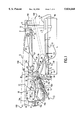
- FIG. 1 shows a cross-sectional view of a keyboard apparatus having a mass member in accordance with an embodiment of the present invention.
- FIGS. 2 (A) and (B) show a cross-sectional view taken along lines IIA--IIA in FIG. 1 and a cross-sectional view taken along lines IIB--IIB in FIG. 1, respectively.
- FIGS. 3 (A) and 3(B) show a cross-sectional view taken along lines IIIA--IIIA in FIG. 1 and a cross-sectional view taken along lines IIIB--IIIB in FIG. 1, respectively.
- FIGS. 4(A)-4(E) show metal sections for a mass member having different shapes of deformation in accordance with embodiments of the present invention.
- FIG. 5 schematically shows a prior art punching process in which metal sections for mass members are punched out from a sheet of metal.
- FIGS. 6 (A) and (B) schematically show a mass member manufacturing process in accordance with an embodiment of the present invention in which metal sections for mass members are formed from a bar of metal.
- FIG. 1 shows a cross-sectional view of a white key assembly of a keyboard apparatus in accordance with an embodiment of the present invention.
- FIGS. 2 (A) and 2(B) show a cross-sectional view taken along lines IIA--IIA in FIG. 1 and a cross-sectional view taken along lines IIB--IIB in FIG. 1, respectively.
- FIGS. 3 (A) and 3(B) show a cross-sectional view taken along lines IIIA--IIIA in FIG. 1 and a cross-sectional view taken along lines IIIB--IIIB in FIG. 1, respectively.
- a white key 1 has a pivot fulcrum section 2 formed adjacent a rear end section 2a of the white key 1.
- the white key 1 is mounted on a support member 3 so that the white key 1 is movable with respect to the support member 3.
- the pivot fulcrum section 2 of the white key 1 is supported at a fulcrum section 31 of the support member 3 in a manner that the white key 1 is movable about the pivot fulcrum section 2 with respect to the support member 3.
- a mass member 6 is disposed below the white key 1 and moves in association with movements of the white key 1.
- the mass member 6 generally includes a mass concentration section 4 and a resin section 5 integrally connected to the mass concentration section 4. It is noted that a mass member for a black key (not shown) has a similar structure as that of the mass member 6. Therefore, description for the mass member for the black key is omitted.
- the mass concentration section 4 is formed from a metal bar.
- the metal bar is made of an iron steel, or any one of appropriate metal materials, and is made by a drawing process.
- the metal bar has substantially the same cross-sectional area along its longitudinal axis as a result of the drawing process.
- the metal bar is cut into pieces, each having a predetermined length to define the mass concentration section 4.
- the length L of the metal concentration section 4 is generally about 20 cm or less. However, it is noted that the length L may be longer than 20 cm depending on types and sizes of particular keyboard apparatuses.
- the mass concentration section 4 has a rear end section 4a extending toward a rear side 100 of the keyboard apparatus, and is folded to define a folded section 4b as shown in FIG. 1.
- the weight of the rear end section 4a of the mass concentration section 4 can be increased.
- the center of gravity of the mass concentration section 4 shifts toward the rear end section 4a of the mass concentration section 4 due to the folded section 4b.
- the rotational moment of the mass member 6 that is generated upon depression of the white key 1 increases, and an improved, heavier key touch feeling is generated as described later in detail.
- the resin section 5 is fixed to a front base section 4c of the mass concentration section 4.
- the resin section 5 generally includes a front section 5f, an intermediate section 5g and a rear section 5h that are integrally formed together with a resin, such as for example, a polyacetal resin.
- a resin such as for example, a polyacetal resin.
- the front section 5f of the resin section 5 is coupled to the white key 1 and the rear section 5h is coupled to the mass concentration section 4.
- the resin section 5 includes a wall section 5a (see FIG. 2 (B)), and a reinforcement rib 5b provided in the wall section 5a.
- the resin section 5 may be connected to the mass concentration section 4 by any one of appropriate methods, such as, for example, resin outserting, pressurecoupling, gluing and the like.
- the resin section 5 is outserted over the front base section 4c of the mass concentration section 4 into a piece.
- the resin section 5 has a metal bar holding section 7 that is outserted over the front base section 4c of the mass concentration section 4.
- a bore 7a is provided in the metal bar holding section 7 by an appropriate method, for example, drilling or molding, and the front base section 4c of the mass concentration section 4 is inserted in the bore 7a (see FIG. 2 (B)) for connecting the resin section 5 with the mass concentration section 4.
- the connection between the front base section 4c of the mass concentration section 4 and the bore 7a of the metal bar holding section 7 is achieved by, for example, pressure coupling, gluing or the like.
- the metal bar supporting section 7 includes thin wall sections 8 and thick wall sections 8a.
- the thin wall sections 8 are provided on opposing sides of the mass concentration section 4 in a staggering fashion as shown in FIG. 2 (A).
- a stress may be generated due to a difference in thermal expansion (contraction) coefficient between the resin in the resin section 5 and the metal of the mass concentration section 4.
- the stress is concentrated in the thin wall sections 8, and the thick wall sections 8a have substantially reduced stress.
- generation of cracks in the thick wall sections 8a is substantially reduced. If cracks ever occur in the metal bar supporting section 7, the cracks would occur in the thin wall sections 8 of the metal bar supporting section 7, and the cracks are generally confined in the thin wall sections 8.
- Other thin wall sections 8b are provided on opposing sides of the mass concentration section 4 adjacent an end 4d of the mass concentration section 4. Burrs are likely formed at the end 4d of the mass concentration section 4 when the metal bar is cut to make the mass concentration section 4, and thus stresses may be generated at the burrs at the end 4d of the mass concentration section 4. The stresses generated at the end 4d of the mass concentration section 4 are generally concentrated in the thin wall sections 8b.
- the resin section 5 of the mass member 6 includes a pivot fulcrum receiving section 9 that pivotally engages a mass member fulcrum section 25 provided on the support member 3.
- the pivot fulcrum receiving section 9 of the resin section 5 includes a protrusion 10a that is inserted in a recess 10b provided at the mass member fulcrum section 25.
- a pressure spring 26 extends between the mass member 6 and the support member 2 and between the support member and the white key 1 for normally pressing the pivot fulcrum receiving section 9 against the mass member fulcrum section 25, and the pivot fulcrum section 2 against the fulcrum section 31, respectively.
- the pressure spring 26 may be formed from, for example, an elongated belt-like leaf spring. One end of the pressure spring 26 abuts against a retaining section 28 provided at the back side of the fulcrum receiving section 9 of the mass member 6. An intermediate section of the pressure spring 26 engages a step section 27 of the support member 3 for pressing the fulcrum receiving section 9 against the mass member fulcrum section 25. The other end P of the pressure spring 26 pushes the support section 2 of the white key 1 against the fulcrum section 31.
- the resin section 5 of the mass member 6 includes an actuator 11 formed in a piece.
- the actuator 11 depresses a touch response switch 12 mounted on a substrate 13 that is fixed to the underside of the support member 2 with bolts or the like (not shown).
- the touch response switch 12 includes pressure sections 11a and 11b that successively depress rubber cups 12a and 12b of the touch response switch 12. As a result, switch contacts (not shown) inside the rubber cups 12a and 12b are successively closed to provide a signal corresponding to a key depression speed.
- the support member 3 includes key guides 14a and 14b provided below the white key 1 adjacent a leading end 102 of the white key 1 and adjacent a central section 104 of the white key 1, respectively.
- the support member 3 includes a lower limit stopper 15a that abuts against the white key 1 adjacent the leading end 102 of the white key 1, and a stopper 15b that abuts against the white key 1 when the white key 1 is depressed with an excessive key depression force.
- a stopper 15c is provided on the support member 3 adjacent the pivot fulcrum section 2 of the white key 1 in the rear side 100 of the keyboard apparatus.
- the end section 4a of the mass concentration section 4 of the mass member 6 Upon depression of the white key 1 with an ordinary key depression force, the end section 4a of the mass concentration section 4 of the mass member 6 is moved in the direction shown by an arrow C shown in FIG. 1, and the folded section 4b of the mass concentration section 4 abuts against the stopper 15c, as shown in a dot and dash line in FIG. 1.
- the end section 4a the folded section 4b
- the stopper 15c functions to stop the movement of the mass member 6.
- the other stoppers 15a and 15b come in contact with the white key 1 only when the white key 1 is depressed with an excessive force greater than an ordinary key depression.
- the white key 1 pivots about the pivot supporting section 2 in the direction of an arrow A at the rear end of the white key 1, and the leading end 102 of the white key 1 moves in the direction of an arrow B.
- the lower edge of the white key 1 successively abuts against the stoppers 15b and 15a.
- the height of the stoppers 15a and 15b may be adjusted so that the white key 1 first comes in contact with the stopper 15a and then the stopper 15b.
- a coupling member 16 is provided at the lower surface of the key 1 at a position that is rearwardly receded from the leading end 102 of the white key 1.
- the coupling member 16 transmits a key depression force generated by the key depression operation from the white key 1 to the mass member 6, and also by a key releasing force from the mass member 6 to the white key 1.
- the coupling member 16 and the resin section 5 of the mass member 6 define a force transmission section 17.
- the force transmission section 17 is shown in detail in FIG. 3.
- the coupling member 16 has a protruding piece 16a in the shape of a letter L connected to the lower end of the coupling member 16 (see FIG. 1).
- the protruding piece 16a engages a lower portion of a connecting shaft 18.
- the connecting shaft 18 is preferably made of a flexible material.
- the connecting shaft 18 is formed from a relatively hard shaft and a flexible material wrapped around the hard shaft (not shown).
- the connecting shaft 18 is connected to the lower end portion of the coupling member 16 and is slidably held between an upper retaining member 19a and two lower retaining members 19b of the resin section 5 of the mass member 6.
- the connecting shaft 18 is removable from the coupling member 16.
- the lower retaining members 19b are longer than the upper key retaining member 19a and function as key connecting guides to facilitate the connection of the white key 1 to the mass member 6.
- the mass member 6 is first inserted into the support member 2, the connecting shaft 18 of the connecting member 16 is guided along the lower retaining members 19b of the mass member 6.
- the connecting member 16 and the mass member 6 are connected through the flexible connecting shaft 18.
- an impact that may be generated upon depression of the white key 1 is absorbed.
- a smooth connection between the connecting member 16 and the mass member 6 is achieved, with high mutual responsiveness and without rattles, and thus a key depression force is correctly transferred.
- the connecting shaft 18 of the connecting member 16 is slidably held between the upper retaining member 19a and the lower retaining members 19b, the force transmission section 17 transfers forces in both upward and downward direction.
- the connecting member 16 is linked to the mass member 6 in both upward and downward movements of the connecting member 16. Accordingly, even when the key 1 is rapidly depressed with a substantial force, the connecting member 16 remains linked to the mass member 6. As a result, unpleasant vibrations of the key 1 are substantially eliminated and the key touch feeling of the keyboard apparatus is improved.
- the resin section 5 of the mass member 6 has a rearwardly extending fall-out stop member 29 formed in a relatively rearward section of the resin section 5 adjacent the mass member fulcrum section 25.
- the fall-off stop member 29 abuts against an end section 30 provided in the key support member 3 to prevent the mass member 6 from falling off in the rearward direction (in the rightward direction in FIG. 1).
- the mass member 6 is rotated in a clockwise direction and then pushed downward. The mass member 6 then is downwardly moved to disengage the fall-off stop member 29 from the end section 30 of the key support member 3.
- the rear end section 4a of the mass concentration section 4 is folded to form the folded section 4b, as shown in FIG. 1.
- a metal bar member 40 is made by a drawing method, and may be wound into a coil as shown in FIG. 6 (A).
- the metal bar member 40 may be made of any one of appropriate metal materials or alloys, such as, for example, iron, stainless steel, and the like.
- FIG. 6 (B) one end of the straight metal bar member 40 is led into a metal bar cutting and bending apparatus 110.
- the metal bar cutting and bending apparatus 110 includes a work table 50 and a guide 51 for guiding the metal bar member 40 on the work table 50.
- the metal bar cutting and bending apparatus 110 also includes a table 130 that is movable in a lengthwise direction of the metal bar member 40 and a guide and pipe fixing member 131 fixed on the table 130. A stopper 32 is also fixed on the table 130 next to the guide and pipe fixing member 130.
- a first step the leading end of the metal bar member 40, that has passed the work table 50, is then guided by the guide and pipe fixing member 131 and is abutted against the stopper 32.
- the metal bar member 40 is cut by a cutter blade 33 of the metal bar cutting and bending apparatus 110 as shown by an arrow in FIG. 6 (B) just below the cutter blade 33.
- the cutter blade 33 moves in association with a push member 34 disposed above and outside of an end face 50a of the table 50.
- a third step after the cutter blade 33 cuts off a metal bar 4 from the metal bar member 40, the push member 34 that moves in association with the cutter blade 33 pushes down a folding section 4b of the metal bar 4 and bends the folding section 4b about an end corner T of the guide and pipe fixing member 131 to a position 4b'.
- the push member 34 and the cutter blade 35 are raised to an original position.
- a plunger 35 is moved from a stand-by position shown in FIG. 6 (B) to further push the folding section 4b to the left into a completely folded state as shown in FIG. 1.
- an auxiliary plunger 36 may be used for further upward bending.
- a leading end 4d of the metal bar 4 (that defines the mass concentration section 4) is pushed to the right by a plunger rod 32a that is slidable through the stopper 32. Concurrently with the motion of the plunger rod 32a, the table 130 is moved to the left.
- the metal bar 4 is released from the guide and pipe fixing member 131 and drops into a receiving container 38 that is positioned below the pipe member 131.
- burrs in the metal bar 4 Let us take a look at generation of burrs in the metal bar 4 during the above described steps. If burrs are ever generated, they occur at a lower cut edge 4c of the metal bar 4. Burrs at the lower cut edge 4c come inside as the folded section 4b is completely bent (at 180 degrees), therefore the burrs generated at the lower cut edge 4c do not come in contact with other sections of the keyboard apparatus, for example, the stopper 15c.
- the other end 4d is embedded in the resin section 5, and accordingly burrs at the other end 4d are embedded in the resin section 5.
- the metal bar holding section 7 of the resin section 5 includes thin wall sections 8b at the end 4d of the metal bar 4 to effectively confine cracks in the thin wall sections 8b in order to substantially eliminate total destruction of the resin section 5 due to cracks.
- the table 130 is moved when the bar member 4 is removed from the guide and pipe fixing member 131.
- the movement of the table 130 may be used to change the length of the folded section 4b of the metal bar 4.
- the table 130 may be stopped at different locations to change the length of the folded section 4b of the metal bar 4.
- the table 130 is moved to the left (or to the right), from a location shown in FIG. 6 (B), and then the cutting and bending works are performed.
- the metal bar (mass concentration section) 4 having the same nominal length L with a longer (or shorter) folded section 4b is created (see FIGS. 1 and 4 (D)).
- keyboard apparatus By using this cutting and bending method, a keyboard apparatus with individual keys or groups of keys having different counter forces is achieved. In other words, keyboard scaling is performed to change the key touch feeling of individual keys or groups of keys. Also, since the weight of the mass member 6 is concentrated adjacent the end section 4a of the mass member 6, a lighter and better key touch feeling, that is much closer to the key touch feeling provided by an acoustic grand piano, is obtained, compared with a conventional mass member having its weight generally evenly distributed along the mass member or centered about its center of rotation.
- the metal concentration sections 4 can also be made by a variety of other methods. Some of the methods for creating the metal concentration sections 4 will be described below with reference to FIGS. 4 (A) through 4 (E).
- FIG. 4 (A) shows a main portion of the mass concentration section 4 in which a header process is performed after cutting the metal bar 4. More particularly, after cutting the metal bar 4, the table 130 is moved to the left, and the right end of the cut metal bar 4 is hit by a mass member having a specified head shaped recess.
- FIG. 6 (C) For the convenience of explanation of the header process, see FIG. 6 (C).
- the header work is better performed, from the view point of dynamics, if a header apparatus (not shown) is vertically aligned with the cutting and bending apparatus 110.
- the cutting and bending apparatus 110 is turned 90 degrees so that the righthand side of the cutting and bending apparatus 110 shown in FIG. 6 (C) is positioned at a top, and the left-hand side of the cutting and bending apparatus 110 is positioned at a bottom.
- the header apparatus is placed over the cutting and bending apparatus 110 to hit the metal bar 4 from the top.
- FIG. 4 (B) shows a main portion of the metal bar (mass concentration section) 4 in accordance with an embodiment. After cutting off the metal bar 4, one end of the metal bar 4 is roll pressed to provide an irregular weight distribution in the mass concentration section 4.
- FIG. 4 (C) shows a main portion of the metal bar (mass concentration section) 4 in accordance with an embodiment. After cutting off the metal bar 4, one end of the metal bar 4 is pressed to provide an irregular weight distribution in the mass concentration section 4. In this embodiment, a wide area section S is positioned to abut the stopper 15c.
- dimensions l 1 and D 1 , of the metal bar 4 shown in FIG. 4 (A) are varied to perform a keyboard scaling for adjusting or changing the key touch feeling for each of the keys or each group of the keys.
- Dimensions l 2 and D 2 of the metal bar 4 shown in FIG. 4 (B) and dimensions l 3 and D 3 of the metal bar 4 shown in FIG. 4 (C) may be varied in a similar manner to perform a keyboard scaling for adjusting or changing the key touch feeling for each of the keys or each group of the keys.
- FIG. 4 (E) shows a metal bar 4 in which an end section 4b of the metal bar (mass concentration section) is bent at an angle ⁇ .
- the angle ⁇ may be varied for each of the keys or a group of the keys to provide a keyboard scaling for adjusting or changing the key touch feeling.
- a key stopper is not provided to directly stop the white key 1 upon depression of the white key 1.
- the mass member stopper 15c is provided not only to stop the mass member 6 but also to serve to stop the white key 1 upon depression of the white key 1.
- a good key stop feeling is achieved.
- the good key stop feeling further improves the improved key touch feeling of the keyboard apparatus.
- a mass member for a keyboard apparatus is formed from a metal bar section having a predetermined length and a resin section integrally connected to the metal bar section. Substantial portions of the mass member that are difficult to form by a metal material are formed from a resin.
- the resin section of a mass member includes a fulcrum section, a pressure spring retaining section at the fulcrum section, a force transmission section, a switch actuator section, guide sections for coupling a key to the mass member, and a fall-off prevention section for preventing the mass member from falling off from a support member of the keyboard apparatus.
- a mass concentration section of a mass member is made by a metal bar that is made by a rolling process or a drawing process.
- the resin section is connected to the mass concentration section by embedding one of the end sections of the mass concentration section in a part of the resin section.
- the mass concentration section is made from a cut metal bar
- the cut metal bar may have burrs at the end section that is covered by the resin. Since the generated burrs are limited to a very small area at the end section of the metal bar, generation of cracks caused by the burrs is confined in that small area, and generation of cracks in other areas of the resin section, particularly in those areas that cover the mass concentration section, is substantially eliminated.
- the mass member has an improved mechanical strength, reduced clatters and reduced noise due to the clatters.
- a portion of the mass concentration section is deformed by one of several deformation processes, such as, for example, a header process, a rolling press process, a press process and the like.
- a header process such as, for example, a header process, a rolling press process, a press process and the like.
- burrs on the mass concentration section are eliminated and the processed portion has a smoother surface. Therefore, when the processed portion is connected to the resin section, generation of cracks is substantially reduced.
- the processed portion is positioned to abut against a stopper for stopping the mass member, damage to the stopper is substantially reduced.
- the mass concentration section is deformed at an appropriate location, such as, for example, at an intermediate section or an end section opposite to the section that is connected to the resin section, by any one of the processes described above, the center of gravity of the mass member can be shifted to a desired position. Moreover, with a small deformation provided to mass concentration sections, a keyboard apparatus with a different key touch feeling is provided.
- the length of mass concentration sections is changed with respect to individual keys or groups of keys to perform keyboard scaling for adjusting or changing the key touch feeling for each of the individual keys or each group of the keys.
- the length of the mass concentration section can be changed by changing the length of the metal bar when the metal bar is cut.
- mass concentration sections may have the same length when they are cut in a cutting operation, and one end of each of the mass concentration sections may be compressed (or extended) after the cutting operation to change the length or the weight distribution of each of the mass concentration sections.
- a mass member has a resin section and a metal bar section (a mass concentration section).
- the resin section has a metal bar supporting section that is outserted over one end section of the metal bar.
- thin wall sections are formed in the metal bar supporting section.
- thin wall sections are formed at an end of the metal bar which is embedded in the resin section. Cracks may be generated by burrs that may be present at the end of the metal bar or by a bending force applied to the mass member. However, such cracks are substantially confined within the thin wall sections provided at the end of the metal bar and do not spread into other areas of the resin section.
Landscapes
- Physics & Mathematics (AREA)
- Engineering & Computer Science (AREA)
- Acoustics & Sound (AREA)
- Multimedia (AREA)
- Electrophonic Musical Instruments (AREA)
Applications Claiming Priority (2)
| Application Number | Priority Date | Filing Date | Title |
|---|---|---|---|
| JP7152839A JP2917863B2 (ja) | 1995-06-20 | 1995-06-20 | 電子楽器の鍵盤装置およびその質量体製造方法 |
| JP7-152839 | 1995-06-20 |
Publications (1)
| Publication Number | Publication Date |
|---|---|
| US5834668A true US5834668A (en) | 1998-11-10 |
Family
ID=15549266
Family Applications (1)
| Application Number | Title | Priority Date | Filing Date |
|---|---|---|---|
| US08/667,017 Expired - Lifetime US5834668A (en) | 1995-06-20 | 1996-06-19 | Keyboarding apparatus for electronic musical instrument with simplified mass member and method of making mass member |
Country Status (4)
| Country | Link |
|---|---|
| US (1) | US5834668A (ko) |
| JP (1) | JP2917863B2 (ko) |
| KR (1) | KR100215758B1 (ko) |
| CN (2) | CN100565666C (ko) |
Cited By (17)
| Publication number | Priority date | Publication date | Assignee | Title |
|---|---|---|---|---|
| US6051767A (en) * | 1996-12-16 | 2000-04-18 | Yamaha Corporation | Keyboard musical instrument having key inertia device |
| US6147289A (en) * | 1998-09-25 | 2000-11-14 | Yamaha Corporation | Keyboard assembly and method of manufacturing it |
| US20060070515A1 (en) * | 2004-09-28 | 2006-04-06 | Yamaha Corporation | Keyboard apparatus |
| EP1746572A2 (en) | 2005-07-21 | 2007-01-24 | Yamaha Corporation | Keyboard apparatus |
| EP1746573A2 (en) | 2005-07-21 | 2007-01-24 | Yamaha Corporation | Keyboard apparatus |
| US20070017356A1 (en) * | 2005-07-21 | 2007-01-25 | Yamaha Corporation | Keyboard apparatus |
| US20070022864A1 (en) * | 2003-09-12 | 2007-02-01 | Yamaha Corporation | Key structure and keyboard apparatus |
| US20070131099A1 (en) * | 2005-12-14 | 2007-06-14 | Yamaha Corporation | Keyboard apparatus of electronic musical instrument |
| US20080295671A1 (en) * | 2007-05-28 | 2008-12-04 | Yamaha Corporation | Electronic Musical Instrument Keyboard Apparatus |
| US20100071533A1 (en) * | 2008-09-25 | 2010-03-25 | Yamaha Corporation | Keyboard Device |
| US20100071532A1 (en) * | 2008-09-25 | 2010-03-25 | Yamaha Corporation | Keyboard Apparatus |
| US20100269665A1 (en) * | 2009-04-24 | 2010-10-28 | Steinway Musical Instruments, Inc. | Hammer Stoppers And Use Thereof In Pianos Playable In Acoustic And Silent Modes |
| US7825312B2 (en) | 2008-02-27 | 2010-11-02 | Steinway Musical Instruments, Inc. | Pianos playable in acoustic and silent modes |
| US8541673B2 (en) | 2009-04-24 | 2013-09-24 | Steinway Musical Instruments, Inc. | Hammer stoppers for pianos having acoustic and silent modes |
| US20150269914A1 (en) * | 2014-03-20 | 2015-09-24 | Casio Computer Co., Ltd. | Keyboard device and keyboard instrument |
| US10710327B2 (en) | 2017-12-01 | 2020-07-14 | The Boeing Company | Methods for making composite parts from stacked partially cured sublaminate units |
| US11538444B2 (en) | 2020-12-25 | 2022-12-27 | Roland Corporation | Keyboard apparatus and key guiding method |
Families Citing this family (5)
| Publication number | Priority date | Publication date | Assignee | Title |
|---|---|---|---|---|
| JP3753645B2 (ja) * | 2001-10-16 | 2006-03-08 | 株式会社河合楽器製作所 | 鍵盤 |
| JP4293040B2 (ja) * | 2003-09-12 | 2009-07-08 | ヤマハ株式会社 | 鍵構造体 |
| JP6024996B2 (ja) * | 2014-03-20 | 2016-11-16 | カシオ計算機株式会社 | 鍵盤装置および鍵盤楽器 |
| JP6540147B2 (ja) * | 2015-03-25 | 2019-07-10 | ヤマハ株式会社 | サポートアセンブリおよび鍵盤装置 |
| JP6682944B2 (ja) * | 2016-03-25 | 2020-04-15 | ヤマハ株式会社 | 鍵盤装置及び電子鍵盤楽器 |
Citations (2)
| Publication number | Priority date | Publication date | Assignee | Title |
|---|---|---|---|---|
| US4901614A (en) * | 1986-10-06 | 1990-02-20 | Yamaha Corporation | Keyboard apparatus of electronic musical instrument |
| US4901613A (en) * | 1988-10-24 | 1990-02-20 | Carlton Raymond R | Drive link for saw chain |
-
1995
- 1995-06-20 JP JP7152839A patent/JP2917863B2/ja not_active Expired - Fee Related
-
1996
- 1996-03-22 KR KR1019960007986A patent/KR100215758B1/ko not_active IP Right Cessation
- 1996-06-18 CN CNB200410004160XA patent/CN100565666C/zh not_active Expired - Lifetime
- 1996-06-18 CN CNB961063483A patent/CN1163863C/zh not_active Expired - Lifetime
- 1996-06-19 US US08/667,017 patent/US5834668A/en not_active Expired - Lifetime
Patent Citations (2)
| Publication number | Priority date | Publication date | Assignee | Title |
|---|---|---|---|---|
| US4901614A (en) * | 1986-10-06 | 1990-02-20 | Yamaha Corporation | Keyboard apparatus of electronic musical instrument |
| US4901613A (en) * | 1988-10-24 | 1990-02-20 | Carlton Raymond R | Drive link for saw chain |
Cited By (36)
| Publication number | Priority date | Publication date | Assignee | Title |
|---|---|---|---|---|
| US6051767A (en) * | 1996-12-16 | 2000-04-18 | Yamaha Corporation | Keyboard musical instrument having key inertia device |
| US6147289A (en) * | 1998-09-25 | 2000-11-14 | Yamaha Corporation | Keyboard assembly and method of manufacturing it |
| US20070022864A1 (en) * | 2003-09-12 | 2007-02-01 | Yamaha Corporation | Key structure and keyboard apparatus |
| US7652207B2 (en) | 2003-09-12 | 2010-01-26 | Yamaha Corporation | Key structure and keyboard apparatus |
| US7541532B2 (en) * | 2003-09-12 | 2009-06-02 | Yamaha Corporation | Key structure and keyboard apparatus |
| US20080210079A1 (en) * | 2003-09-12 | 2008-09-04 | Yamaha Corporation | Key structure and keyboard apparatus |
| US20060070515A1 (en) * | 2004-09-28 | 2006-04-06 | Yamaha Corporation | Keyboard apparatus |
| US7402741B2 (en) * | 2004-09-28 | 2008-07-22 | Yamaha Corporation | Keyboard apparatus |
| US7332663B2 (en) | 2005-07-21 | 2008-02-19 | Yamaha Corporation | Keyboard apparatus |
| CN1901038B (zh) * | 2005-07-21 | 2010-06-09 | 雅马哈株式会社 | 键盘装置 |
| US7365259B2 (en) * | 2005-07-21 | 2008-04-29 | Yamaha Corporation | Keyboard apparatus |
| US20070017356A1 (en) * | 2005-07-21 | 2007-01-25 | Yamaha Corporation | Keyboard apparatus |
| US20070017343A1 (en) * | 2005-07-21 | 2007-01-25 | Yamaha Corporation | Keyboard apparatus |
| US20070017341A1 (en) * | 2005-07-21 | 2007-01-25 | Yamaha Corporation | Keyboard apparatus |
| US7465863B2 (en) | 2005-07-21 | 2008-12-16 | Yamaha Corporation | Keyboard apparatus |
| EP1746573A2 (en) | 2005-07-21 | 2007-01-24 | Yamaha Corporation | Keyboard apparatus |
| EP1746572A2 (en) | 2005-07-21 | 2007-01-24 | Yamaha Corporation | Keyboard apparatus |
| CN1901036B (zh) * | 2005-07-21 | 2010-08-18 | 雅马哈株式会社 | 键盘装置 |
| US20070131099A1 (en) * | 2005-12-14 | 2007-06-14 | Yamaha Corporation | Keyboard apparatus of electronic musical instrument |
| US7750231B2 (en) * | 2005-12-14 | 2010-07-06 | Yamaha Corporation | Keyboard apparatus of electronic musical instrument |
| US7858863B2 (en) * | 2007-05-28 | 2010-12-28 | Yamaha Corporation | Electronic musical instrument keyboard apparatus |
| US20080295671A1 (en) * | 2007-05-28 | 2008-12-04 | Yamaha Corporation | Electronic Musical Instrument Keyboard Apparatus |
| EP1998318A3 (en) * | 2007-05-28 | 2010-12-22 | Yamaha Corporation | Electronic musical instrument keyboard apparatus |
| US7825312B2 (en) | 2008-02-27 | 2010-11-02 | Steinway Musical Instruments, Inc. | Pianos playable in acoustic and silent modes |
| US8158876B2 (en) | 2008-09-25 | 2012-04-17 | Yamaha Corporation | Keyboard apparatus |
| US20100071533A1 (en) * | 2008-09-25 | 2010-03-25 | Yamaha Corporation | Keyboard Device |
| US20100071532A1 (en) * | 2008-09-25 | 2010-03-25 | Yamaha Corporation | Keyboard Apparatus |
| US7923619B2 (en) * | 2008-09-25 | 2011-04-12 | Yamaha Corporation | Keyboard device |
| EP2169661A1 (en) * | 2008-09-25 | 2010-03-31 | Yamaha Corporation | Keyboard instrument |
| US20100269665A1 (en) * | 2009-04-24 | 2010-10-28 | Steinway Musical Instruments, Inc. | Hammer Stoppers And Use Thereof In Pianos Playable In Acoustic And Silent Modes |
| US8148620B2 (en) | 2009-04-24 | 2012-04-03 | Steinway Musical Instruments, Inc. | Hammer stoppers and use thereof in pianos playable in acoustic and silent modes |
| US8541673B2 (en) | 2009-04-24 | 2013-09-24 | Steinway Musical Instruments, Inc. | Hammer stoppers for pianos having acoustic and silent modes |
| US20150269914A1 (en) * | 2014-03-20 | 2015-09-24 | Casio Computer Co., Ltd. | Keyboard device and keyboard instrument |
| US9495940B2 (en) * | 2014-03-20 | 2016-11-15 | Casio Computer Co., Ltd. | Keyboard device and keyboard instrument |
| US10710327B2 (en) | 2017-12-01 | 2020-07-14 | The Boeing Company | Methods for making composite parts from stacked partially cured sublaminate units |
| US11538444B2 (en) | 2020-12-25 | 2022-12-27 | Roland Corporation | Keyboard apparatus and key guiding method |
Also Published As
| Publication number | Publication date |
|---|---|
| CN100565666C (zh) | 2009-12-02 |
| JP2917863B2 (ja) | 1999-07-12 |
| CN1161526A (zh) | 1997-10-08 |
| KR100215758B1 (ko) | 1999-08-16 |
| CN1163863C (zh) | 2004-08-25 |
| JPH096329A (ja) | 1997-01-10 |
| CN1532805A (zh) | 2004-09-29 |
| KR970002840A (ko) | 1997-01-28 |
Similar Documents
| Publication | Publication Date | Title |
|---|---|---|
| US5834668A (en) | Keyboarding apparatus for electronic musical instrument with simplified mass member and method of making mass member | |
| US6995308B2 (en) | Electric keyboard assembly and method of manufacturing weight members provided in keyboard assembly | |
| JP2008304652A (ja) | 電子楽器の鍵盤装置 | |
| US5249497A (en) | Keyborad apparatus for electronic musical instrument | |
| JP4989864B2 (ja) | ピアノのアクション | |
| US5243125A (en) | Keyboard apparatus for electronic musical instrument having cooperating jacks and hammers | |
| CN110875027A (zh) | 用于电子键盘乐器的键盘装置和用于键盘乐器的键架前部 | |
| EP1450347B1 (en) | Keyboard musical instrument equipped with automatic top board spacer | |
| US5932825A (en) | Keyboard apparatus with white keys and black keys having substantially the same action members | |
| EP1152391B1 (en) | Damper formed of powder-containing synthetic resin and keyboard musical instrument equipped with the same | |
| US5079985A (en) | Keyboard apparatus for electronic keyboard musical instrument | |
| US4119008A (en) | Means for improving the repetition characteristics of an upright piano action | |
| EP1818908B1 (en) | Jack motion-restricting device for upright piano | |
| JPH1049166A (ja) | 電子楽器の鍵盤装置 | |
| US5945617A (en) | Piano keyboard device including improved support chassis and optional action simulation mechanism, and a method of assembling thereof | |
| JP2007108661A (ja) | アップライトピアノのアクション | |
| JP3891440B2 (ja) | 鍵盤装置 | |
| JP3624786B2 (ja) | 鍵盤装置 | |
| US4924742A (en) | Mechanical keyboard instrument with pedal mechanisms | |
| JP4769445B2 (ja) | アップライトピアノのアクション | |
| EP3073483B1 (en) | Support assembly and keyboard apparatus | |
| JP3591579B2 (ja) | 鍵盤装置 | |
| JP3932651B2 (ja) | 自動演奏鍵盤楽器のペダル構造 | |
| JP3938157B2 (ja) | 鍵盤装置 | |
| US20240212651A1 (en) | Keyboard device for keyboard instrument |
Legal Events
| Date | Code | Title | Description |
|---|---|---|---|
| AS | Assignment |
Owner name: YAMAHA CORPORATION, JAPAN Free format text: ASSIGNMENT OF ASSIGNORS INTEREST;ASSIGNORS:SHINJI, KUMANO;SATO, TSUYOSHI;REEL/FRAME:008145/0182 Effective date: 19960826 |
|
| STCF | Information on status: patent grant |
Free format text: PATENTED CASE |
|
| FEPP | Fee payment procedure |
Free format text: PAYOR NUMBER ASSIGNED (ORIGINAL EVENT CODE: ASPN); ENTITY STATUS OF PATENT OWNER: LARGE ENTITY |
|
| FPAY | Fee payment |
Year of fee payment: 4 |
|
| FPAY | Fee payment |
Year of fee payment: 8 |
|
| FPAY | Fee payment |
Year of fee payment: 12 |