US5820539A - Device and method for continuous plaiting of web-shaped material - Google Patents
Device and method for continuous plaiting of web-shaped material Download PDFInfo
- Publication number
- US5820539A US5820539A US08/730,324 US73032496A US5820539A US 5820539 A US5820539 A US 5820539A US 73032496 A US73032496 A US 73032496A US 5820539 A US5820539 A US 5820539A
- Authority
- US
- United States
- Prior art keywords
- plaiting
- auxiliary
- depositing means
- auxiliary depositing
- plaiting table
- Prior art date
- Legal status (The legal status is an assumption and is not a legal conclusion. Google has not performed a legal analysis and makes no representation as to the accuracy of the status listed.)
- Expired - Fee Related
Links
Images


Classifications
-
- B—PERFORMING OPERATIONS; TRANSPORTING
- B65—CONVEYING; PACKING; STORING; HANDLING THIN OR FILAMENTARY MATERIAL
- B65H—HANDLING THIN OR FILAMENTARY MATERIAL, e.g. SHEETS, WEBS, CABLES
- B65H45/00—Folding thin material
- B65H45/02—Folding limp material without application of pressure to define or form crease lines
- B65H45/06—Folding webs
- B65H45/10—Folding webs transversely
- B65H45/101—Folding webs transversely in combination with laying, i.e. forming a zig-zag pile
- B65H45/107—Folding webs transversely in combination with laying, i.e. forming a zig-zag pile by means of swinging or reciprocating guide bars
-
- B—PERFORMING OPERATIONS; TRANSPORTING
- B65—CONVEYING; PACKING; STORING; HANDLING THIN OR FILAMENTARY MATERIAL
- B65H—HANDLING THIN OR FILAMENTARY MATERIAL, e.g. SHEETS, WEBS, CABLES
- B65H31/00—Pile receivers
- B65H31/32—Auxiliary devices for receiving articles during removal of a completed pile
Definitions
- the present invention relates to a method and device for continuous plaiting of web-shaped material.
- plait is understood to be the zigzag folding and laying down of web-shaped material onto trays, pallets or transport trolleys.
- the material is lead past an arm moving to and fro like a pendulum, said arm laying the material down on a base in a zigzag shape.
- a slidable or travelling plaiting table is generally used, for example in the form of a trolley.
- the base is removed, the stacked material is unloaded, and the empty plaiting table is returned to a position beneath the plaiting station.
- Arrangements of the prior art all have the drawback, however, that the machines operating in the line upstream of the plaiting station must be brought to rest during the unloading procedure. Because of the constant interruptions, productivity of the machines prior to the plaiting station will be greatly impaired. On the one hand, the machines will not be producing for a relatively long period, and on the other hand frequent stopping both complicates the construction and reduces the life span of the machines.
- EP 116 100 discloses a device for packaging of flat-shaped material. A material web is cut through by a blade, a temporary backing surface being slid beneath the material web by the blade at the same time, so that interruption of the working sequence is not required. Also with this device, there are problems when the deposited material is laid on the plaiting table from the temporary backing.
- the purpose of the present invention is to avoid the disadvantages of the state of the art, and in particular to create a device for the continuous plaiting of web-shaped material, said device dispensing with the need for stopping the machines in the line upstream of the plaiting station and enabling regular plaiting.
- a further purpose of the present invention is to create a method for the continuous plaiting of web-shaped material, said method dispensing with the need for stopping the machines in the line upstream of the plaiting station and enabling uniform plaiting.
- the device according to the present invention for the plaiting of web-shaped material comprises a plaiting table and a plaiting arm arranged above said plaiting table, and additionally possesses additional auxiliary depositing means for continuous plaiting.
- the auxiliary depositing means can be slid between the plaiting arm and the plaiting table in a direction of insertion and are provided with an insertion face.
- insertion face is understood to be that component of the auxiliary depositing means that is inserted first between the plaiting arm and the plaiting table.
- the auxiliary depositing means are provided with at least one recess extending from said insertion face in the direction of insertion. Due to these recesses, the contact surface between the auxiliary depositing means and the stacked material can be reduced.
- the auxiliary depositing means comprise a rack.
- the recesses are in this case formed by the intermediate space between the individual rods of the rack. It is also conceivable, however, to employ flat auxiliary depositing means possessing only two or three recesses extending in the direction of insertion.
- the plaiting table is provided with upwardly pointing supporting elements formed to complement the recesses in the auxiliary depositing means so that said supporting elements can penetrate said recesses.
- said plaiting table Prior to transfer of the plaited material by the auxiliary depositing means to the plaiting table, said plaiting table can be raised (or the auxiliary depositing means can be lowered), so that the supporting elements penetrate the recesses in the auxiliary depositing means and support the plaited material.
- the auxiliary depositing means can then be simply pulled out between the stack of material and the plaiting table, since said auxiliary depositing means no longer make direct contact with the web of material.
- the number and shape of the recesses is of little significance to the functioning of the device according to the present invention; essential is that the recesses extend from the insertion face of the auxiliary depositing means in the direction of insertion.
- the supporting elements of a particularly advantageous plaiting table are arranged to be mobile.
- the supporting elements can, for example, be formed as circulating belts. In order to unload the plaiting table, said belts can be moved so that the stack of material can be brought from the plaiting table to an adjacent depositing position.
- the supporting elements fulfil a function not only during transfer of the material from the auxiliary depositing means but also during transfer of the material for further working, such as packaging or transport.
- the web-shaped material is led by the plaiting arm, said plaiting arm being able to move to and fro like a pendulum.
- the web-shaped material is stacked in layers in a zigzag way on the plaiting table.
- the auxiliary depositing means are inserted between the stack of material and the plaiting arm.
- the auxiliary depositing means assume the function of the plaiting table for a certain period.
- the plaiting table with the stack of material can therefore be removed from the plaiting station and unloaded without the need for interruption of the plaiting sequence. After emptying of the plaiting table, said table can be repositioned directly below the auxiliary depositing means and the new stack of material, deposited on said the auxiliary depositing means, can be transferred to the plaiting table.
- the plaiting device also possesses a cutting device by which means the plaited material can be separated from the subsequent web prior to unloading of the plaiting table.
- a particularly advantageous embodiment will result if the plaiting table and/or the auxiliary depositing means are arranged to be height-adjustable. As a result, the surface of the plaited stack of material can be maintained at the same height relative to the plaiting arm at all times. With advantage, both plaiting table and auxiliary depositing means are moved downwards during plaiting.
- the plaiting device possesses a feed device for covering the auxiliary depositing means with a flat underlay.
- the auxiliary depositing means especially a rack, are covered with a flat underlay by the feed device.
- the underlay can preferably comprise cardboard. With said feed unit, cardboard can also be laid upon the upper side of the plaited stack of material. This preferably ensues shortly after the auxiliary depositing means has assumed the function of the plaiting table.
- a particularly advantageous embodiment of the invention will result if the plaiting table is arranged to be slidable from a plaiting position into an unloading position.
- the method according to the present invention for continuous plaiting of web-shaped material is characterized in that the plaiting table is replaced by the auxiliary depositing means during unloading.
- the web-shaped material is laid in the usual way on a plaiting table.
- the auxiliary depositing means assumes the function of the plaiting table.
- the plaiting table can be removed, along with the stacked material, from the plaiting station without interruption of the plaiting sequence, and thus without stopping the machines in the line upstream of the plaiting station.
- the material is plaited on the auxiliary depositing means.
- the plaiting table After unloading of the material, the plaiting table is once again returned into its original position and takes over the stack which was being stacked on the auxiliary depositing means. In this way, a continuous plaiting cycle will arise that dispenses with the need for stopping the machines upstream in the line.
- the auxiliary depositing means possesses recesses extending from the insert face in the direction of insertion. Apart from that, the auxiliary depositing means possesses at least one supporting element extending upwards.
- the plaiting table is raised and/or the auxiliary depositing means is lowered so that the supporting elements of the plaiting table penetrate the recesses of the auxiliary depositing means from below and raise the material laid upon the auxiliary depositing means. With that, the auxiliary depositing means is relieved of the plaited material and can simply be pulled out laterally between the supporting elements.
- the stacked material is separated from the subsequent web shortly before the plaiting table is replaced in its function by the auxiliary depositing means.
- a individual stack is thus always initially stacked on the auxiliary depositing means, and subsequently transferred to the plaiting table.
- a particularly advantageous embodiment of the method will result if the plaiting table is lowered during plaiting so that the upper level of the stack of plaited material is maintained at a constant height.
- the plaiting table is lowered during plaiting, it is advantageous to also lower the auxiliary depositing means during plaiting.
- the auxiliary depositing means Prior to assuming the function of the plaiting table, the auxiliary depositing means will be located slightly above the upper surface of the stack of material on the plaiting table.
- the auxiliary depositing means are likewise lowered in such a way that the upper level of the stack laid upon said auxiliary depositing means remains at a constant height.
- the plaiting table is positioned in such a way that said table comes to lie within the auxiliary depositing means from beneath. Accordingly, transfer of the plaited stack from the auxiliary depositing means to the plaiting table will prove to be particularly simple.
- the auxiliary depositing means are inserted between the plaiting arm and the upper level of the stack on the plaiting table, prior to unloading of the plaiting table.
- the auxiliary depositing means are covered with a flat and stable underlay prior to assuming the function of a plaiting table.
- the web-shaped material is thus not plaited directly onto the auxiliary depositing means, but on an underlay lying upon said auxiliary depositing means.
- the stacked material remains lying on the firm underlay on the plaiting table, also during transfer onto the plaiting table and during the unloading sequence from said plaiting table.
- Use of this type of a firm underlay will achieve a constantly flat-lying lowermost layer of the stacked material, also when the auxiliary depositing means are withdrawn from beneath the stack.
- the firm underlay offers protection from folding, wrinkling or tearing, and also soiling by the auxiliary depositing means.
- FIG. 1 A schematic representation of a device according to the present invention at commencement of the plaiting sequence
- FIG. 2 a schematic representation of a device according to the present invention during plaiting onto the auxiliary depositing means
- FIG. 3 a schematic representation of the unloading sequence from the plaiting table
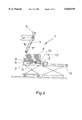
- FIG. 4 a schematic representation of the device shortly before transfer of the material stack from the auxiliary depositing means to the plaiting table
- FIG. 5 a schematic representation of the device according to the present invention during the normal plaiting sequence
- FIGS. 6a to 6c plan views of various embodiments of auxiliary depositing means according to the present invention.
- FIG. 7 a schematic representation of the plaiting table and auxiliary depositing means of a particularly preferred embodiment
- FIGS. 8a to 8c schematic representations of a plaiting table of a further embodiment
- FIG. 9 a frontal view of a device according to the present invention.
- FIG. 1 shows a device 1 for plaiting of web-shaped material onto a plaiting table 2.
- the device 1 possesses a pendulum-like oscillating plaiting arm 3 for laying the web-shaped material in zigzag-shaped layers on the plaiting table 2.
- the material laid in a zigzag-shape forms a material stack 4.
- the device 1 possesses a cutting device 6 for separation of the material stack 4 from the subsequent web-shaped material, as well as auxiliary depositing means 5.
- the auxiliary depositing means 5 are mounted on a height-adjustable holder 10 so as to be able to slide horizontally.
- the auxiliary depositing means possess recesses 15 (only schematically suggested in FIGS. 1 to 5), said recesses extending from the insertion face S of the auxiliary depositing means 5 in the insertion direction R.
- the plaiting table 2 is also arranged to be height-adjustable.
- the auxiliary depositing means 5 are able to be inserted between the upper level of the material stack 4 and the plaiting arm 3.
- the device 1 possesses a feed device 11 for covering the auxiliary depositing means 5 with flat, stable underlays 8.
- FIG. 1 portrays the initial step of a plaiting cycle.
- the term "plaiting cycle” is here understood to be the laying in folds of a material stack 4 on the plaiting table 2, with subsequent emptying of said plaiting table 2.
- the web-shaped material is laid with the plaiting arm 3 in zigzag shapes on the plaiting table 2, while the plaiting table 2 is lowered.
- the lowering speed is selected in such a way that the upper level of the plaited material stack 4 remains at a constant height relative to the plaiting arm 3.
- the auxiliary depositing means are covered with stable, flat underlays by a feed device.
- FIG. 2 shows the device according to FIG. 1, shortly after the height H of the stack 4 laid on the plaiting table 2 has reached a desired value.
- the auxiliary depositing means 5 are inserted horizontally between the material stack 4 and the plaiting arm 3, shortly after the material stack 4 has been separated with a cutting device 6.
- the subsequent material web is now laid down in a further material stack 4' onto the auxiliary depositing means 5, respectively on the underlay 8 lying upon said auxiliary depositing means.
- the height-adjustable holder 10, to which the auxiliary depositing means are attached, is lowered in such a way that the upper level 13' of the material stack 4' laid upon the auxiliary means 5 remains at a constant height relative to the plaiting arm 3.
- the plaiting table 2 with the material stack 4 is moved from a plaiting position T into an unloading position E (see FIG. 3).
- the plaiting table 2 can be mounted on a roller trolley 12. It is also conceivable, however, to mount the plaiting table 2 on rails or on a conveyor belt.
- the auxiliary means 5 assumes the function of the plaiting table, the upper level 13 of the material stack 4 can be covered with a flat support 8' of cardboard. The material stack is thus limited on both sides.
- FIG. 3 schematically shows how the material stack 4, together with the underlay 8, is removed from the plaiting table 2 while the next material stack 4' is laid on the auxiliary depositing means 5.
- the plaiting table 2 is returned to its original position.
- FIG. 4 shows how the plaiting table is positioned directly into the auxiliary depositing means 5.
- the auxiliary depositing means 5 are pulled out under the underlay 8, by which means the material stack 4' together with the underlay 8 is transferred to the plaiting table 2.
- the auxiliary depositing means 5 is returned to its original position, and the web-shaped material is plaited onto the plaiting table 2.
- the auxiliary depositing means 5 is once again brought to a position corresponding to that shown in FIG. 1.
- auxiliary depositing means 5 assumes the function of the plaiting table during unloading of said plaiting table, uninterrupted plaiting is possible.
- FIG. 6a shows a plan view of the auxiliary depositing means 5 according to the present invention, said auxiliary depositing means being formed as a rack 7. Intermediate spaces 15 are present between the individual rods of the rack through which supporting elements 16 (see FIG. 7) of a plaiting table 2 can be inserted from beneath and raised. The recesses 15 extend from the face S of the auxiliary depositing means 5 in the direction of insertion R.
- FIG. 6b shows a modified embodiment of the auxiliary depositing means according to the present invention.
- the auxiliary depositing means 5 are formed as a plate 22 possessing recesses 15.
- the recesses 15 extend from the face S of the plate 22 in the direction of insertion R.
- FIG. 6c shows a plate 22 with a single recess 15. Basically, any number of recesses is possible. In order to ensure the best possible weight distribution of the material laid onto the auxiliary depositing means 5 as well as a uniform transfer of the material from the auxiliary depositing means to the plaiting table, a greater number of recesses, for example five to ten, is recommended.
- FIG. 7 schematically shows a plaiting table 2 with an auxiliary depositing means 5 according to the present invention in the form of a rack 7.
- the rack 7 possesses recesses 15 extending from the face S in the direction of insertion R.
- the plaiting table 2 possesses supporting elements 16 protruding from its surface.
- the supporting elements 16 form a support surface 19 for the plaited material.
- the plaiting table 2 is raised and/or the auxiliary depositing means 5 is lowered, so that the supporting elements 16 of the plaiting table 2 penetrate the intermediate spaces 15 of the auxiliary depositing means 5.
- the supporting elements 16 raise the material web laid on the auxiliary depositing means 5 so that said material web lies upon the support surface 19. Subsequently, the rack 7 which is now relieved of the material stack can be withdrawn laterally between the supporting elements 16.
- this embodiment can be used in combination with an underlay 8. In this case, not the plaited and deposited material stack, but rather the underlay, will be raised by the supporting elements 16.
- FIGS. 8a to 8c show a further embodiment, wherein the supporting elements 16 comprise two belts mounted to move on rollers. Similar to FIG. 7, a plaited stack of material 4 is transferred from the rack 7 onto the support surface 19 formed by the supporting elements 16. The support surface 19 is essentially formed by the belt 18.
- the particular advantage of this arrangement is that the material stack 4 (optionally on an underlay 8 placed upon the auxiliary depositing means 5 prior to the plaiting sequence) is simply removed from the plaiting table 2. It is sufficient to move the band 18 forming the support surface 19 in such a way that the material stack 4 is slid laterally from the plaiting table. It is conceivable, for example, to transfer the material stack 4 from the plaiting table 2 to a packaging station, into storage, or onto a transport means.
- FIG. 9 schematically shows the frontal view of the embodiment according to FIG. 7 during transfer of the material stack 4 from the rack 7 to the plaiting table 2.
- the supporting elements 16 of the plaiting table 2 are so arranged that they penetrate the recesses 15 between the individual arms of the rack 7.
- the material stack 4 is raised by the supporting elements 16 and lies on the support surface formed by the supporting elements 16.
- the rack 7 is thus relieved, and can simply be pulled out between the plaiting table 2 and the plaited and deposited material stack 4 (or optionally the underlay 8).
- FIG. 9 such an underlay is likewise schematically shown.
- the underlay 8 is, however, not absolutely essential for correct functioning of the device or method according to the present invention.
Landscapes
- Engineering & Computer Science (AREA)
- Mechanical Engineering (AREA)
- Pile Receivers (AREA)
Applications Claiming Priority (2)
| Application Number | Priority Date | Filing Date | Title |
|---|---|---|---|
| CH288995 | 1995-10-12 | ||
| CH02889/95 | 1995-10-12 |
Publications (1)
| Publication Number | Publication Date |
|---|---|
| US5820539A true US5820539A (en) | 1998-10-13 |
Family
ID=4243882
Family Applications (1)
| Application Number | Title | Priority Date | Filing Date |
|---|---|---|---|
| US08/730,324 Expired - Fee Related US5820539A (en) | 1995-10-12 | 1996-10-09 | Device and method for continuous plaiting of web-shaped material |
Country Status (2)
| Country | Link |
|---|---|
| US (1) | US5820539A (de) |
| EP (1) | EP0768261A1 (de) |
Cited By (17)
| Publication number | Priority date | Publication date | Assignee | Title |
|---|---|---|---|---|
| US6006638A (en) * | 1998-03-02 | 1999-12-28 | Kendor Steel Rule Die, Inc. | Automated sheet metal blanking apparatus |
| US6209288B1 (en) * | 1996-10-25 | 2001-04-03 | Kortec Gmbh | Device and process for laying band or strip material |
| US6341771B1 (en) * | 2000-01-25 | 2002-01-29 | The Goodyear Tire & Rubber Company | Method of stacking strips of flexible material |
| WO2003051753A1 (en) * | 2001-12-13 | 2003-06-26 | General Binding Corporation | Transportation system for sheet delivery between sheet or sheet stack processing equipment |
| US20040071539A1 (en) * | 2002-07-03 | 2004-04-15 | Anater Raymond J. | Automated container management system |
| US20040147384A1 (en) * | 2001-05-25 | 2004-07-29 | Christian Lenk | Device and method for folding a flexible material web |
| US20050042072A1 (en) * | 2002-12-13 | 2005-02-24 | Samuel Amdahl | Transportation system for sheet delivery between sheet or sheet stack processing equipment |
| US6913569B1 (en) * | 1998-06-29 | 2005-07-05 | Bentle Products Ag | Packed tapes as well as methods and an assembly for packing said tapes |
| US20050193928A1 (en) * | 2004-02-23 | 2005-09-08 | General Binding Corporation | Universal sled for adaptation of existing sheet stack processing machine for use with sheet handling system |
| US6971837B1 (en) * | 2003-12-31 | 2005-12-06 | Honda Motor Co., Ltd. | Stack handling and handwork table |
| US20070031219A1 (en) * | 2005-07-21 | 2007-02-08 | Axel Besch | Load receiving means for single or multiple deep storage and retrieval of objects into and from a shelf |
| US7402130B1 (en) * | 2006-09-29 | 2008-07-22 | Roll Systems, Inc. | System and method for folding and handling stacks of continuous web |
| US20090163341A1 (en) * | 2006-03-04 | 2009-06-25 | Rosink Gmbh + Co. Kg Maschinenfabrik | Device for Laying Web Material |
| US20120288354A1 (en) * | 2011-05-11 | 2012-11-15 | Xerox Corporation | Load transferring mechanism in a sheet-feeding system |
| US8746689B1 (en) * | 2013-01-31 | 2014-06-10 | Xerox Corporation | Systems, apparatus, and methods for automatic stacking support configuration and unload configuration useful for substrate stacker support in printing systems |
| CN105236191A (zh) * | 2015-11-19 | 2016-01-13 | 青岛佳友精密机械有限公司 | 连续纸板堆码机 |
| US20220089400A1 (en) * | 2019-02-26 | 2022-03-24 | Bobst Lyon | Station and method for receiving sheet elements for a machine for manufacturing packaging |
Families Citing this family (1)
| Publication number | Priority date | Publication date | Assignee | Title |
|---|---|---|---|---|
| CN102677377B (zh) * | 2012-05-15 | 2013-09-11 | 绍兴县鲁迅中学柯桥校区 | 一种剑杆织机用的简易挂码机 |
Citations (20)
| Publication number | Priority date | Publication date | Assignee | Title |
|---|---|---|---|---|
| US4162649A (en) * | 1977-05-18 | 1979-07-31 | Wiggins Teape Limited | Sheet stack divider |
| US4359218A (en) * | 1980-06-23 | 1982-11-16 | Beloit Corporation | Continuous sheet collection and discharge system |
| US4406650A (en) * | 1980-04-10 | 1983-09-27 | Jos. Hunkeler Ag Fabrik Fur Graphische Maschinen | Apparatus for forming individual stacks from an endless web |
| DE3304673A1 (de) * | 1983-02-11 | 1984-08-16 | Jagenberg AG, 4000 Düsseldorf | Verfahren beim bogenstapeln |
| EP0116100A1 (de) * | 1981-11-27 | 1984-08-22 | Luciano Meschi | Apparat zum Aufnehmen, Verpacken und Weiterleiten von blattförmigem Material |
| US4673382A (en) * | 1985-01-23 | 1987-06-16 | Bielomatik Leuze Gmbh & Co. | Apparatus for forming folded stacks from a web |
| US4778165A (en) * | 1986-04-30 | 1988-10-18 | Bielomatik Leuze Gmbh & Co. | Apparatus for folding and cutting web stacks |
| US4820250A (en) * | 1988-06-23 | 1989-04-11 | Bunch Jr Earnest B | Timing adjustment mechanism for continuous form stationery folding machine |
| US4842573A (en) * | 1987-05-29 | 1989-06-27 | E.C.H. Will Gmbh | Apparatus for forming stacks of panels in zig-zag formation |
| US4908010A (en) * | 1986-10-31 | 1990-03-13 | Toppan Moore Co., Ltd. | Apparatus for folding and cutting paper |
| EP0366980A2 (de) * | 1988-10-31 | 1990-05-09 | Peter J. Biesinger | Verfahren und Vorrichtung zur im kontinuierlichen Durchlauf erfolgenden verfahrenstechnischen Behandlung von Textilbahnen |
| US4955854A (en) * | 1988-08-01 | 1990-09-11 | Oscar Roth | Apparatus for subdividing stacks of sheets of paper and the like |
| EP0453983A1 (de) * | 1990-04-26 | 1991-10-30 | Bobst S.A. | Vorrichtung zum Auffangen aufzustapelnder Bögen in einer Maschine zur Herstellung von Verpackungen |
| US5085624A (en) * | 1988-10-24 | 1992-02-04 | Jos. Hunkeler, Ltd. | Apparatus and process for the zigzagged folding and stacking of a web of material |
| US5087023A (en) * | 1990-08-23 | 1992-02-11 | The Standard Register Company | Apparatus and method for folding separated forms in a stack |
| US5123890A (en) * | 1990-03-29 | 1992-06-23 | G. Fordyce Company | Apparatus and method for separating forms in a stack |
| US5145159A (en) * | 1990-07-07 | 1992-09-08 | Heidelberger Druckmaschinen Ag | Apparatus for changing a stack in a sheet deliverer |
| US5279536A (en) * | 1992-10-09 | 1994-01-18 | Abreu Michael L | Handling apparatus for a continuous web of Z-fold computer paper |
| US5348527A (en) * | 1992-09-01 | 1994-09-20 | Rdp Marathon Inc. | Apparatus for cutting and stacking a multi-form web |
| US5558318A (en) * | 1991-01-15 | 1996-09-24 | Roll Systems, Inc. | Separator for forming discrete stacks of folded web |
Family Cites Families (2)
| Publication number | Priority date | Publication date | Assignee | Title |
|---|---|---|---|---|
| CH368195A (fr) * | 1961-04-17 | 1963-03-31 | Bobst Fils Sa J | Dispositif d'alimentation en feuilles empilées d'un mécanisme distributeur de ces feuilles |
| DE3623077A1 (de) * | 1985-10-02 | 1988-02-04 | Jagenberg Ag | Stabrost fuer einen bogenableger |
-
1996
- 1996-10-01 EP EP96810652A patent/EP0768261A1/de not_active Withdrawn
- 1996-10-09 US US08/730,324 patent/US5820539A/en not_active Expired - Fee Related
Patent Citations (20)
| Publication number | Priority date | Publication date | Assignee | Title |
|---|---|---|---|---|
| US4162649A (en) * | 1977-05-18 | 1979-07-31 | Wiggins Teape Limited | Sheet stack divider |
| US4406650A (en) * | 1980-04-10 | 1983-09-27 | Jos. Hunkeler Ag Fabrik Fur Graphische Maschinen | Apparatus for forming individual stacks from an endless web |
| US4359218A (en) * | 1980-06-23 | 1982-11-16 | Beloit Corporation | Continuous sheet collection and discharge system |
| EP0116100A1 (de) * | 1981-11-27 | 1984-08-22 | Luciano Meschi | Apparat zum Aufnehmen, Verpacken und Weiterleiten von blattförmigem Material |
| DE3304673A1 (de) * | 1983-02-11 | 1984-08-16 | Jagenberg AG, 4000 Düsseldorf | Verfahren beim bogenstapeln |
| US4673382A (en) * | 1985-01-23 | 1987-06-16 | Bielomatik Leuze Gmbh & Co. | Apparatus for forming folded stacks from a web |
| US4778165A (en) * | 1986-04-30 | 1988-10-18 | Bielomatik Leuze Gmbh & Co. | Apparatus for folding and cutting web stacks |
| US4908010A (en) * | 1986-10-31 | 1990-03-13 | Toppan Moore Co., Ltd. | Apparatus for folding and cutting paper |
| US4842573A (en) * | 1987-05-29 | 1989-06-27 | E.C.H. Will Gmbh | Apparatus for forming stacks of panels in zig-zag formation |
| US4820250A (en) * | 1988-06-23 | 1989-04-11 | Bunch Jr Earnest B | Timing adjustment mechanism for continuous form stationery folding machine |
| US4955854A (en) * | 1988-08-01 | 1990-09-11 | Oscar Roth | Apparatus for subdividing stacks of sheets of paper and the like |
| US5085624A (en) * | 1988-10-24 | 1992-02-04 | Jos. Hunkeler, Ltd. | Apparatus and process for the zigzagged folding and stacking of a web of material |
| EP0366980A2 (de) * | 1988-10-31 | 1990-05-09 | Peter J. Biesinger | Verfahren und Vorrichtung zur im kontinuierlichen Durchlauf erfolgenden verfahrenstechnischen Behandlung von Textilbahnen |
| US5123890A (en) * | 1990-03-29 | 1992-06-23 | G. Fordyce Company | Apparatus and method for separating forms in a stack |
| EP0453983A1 (de) * | 1990-04-26 | 1991-10-30 | Bobst S.A. | Vorrichtung zum Auffangen aufzustapelnder Bögen in einer Maschine zur Herstellung von Verpackungen |
| US5145159A (en) * | 1990-07-07 | 1992-09-08 | Heidelberger Druckmaschinen Ag | Apparatus for changing a stack in a sheet deliverer |
| US5087023A (en) * | 1990-08-23 | 1992-02-11 | The Standard Register Company | Apparatus and method for folding separated forms in a stack |
| US5558318A (en) * | 1991-01-15 | 1996-09-24 | Roll Systems, Inc. | Separator for forming discrete stacks of folded web |
| US5348527A (en) * | 1992-09-01 | 1994-09-20 | Rdp Marathon Inc. | Apparatus for cutting and stacking a multi-form web |
| US5279536A (en) * | 1992-10-09 | 1994-01-18 | Abreu Michael L | Handling apparatus for a continuous web of Z-fold computer paper |
Cited By (25)
| Publication number | Priority date | Publication date | Assignee | Title |
|---|---|---|---|---|
| US6209288B1 (en) * | 1996-10-25 | 2001-04-03 | Kortec Gmbh | Device and process for laying band or strip material |
| US6006638A (en) * | 1998-03-02 | 1999-12-28 | Kendor Steel Rule Die, Inc. | Automated sheet metal blanking apparatus |
| US6913569B1 (en) * | 1998-06-29 | 2005-07-05 | Bentle Products Ag | Packed tapes as well as methods and an assembly for packing said tapes |
| US6341771B1 (en) * | 2000-01-25 | 2002-01-29 | The Goodyear Tire & Rubber Company | Method of stacking strips of flexible material |
| EP1120373A3 (de) * | 2000-01-25 | 2004-03-31 | The Goodyear Tire & Rubber Company | Verfahren zum Stapeln von Streifen aus flexiblem Material |
| US20040147384A1 (en) * | 2001-05-25 | 2004-07-29 | Christian Lenk | Device and method for folding a flexible material web |
| US6949060B2 (en) * | 2001-05-25 | 2005-09-27 | Kortec Gmbh Business Technology | Device and method for folding a flexible material web |
| WO2003051753A1 (en) * | 2001-12-13 | 2003-06-26 | General Binding Corporation | Transportation system for sheet delivery between sheet or sheet stack processing equipment |
| GB2398559A (en) * | 2001-12-13 | 2004-08-25 | Gen Binding Corp | Transportation system for sheet delivery between sheet or sheet stack processing equipment |
| GB2398559B (en) * | 2001-12-13 | 2005-12-21 | Gen Binding Corp | Transportation system for sheet delivery between sheet or sheet stack processing equipment |
| US20040071539A1 (en) * | 2002-07-03 | 2004-04-15 | Anater Raymond J. | Automated container management system |
| US20050042072A1 (en) * | 2002-12-13 | 2005-02-24 | Samuel Amdahl | Transportation system for sheet delivery between sheet or sheet stack processing equipment |
| US6971837B1 (en) * | 2003-12-31 | 2005-12-06 | Honda Motor Co., Ltd. | Stack handling and handwork table |
| US20050193928A1 (en) * | 2004-02-23 | 2005-09-08 | General Binding Corporation | Universal sled for adaptation of existing sheet stack processing machine for use with sheet handling system |
| US20070031219A1 (en) * | 2005-07-21 | 2007-02-08 | Axel Besch | Load receiving means for single or multiple deep storage and retrieval of objects into and from a shelf |
| US20090163341A1 (en) * | 2006-03-04 | 2009-06-25 | Rosink Gmbh + Co. Kg Maschinenfabrik | Device for Laying Web Material |
| US7402130B1 (en) * | 2006-09-29 | 2008-07-22 | Roll Systems, Inc. | System and method for folding and handling stacks of continuous web |
| US7654947B1 (en) | 2006-09-29 | 2010-02-02 | Roll Systems, Inc. | Apparatus for adjusting a swing arc and centering of swinging director chute |
| US7690882B1 (en) | 2006-09-29 | 2010-04-06 | Lasermax Roll Systems, Inc. | System and method for inverting folded stacks of continuous web |
| US8360948B1 (en) | 2006-09-29 | 2013-01-29 | Lasermax Roll Systems, Inc. | System and method for folding and handling stacks of continuous web |
| US20120288354A1 (en) * | 2011-05-11 | 2012-11-15 | Xerox Corporation | Load transferring mechanism in a sheet-feeding system |
| US8746689B1 (en) * | 2013-01-31 | 2014-06-10 | Xerox Corporation | Systems, apparatus, and methods for automatic stacking support configuration and unload configuration useful for substrate stacker support in printing systems |
| CN105236191A (zh) * | 2015-11-19 | 2016-01-13 | 青岛佳友精密机械有限公司 | 连续纸板堆码机 |
| US20220089400A1 (en) * | 2019-02-26 | 2022-03-24 | Bobst Lyon | Station and method for receiving sheet elements for a machine for manufacturing packaging |
| US11932507B2 (en) * | 2019-02-26 | 2024-03-19 | Bobst Lyon | Station and method for receiving sheet elements for a machine for manufacturing packaging |
Also Published As
| Publication number | Publication date |
|---|---|
| EP0768261A1 (de) | 1997-04-16 |
Similar Documents
| Publication | Publication Date | Title |
|---|---|---|
| US5820539A (en) | Device and method for continuous plaiting of web-shaped material | |
| JP3466000B2 (ja) | 積重ね方法及び装置 | |
| US6336307B1 (en) | Method of packaging a strip of material for use in cutting into sheet elements arranged end to end | |
| US4716706A (en) | Bag folding and packaging apparatus | |
| US4624198A (en) | Method and apparatus for fabricating pillowcases with attached hems | |
| US5146821A (en) | Method of cutting blanks from webs of material | |
| JP2664193B2 (ja) | シート材料の堆積を機械に供給する装置 | |
| US5110101A (en) | Apparatus for subdividing a running web of coherent panels in zig-zag formation | |
| HU210246B (en) | Apparatus for cutting out sections of clotming articles from ribbon-like material, for example from web | |
| US5011123A (en) | System and method for collating book and pamphlet signatures and the like | |
| US5052995A (en) | Process and apparatus for the stocking (storage) of (pack) blanks and for feeding these to a folding unit of packaging machine | |
| US6293075B1 (en) | Packaging a strip of material | |
| AU5288899A (en) | Device for producing and withdrawing stacks of plastic bags, especially bags for automatic machines | |
| EP0560680B1 (de) | Lager- und Ausgabevorrichtung und Verfahren für in einem Schuppenstrom anfallende Produkte | |
| AU592200B2 (en) | Transport device for folded products | |
| US4690342A (en) | Textile machine for producing cross-wound bobbins | |
| EP0593530B1 (de) | Vorrichtung zum schneiden von bänder und zum stapeln der einzelteilen, eventuel nach falten | |
| US6971222B2 (en) | Device for packing flat articles in transport containers, in particular folded-flat folding boxes in casing cartons | |
| US7127871B2 (en) | System for packaging a flexible web that is layered in zigzag loops, in particular a textile web | |
| US4174799A (en) | System for the temporary storage of yarn | |
| WO1999016693A1 (en) | Apparatus for packaging a strip of material | |
| US6067775A (en) | Packaging a strip of material by folding | |
| JP7432613B2 (ja) | パッケージング製造機用のシート状要素を受け取るためのステーション及び方法 | |
| CA1244495A (en) | Apparatus for producing a spiral layered coiled stack of two-dimensional flat structures arriving continuously in an imbricated formation on a delivery conveyor | |
| IT202100026912A1 (it) | Sistema per il supporto e la movimentazione di una pila di fogli interfogliati durante la produzione di prodotti cartacei in pile di fogli interfogliati in una macchina interfogliatrice |
Legal Events
| Date | Code | Title | Description |
|---|---|---|---|
| AS | Assignment |
Owner name: SOLIPAT AG, SWITZERLAND Free format text: ASSIGNMENT OF ASSIGNORS INTEREST;ASSIGNOR:STRAHM, CHRISTIAN;REEL/FRAME:008624/0309 Effective date: 19960912 |
|
| REMI | Maintenance fee reminder mailed | ||
| LAPS | Lapse for failure to pay maintenance fees | ||
| STCH | Information on status: patent discontinuation |
Free format text: PATENT EXPIRED DUE TO NONPAYMENT OF MAINTENANCE FEES UNDER 37 CFR 1.362 |
|
| FP | Lapsed due to failure to pay maintenance fee |
Effective date: 20021013 |