EP0560680B1 - Lager- und Ausgabevorrichtung und Verfahren für in einem Schuppenstrom anfallende Produkte - Google Patents
Lager- und Ausgabevorrichtung und Verfahren für in einem Schuppenstrom anfallende Produkte Download PDFInfo
- Publication number
- EP0560680B1 EP0560680B1 EP93400617A EP93400617A EP0560680B1 EP 0560680 B1 EP0560680 B1 EP 0560680B1 EP 93400617 A EP93400617 A EP 93400617A EP 93400617 A EP93400617 A EP 93400617A EP 0560680 B1 EP0560680 B1 EP 0560680B1
- Authority
- EP
- European Patent Office
- Prior art keywords
- support
- stack
- imbricated
- units
- transfer
- Prior art date
- Legal status (The legal status is an assumption and is not a legal conclusion. Google has not performed a legal analysis and makes no representation as to the accuracy of the status listed.)
- Expired - Lifetime
Links
Images


Classifications
-
- B—PERFORMING OPERATIONS; TRANSPORTING
- B65—CONVEYING; PACKING; STORING; HANDLING THIN OR FILAMENTARY MATERIAL
- B65H—HANDLING THIN OR FILAMENTARY MATERIAL, e.g. SHEETS, WEBS, CABLES
- B65H29/00—Delivering or advancing articles from machines; Advancing articles to or into piles
- B65H29/66—Advancing articles in overlapping streams
- B65H29/6645—Advancing articles in overlapping streams buffering an overlapping stream of articles
-
- B—PERFORMING OPERATIONS; TRANSPORTING
- B65—CONVEYING; PACKING; STORING; HANDLING THIN OR FILAMENTARY MATERIAL
- B65H—HANDLING THIN OR FILAMENTARY MATERIAL, e.g. SHEETS, WEBS, CABLES
- B65H31/00—Pile receivers
- B65H31/24—Pile receivers multiple or compartmented, e.d. for alternate, programmed, or selective filling
-
- Y—GENERAL TAGGING OF NEW TECHNOLOGICAL DEVELOPMENTS; GENERAL TAGGING OF CROSS-SECTIONAL TECHNOLOGIES SPANNING OVER SEVERAL SECTIONS OF THE IPC; TECHNICAL SUBJECTS COVERED BY FORMER USPC CROSS-REFERENCE ART COLLECTIONS [XRACs] AND DIGESTS
- Y10—TECHNICAL SUBJECTS COVERED BY FORMER USPC
- Y10S—TECHNICAL SUBJECTS COVERED BY FORMER USPC CROSS-REFERENCE ART COLLECTIONS [XRACs] AND DIGESTS
- Y10S414/00—Material or article handling
- Y10S414/10—Associated with forming or dispersing groups of intersupporting articles, e.g. stacking patterns
- Y10S414/106—Associated with forming or dispersing groups of intersupporting articles, e.g. stacking patterns including means for supplying pallet or separator to group
- Y10S414/107—Recirculates emptied pallet or separator
-
- Y—GENERAL TAGGING OF NEW TECHNOLOGICAL DEVELOPMENTS; GENERAL TAGGING OF CROSS-SECTIONAL TECHNOLOGIES SPANNING OVER SEVERAL SECTIONS OF THE IPC; TECHNICAL SUBJECTS COVERED BY FORMER USPC CROSS-REFERENCE ART COLLECTIONS [XRACs] AND DIGESTS
- Y10—TECHNICAL SUBJECTS COVERED BY FORMER USPC
- Y10S—TECHNICAL SUBJECTS COVERED BY FORMER USPC CROSS-REFERENCE ART COLLECTIONS [XRACs] AND DIGESTS
- Y10S414/00—Material or article handling
- Y10S414/10—Associated with forming or dispersing groups of intersupporting articles, e.g. stacking patterns
- Y10S414/108—Associated with forming or dispersing groups of intersupporting articles, e.g. stacking patterns including means for collecting emptied pallet or separator
-
- Y—GENERAL TAGGING OF NEW TECHNOLOGICAL DEVELOPMENTS; GENERAL TAGGING OF CROSS-SECTIONAL TECHNOLOGIES SPANNING OVER SEVERAL SECTIONS OF THE IPC; TECHNICAL SUBJECTS COVERED BY FORMER USPC CROSS-REFERENCE ART COLLECTIONS [XRACs] AND DIGESTS
- Y10—TECHNICAL SUBJECTS COVERED BY FORMER USPC
- Y10S—TECHNICAL SUBJECTS COVERED BY FORMER USPC CROSS-REFERENCE ART COLLECTIONS [XRACs] AND DIGESTS
- Y10S414/00—Material or article handling
- Y10S414/10—Associated with forming or dispersing groups of intersupporting articles, e.g. stacking patterns
- Y10S414/112—Group formed or dispensed by reversible apparatus
Definitions
- the present invention is directed to a device and method for storage and retrieval of flat, planar, usually flexible articles.
- the invention will be discussed and described in connection with the handling of printed material, such as newspapers, but this is by way of convenience only and is not intended to limit the application of the invention.
- EP-A-0 522 890 which falls within the terms of Art 54(3), is published later than the priority dates enjoyed by the present invention and describes a method and apparatus for storing imbricated sheets upon a pallet.
- the apparatus for forming the stack includes a plurality of in-feed conveyors which feed imbricated copy stream segments to a shuttle assembly upon a plurality of side by side rows. Once filled, the shuttle assembly is positioned over a flat separator sheet and drops the plurality of rows onto the separator sheet, thereby forming a single layer. The layer is formed directly upon a stack which is formed upon a pallet. The separator sheet of the formed layer is supported by the copy streams which lie below on the preceding separator sheet.
- the present invention is directed to a device and method for forming a stack made up of layers of imbricated, substantially planar, flexible units.
- the device and method are also capable of retrieving (destacking) the imbricated layers from the completed stack.
- the invention comprises a source of a continuous stream of the aforementioned units, a storage and retrieval unit, which receives the stream and, as transfer sheets are withdrawn from a stack thereof, deposits the copies thereon as an imbricated layer.
- the layer is placed on a support and successive layers, as formed, are deposited in a similar manner on the preceding layers.
- a device for stacking and/or destacking a stream of imbricated, substantially planar, units to form and/or destack a layered stack comprising a stacker, adapted to receive a stream of said units from a source thereof, and a plurality of transfer sheets in a sheet stack, at least one portion of said stream being delivered to said stacker ; said stacker comprising at least one staging belt adapted to receive said portion from said stream and deposit said units serially on one of said transfer sheets in a transfer direction in synchronism with movement of said one transfer sheet which is withdrawn from said sheet stack, to form an imbricated layer comprising said portion and said one of said transfer sheets, said stacker being further adapted to deposit said imbricated layer on a removable support and to deposit each successive imbricated layer on an immediately preceding said imbricated layer thereby forming a bundle.
- a method of stacking a stream of imbricated, substantially planar units to form a layered stack comprising a cycle of delivery of at least one portion of a stream of said units adjacent a transfer stack of transfer sheets, serially depositing said units onto an uppermost transfer sheet in synchronism with movement of said uppermost transfer sheet which is withdrawn from a supply thereof, thereby forming an imbricated layer comprising said portion and said uppermost transfer sheet, depositing a first said imbricated layer on a first support, and depositing each successive imbricated layer on an immediately preceding said imbricated layer to form a bundle.
- a method of destacking a layered stack of imbricated, planar units comprising a cycle of withdrawal of an imbricated layer which comprises a transfer sheet supporting a plurality of said units from said layered stack and depositing said transfer sheet to form a sheet stack ; and synchronously with at least part of movement of said transfer sheet from said layered stack to said sheet stack, collecting said plurality of units on a movable supporting surface thereby to serially separate said units from said transfer sheet to form an exit stream of said units.
- a pallet of standard width is provided as the support.
- a pallet jack and/or a fork lift truck If rollers are provided beneath the pallet, it can be easily rolled out of the device manually, if desired.
- the functions of the stager and pallet storage are combined in one section.
- the advantage of this embodiment resides in the reduced amount of floor space which is required by the device.
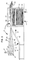
- storage and retrieval device 1 comprises gripper conveyor 2, shingle diverter 3, transfer sheet storage and stager 4, stack formation section 5, and pallet storage 6.
- the next handling step is illustrated as inserter 7, but this device forms no part of the present invention. It can be replaced by any desired handling step or device.
- Gripper conveyor 2 is provided with releases 10, one of which is over each lay down belt 8. Releases 10 open the appropriate grippers (not shown) and deposit the copies onto the respective lay down belts 8.
- the folded edges of the copies are transverse to the direction of movement of belts 8. Since air is often contained in the copies, it is preferably removed by passing them through fold presser 11, which comprises pairs 12 of rollers, there being one pair for each belt 8.
- the present invention is fully operable if the newspaper copies are fed to the shingle diverter and/or stager with their folded edges transverse to the direction of movement of the belts carrying them.
- the folded edges are the longer dimension, the rows of copies will end up being spaced further apart than a standard pallet width. Therefore, it is particularly advantageous for lay down belts 8 to deposit the copies on diverter belts 9, which are at right angles thereto. As a result, the copies are thus positioned with their folded edges parallel to the direction of movement of diverter belts 9 and staging belts 14.
- a further advantage resides in the fact that lay down belts 8 and diverter belts 9 can be separately controlled so that their respective speeds are independent of each other. By suitable adjustment of the relative speeds, the degree of imbrication of the copies can be controlled. Thus, if diverter belts 9 are speeded up relative to feed belts 8, the amount of imbrication will decrease. On the other hand, if diverter belts 9 are slowed relative to feed belts 8, the degree of imbrication will be increased and the leading edges of adjacent copies will be located closer to one another. Since it is desired to maintain an approximately equal thickness of the layers, suitably about 63mm (about 2 1 ⁇ 2 inches), thicker copies require less imbrication than thinner copies. The foregoing mechanism provides a means for making any necessary or desirable adjustments with respect thereto.
- Copies 18 then proceed in the direction of arrows 13 (see Figure 3) and are deposited on adjustable portions 49 of staging belts 14 by diverter belts 9. The copies are then carried to horizontal portions 48 of belts 14 which are located in frame 44.
- Stack 16 of the transfer sheets is beneath staging belts 14. Top sheet 15 is moved in the direction of arrow 45 and, at the same time, staging belts 14 deposit copies 18 thereon, thus forming an imbricated layer.
- stack 16 is moved in the direction of arrows 17 by approximately the thickness of one sheet 15 so as to maintain the top sheet in the same position relative to staging belts 14.
- the staging belts and associated elements of the invention are shown in greater detail in Figure 4.
- belts 14 move in the direction of arrow 21.
- transfer sheet 15 is withdrawn from stack 16 (to the right as shown in Figure 4)
- belts 14 synchronously feed copies 18 thereon, thus forming layers 19 and placing them on top of one another to form layered stack 25.
- Pallet 20 is located at the bottom of stack 25 and is moved in the direction of arrow 23 as layers 19 are deposited at the top thereof.
- the movement of pallet 20 is controlled so that the uppermost layer 19 is always at the proper level to receive sheet 15 and copies 18.
- stack 16 is moved in the direction of arrow 22 as each transfer sheet 15 is removed therefrom, thus keeping the top sheet at the appropriate level.
- Copies 18 are deposited in a predetermined length on one of the three lay down belts 8. When that one is full, it begins transfer to one of diverter belts 9. This is repeated for second and third feed belts 8 and second and third diverter belts 9. In similar manner, diverter belts 9 transfer copies 18 to staging belts 14. Hence, while staging belts 14 are waiting until all three are filled, there is at least one lay down belt 8 and diverter belt 9 which can receive copies 18 from the continuous stream. Thus, there need be no interruption or spaces between the predetermined copy lengths and the device can receive copies 18 from the continuous stream and form them into desired stacks 25.
- FIGs 5 and 6 the operation of stager 4, stack formation section 5, and pallet storage 6 is shown.
- Guides 50 receive sliders 33 which are adapted for motion to the left and right as shown in Figure 6.
- Shovels 34 are mounted on sliders 33 and are movable toward and away from each other in a direction perpendicular to that of sliders 33. Sliders 33 are shown in their extreme left position in the upper portion of Figure 6 and in their extreme right position in the lower portion of that Figure. However, the pairs of sliders 33, and their attached shovels 34, are intended to move in the same direction and at the same time.
- both sliders 33 move to the left position, as shown in the upper part of Figure 6.
- Shovels 34 then move toward each other so as to slide partially under and hold the top most transfer sheet. This position is shown in the upper portion of Figure 6 at stager 4.
- Sliders 33 then move to the right in synchronism with horizontal portion 48 of staging belts 14 (not shown in Figure 6). This position is shown at the lower half of Figure 6 at stack formation section 5.
- the cycle is repeated as needed until the stack is fully formed.
- the leveler (not shown) lowers stack 25 (see Figure 5) so that the uppermost layer is beneath the level of shovels 34 and buffer 27.
- Stack 25 is then removed from the device in a direction transverse to arrows 13 and 29.
- sliders 33 are in their right position as shown in the bottom half of Figure 6.
- Shovels 34 move toward each other and grip pallet 20 at the top of pallet stack 24.
- Sliders 33 then move to their left position, carrying pallet 20 to buffer 27 in stack formation section 5.
- the transfer sheets, with copies 18 synchronously deposited thereon, are moved by sliders 33 and shovels 34 onto buffer 27. Meanwhile, the leveler rises so that it contacts the underside of bottom pallet 20. Thereafter, buffer 27 releases and the stack formation continues until completed.
- stack 25 When stack 25 is completed and removed from the device, it can be stored at any desired or convenient location. Since the system is quite mobile, the stacks can even be stored in a building apart from the one in which the device of the present invention is located.
- stack 25 When it becomes necessary to retrieve copies 18, stack 25 is returned to area 5. In order to maintain the proper orientation of copies 18, it is necessary to rotate stack 25 180° about its vertical axis. It is then returned to area 5 for retrieval.
- Staging belts 14 are reversed and transfer sheet 15 forming part of upper layer 19 is moved in the direction of arrow 37.
- Noses 46 on one end of diverter belts 14 enter between copies 18 and transfer sheets 15.
- Copies 18 are carried onto horizontal portions 48 of staging belts 14, and transfer sheet 15 is placed on the top of stack 16.
- the support for stack 16 then moves in the direction of arrow 39 to prepare stack 16 to receive the next transfer sheet 15.
- the support for pallet 20 moves in the direction of arrow 38.
- the transfer takes place at the same level at all times.
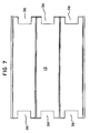
- transfer sheet 15 is provided with notches 36 at one or both ends thereof (see Figure 7). Notches 36 correspond and are complementary to noses 46. This assists in the separation of copies 18 from transfer sheet 15.
- staging belts 14 move in the direction of arrow 47 and feed copies 18 onto diverter belts 9.
- diverter belts 9 move in the direction of arrow 43 to assume retrieval position 42 as shown in phantom. They are then deposited, one row at a time, onto converter table 40, thereby to form single stream 41 which, in the embodiment shown, passes on to inserter 7.
- FIG. 10 A preferred form of the device is shown diagrammatically in Figure 10. This is a view substantially comparable to that of Figure 5.
- Pallet building section 52 contains pallet 20 and stack 25. However, stager 4 and pallet storage 6 are combined into pallet feed section 53.
- Section 53 contains upper pallet 56 and lower pallet 57, carrying stacks 54 and 55 of a predetermined number of transfer sheets, respectively. Operation is initiated by inserting pallet 20, carrying a transfer sheet is placed in section 52. It is elevated in the same manner as in the principal form of the device. As new transfer sheets are needed, they are taken from stack 54; this process continues until stack 54 has one transfer sheet left and stack 25 is complete.
- Stack 25 is then moved out of section 52, preferably in a direction transverse to the direction of flow of the units.
- upper pallet 56 carrying a transfer sheet
- lower pallet 57 carrying stack 55 of transfer sheets
- a new pallet (not shown), also carrying the predetermined number of transfer sheets, is moved into position beneath pallet 55. The cycle is now complete and can be repeated as desired.
- a copy counter (not shown) which senses the presence or absence of copy 18 in each gripper of conveyor 2.
- a gripper counter which counts the grippers of conveyor 2. In this way, it is possible to determine when and where there are "holes" in the copy stream.
- Belts 8 and 9 are controlled so that, when there is a hole, the belt stops for a suitable length of time to allow the next copy 18 to be properly deposited.
Landscapes
- Engineering & Computer Science (AREA)
- Mechanical Engineering (AREA)
- Pile Receivers (AREA)
- Vending Machines For Individual Products (AREA)
- Control And Other Processes For Unpacking Of Materials (AREA)
- Automatic Analysis And Handling Materials Therefor (AREA)
- Container Filling Or Packaging Operations (AREA)
Claims (34)
- Vorrichtung zum Stapeln und/oder Abstapeln eines Flusses von sich überlappenden, im wesentlichen ebenen Stücken (18) zur Bildung und/oder Abstapelung eines geschichteten Stapels (25), wobei die Vorrichtung eine Stapelvorrichtung umfaßt, die angepaßt ist, um einen Fluß der Stücke von einer entsprechenden Quelle entgegenzunehmen, und eine Vielzahl von Übertragungsplatten (15) in einem Plattenstapel (16), wobei zumindest ein Teil des Flusses zu der genannten Stapelvorrichtung geliefert wird; und
die genannte Stapelvorrichtung mindestens einen Stufenriemen (14) aufweist, der angepaßt ist, um den genannten Teilfluß von Stücken aufzunehmen und die Stücke seriell auf einer der Übertragungsplatten (15) in einer Übertragungsrichtung (13) im Gleichlauf mit der Bewegung der einen Übertragungsplatte (15) abzulegen, die von dem genannten Plattenstapel (16) gezogen wird, um eine überlappende Lage zu bilden, die den Teilfluß und die eine Übertragungsplatte umfaßt, wobei die genannte Stapelvorrichtung weiter angepaßt ist, um die genannte überlappende Lage auf einer herausnehmbaren Stützvorrichtung (20) abzulegen und jede aufeinanderfolgende überlappende Lage auf einer unmittelbar vorhergehenden, überlappenden Lage abzulegen, wodurch ein Bündel (25) gebildet wird. - Vorrichtung nach Anspruch 1, worin der Fluß von Stücken von einer Zuführvorrichtung (2, 8) geliefert wird, die einen Vorschubriemen (8) aufweist, auf dem die Stücke (18) liegen, wobel der genannte Vorschubriemen über einem Umleitriemen (9) endet, und der genannte Umleitriemen sich mit einer anderen Geschwindigkeit als der genannte Vorschubriemen bewegen kann, wodurch die Überlappung der Stücke in dem genannten Fluß gesteuert werden kann.
- Vorrichtung nach Anspruch 2, worin der Umleitriemen (9) und der Vorschubriemen (8) in einem rechten Winkel zu einander angeordnet sind.
- Vorrichtung nach einem der Ansprüche 1-3, die überdies eine Falz-Preßvorrichtung (11) umfaßt, die eine Druckkraft auf die Stücke (18) ausübt.
- Vorrichtung nach einem der Ansprüche 1-4, worin die genannte Zuführvorrichtung eine Greif-Fördervorrichtung (2) umfaßt, die angepaßt ist, um die Stücke auf einem Vorschubriemen (8) abzulegen, der genannte Vorschubriemen endet über einem Umleitriemen (9).
- Vorrichtung nach einem der Ansprüche 1-5, worin drei der genannten Teile und drei der genannten Stufenriemen (14) perallel zu und im Abstand von einander angeordnet sind.
- Vorrichtung nach einem der Ansprüche 1-6, worin die genannte Stapelvorrichtung einen Sockel aufweist, der für vertikale Bewegungen angepaßt ist, wobei, wenn die genannte Stapelvorrichtung die genannten überlappenden Lagen (15, 18) ablegt, der Sockel seine vertikale Stellung anpaßt, um die überlappenden Lagen seriell auf einer herausnehmbaren Stützvorrichtung (20) entgegenzunehmen.
- Vorrichtung nach Anspruch 7 mit mehreren der genannten herausnehmbaren Stützvorrichtungen (20) in einem Stützvorrichtungs-Stapel (24), und einem Stützvorrichtungs-Vorschub (33, 34), der angepaßt ist, um eine der genannten herausnehmbaren Stützvorrichtungen (20) zu der genannten Stapelvorrichtung zu bringen, wenn ein vorhergehender genannter geschichteter Stapel fertiggestellt ist.
- Vorrichtung nach Anspruch 8 mit einem Puffer (27), der eine temporäre Stützvorrichtung für eine genannte herausnehmbare Stützvorrichtung (20) zur Verfügung stellt (27), wobei die temporäre Stützvorrichtung angepaßt ist, um die eine herausnehmbare Stützvorrichtung entgegenzunehmen und zu halten, während der vorhergehende geschichtete Stapel (25) und dessen Stützvorrichtung aus der Vorrichtung herausgenommen werden und danach die temporäre Stützvorrichtung auf den Sockel gelassen wird.
- Vorrichtung nach einem der Ansprüche 1-9, worin der genannte Vorschubriemen und die genannte Stapelvorrichtung umkehrbar sind, und ein geneigter Vorsprung (46) angrenzend zu dem genannten Stufenriemen (14) angebracht ist, der angepaßt ist, um zwischen jeder genannten Übertragungsplatte (15) und jedem genannten Teil (18) hineinzupassen, wobei, wenn jede genannte Übertragungsplatte (15) von dem genannten geschichteten Stapel (25) gezogen ist, jedes genannte Teil (18) von dem genannten Stufenriemen (14) entgegengenommen ist.
- Vorrichtung nach Anspruch 10, worin die genannte Zuführvorrichtung einen Umleitriemen (9) umfaßt, der umkehrbar und angepaßt ist, um den genannten Teil (18) von dem Stufenriemen (14) entgegenzunehmen und individuell den genannten jeweiligen Teil auf einem Konvertertisch (40) abzulegen, wodurch ein Ausgangsfluß von sich überlappenden Stücken geschaffen wird.
- Vorrichtung nach Anspruch 10 oder 11, worin jede genannte Übertragungsplatte (15) mehrere Aussparungen (36) entsprechend und komplementär zu den genannten Vorsprüngen (46) hat.
- Vorrichtung nach einem der Ansprüche 1-12, worin der genannte Fluß im wesentlichen kontinuierlich ist.
- Vorrichtung nach einem der Ansprüche 1-4, worin die genannte Zuführvorrichtung eine Greif-Fördervorrichtung (2) ist, und einen ersten Sensor umfaßt, um festzustellen, ob die Stücke in deren Greifer sind, einen zweiten Sensor, um die genannten Greifer zu zählen, und eine Steuervorrichtung zur Steuerung der genannten Vorrichtung, um einen kontinuierlichen genannten Fluß aus Stücke basierend auf Informationen, die von dem genannten ersten Sensor und dem genannten zweiten Sensor empfangen werden, zu erhalten.
- Vorrichtung nach einem der Ansprüche 1-7, die eine Führung (50), eine Schiebevorrichtung (33) in der genannten Führung und Schaufeln (34) auf jeder genannten Schiebevorrichtung umfaßt, wobei die genannte Schiebevorrichtung und die genannten Schaufein zur Bewegung parallel zur genannten Übertragungsrichtung (13) zwischen einer ersten Stellung, die an den genannten Plattenstapel (16) angrenzt, und einer zweiten Stellung, die an den genannten geschichteten Stapel (25) angrenzt, angepaßt werden, und die genannten Schaufeln zur Bewegung auf einander zu in eine Greif-Position und weg von einander in eine Freigabe-Position angepaßt werden, worin, wenn die genannte Schiebevorrichtung (33) in der genannten ersten Stellung ist und die genannten Schaufeln (34) in der genannten Greif-Position, die genannten Schaufeln angepaßt sind, um die genannte Übertragungsplatte zu halten (15) und, wenn sich die genannte Schiebevorrichtung in ihre zweite Stellung bewegt, die genannte Übertragungsplatte auf dem genannten geschichteten Stapel abzulegen (25),
und worin, wenn die genannten Schaufeln (34) in genannter Freigabe-Position sind, sie keinen Kontakt zu den genannten Übertragungsplatten (15) haben und die genannte Schiebevorrichtung (33) sich zwischen genannter ersten Stellung und genannter zweiten Stellung ohne Bewegung der genannten Übertragungsplatte bewegen kann. - Vorrichtung nach Anspruch 15, worin die genannten überlappenden Lagen auf einer herausnehmbaren Stützvorrichtung (20) abgelegt werden, und eine Vielzahl der genannten Stützvorrichtungen in einem Stützvorrichtungs-Stapel (24) sind, wobei ein Stützvorrichtungs-Vorschub (33 34, 50), angepaßt ist, um eine der genannten Stützvorrichtungen zu den genannten Stapeln zu bringen, wenn ein vorhergehender geschichteter Stapel (25) fertiggestellt ist,
der genannte Stützvorrichtungs-Vorschub umfaßt die genannte Schiebevorrichtung (33) mit einer dritten Stellung, die an den genannten Stützvorrichtungs-Stapel angrenzt, die genannten Schaufeln (34) werden, wenn sie in der genannten Greif-Position und die genannte Schiebevorrichtung in der genannten dritten Position sind, angepaßt, um die genannte eine Stützvorrichtung (20) zu halten und, wenn sich die genannte Schiebevorrichtung zu der genannten zweiten Stellung bewegt, die genannte Stützvorrichtung auf einem Sockel für den genannten geschichteten Stapel abzulegen,
wobei, die genannten Schaufeln (34) keinen Kontakt zu der genannten Stützvorrichtung (20) haben, wenn sie in der Freigabe-Position sind, und die genannte Schiebevorrichtung (33) sich zwischen der genannten zweiten Stellung und der genannten dritten Stellung ohne Bewegung der genannten Stützvorrichtung (20) bewegen kann. - Vorrichtung nach Anspruch 15 oder 16, worin die genannte Führung (50) ein Paar Schienen umfaßt und es ein Paar Schiebevorrichtungen (33) gibt, eine auf jeder der genannten Schienen.
- Vorrichtung nach einem der Ansprüche 1-7, die überdies einen Stützvorrichtungs-Vorschub-Abschnitt umfaßt, der eine obere Stützvorrichtung (56) enthält, die einen oberen Plattenstapel (54) trägt, der eine vorbestimmte Anzahl der genannten Übertragungsplatten umfaßt, die genannte eine der genannten Platten ist auf einer entsprechenden Höhe, um das Herausziehen davon zu ermöglichen, und eine untere Stützvorrichtung (57), die einen unteren Plattenstapel (55) trägt, der eine vorbestimmte Anzahl der genannten Übertragungsplatten umfaßt,
der genannte Stützvorrichtungs-Vorschub-Abschnitt ist angepaßt, um die genannte, die eine der Übertragungsplatten tragende obere Stützvorrichtung (56) vom genannten Vorschubabschnitt zu der Stapelvorrichtung (52) zu übertragen, wenn das genannte Bündel (25) vollständig ist, und um die untere Stützvorrichtung (57) und den unteren Stapel (55) zu einem Punkt anzuheben, in dem eine oberste Übertragungsplatte des unteren Stapels in der genannten entsprechenden Höhe ist. - Vorrichtung nach Anspruch 18, worin das genannte Bündel (25) aus der genannten Stapelvorrichtung bewegt wird, bevor oder wenn die Übertragung der genannten oberen Stützvorrichtung (56) zu der genannten Stapelvorrichtung (52) vollständig ist.
- Ein verfahren zur Stapelung eines Flusses von sich überlappenden, im wesentlichen ebenen Stücken (18), um einen geschichteten Stapel zu bilden, mit folgenden Schritten:Lieferung von mindestens einem Teil eines Flusses der genannten Stücke angrenzend an einen Übertragerstapel (16) mit Übertragungsplatten (15), der seriellen Ablage der genannten Stücke auf eine oberste Übertragungsplatte in Gleichlauf mit der Bewegung der genannten obersten Übertragungsplatte, die aus einem entsprechenden Vorrat gezogen wird, wodurch eine überlappende Lage gebildet wird, die den genannten Teil (18) und die genannte oberste Übertragungsplatte (15) umfaßt,Ablage einer ersten genannten überlappenden Lage auf einer ersten Stützvorrichtung (20), und Ablage von jeder nachfolgenden überlappenden Lage auf einer unmittelbar vorhergehenden der genannten Lage, um ein Bündel zu bilden (25).
- Verfahren nach Anspruch 20, worin drei der genannten Teile (18) parallel zu von einander beabstandet sind.
- Verfahren nach Anspruch 20 oder 21 mit Positionierung der genannten ersten Stützvorrichtung (20), um die genannte erste überlappende Lage entgegenzunehmen, anschließend Absenkung (23) der genannten ersten Stützvorrichtung um eine erste Höhe, die ungefähr gleich der Höhe der genannten ersten überlappenden Lage ist, Entgegennahme der genannten aufeinanderfolgenden überlappenden Lagen und Absenkung der genannten Stützvorrichtung um die genannte erste Hohe nach Erhalt einer jeden der genannten aufeinanderfolgenden Lagen durch die genannte erste Stützvorrichtung.
- Verfahren nach Anspruch 22 mit einer weiteren Absenkung der genannten Stützvorrichtung nachdem der genannte geschichtete Stapel vollständig ist, Einführung einer zweiten genannten Stützvorrichtung über dem genannten geschichteten Stapel, und Herausziehen des genannten geschichtete Stapel unterhalb der genannten zweiten Stützvorrichtung.
- Verfahren nach Anspruch 20 oder 21, worin der genannte Zyklus nach Vervollständigung des genannten ersten geschichteten Stapels (25) zur Bildung von aufeinanderfolgenden genannten geschichteten Stapeln wiederholt wird.
- Verfahren nach einem der Ansprüche 20-24, das überdies das Herausziehen einer obersten genannten überlappenden Lage aus dem genannten geschichteten Stapel (25) umfaßt, das Sondieren des genannten Teils (18) von der genannten Übertragungsplatte, die Rückgabe der genannten Übertragungsplatte (15) zum genannten Vorrat (16), und die Entladung des genannten Teils.
- Verfahren nach Anspruch 23, worin der genannte geschichtete Stapel herausgezogen wird, während die genannte zweite Stützvorrichtung über dem genannten Stapel eingeführt wird.
- Verfahren nach einem der Ansprüche 20-26, das eine Abtastung umfaßt, um fehlende Stücke in dem genannten Fluß zu erfassen, eine Steuerung der genannten Vorrichtung zum Erhalt eines kontinuierlichen genannten Flusses basierend auf Informationen bezüglich genannter fehlender Stücke.
- Verfahren nach einem der Ansprüche 20-27, worin der genannte Vorrat eine obere Stützvorrichtung umfaßt (56), die einen oberen Plattenstapel trägt (54), der eine vorbestimmte Anzahl der genannten Übertragungsplatten umfaßt, die genannte oberste Übertragungsplatte befindet sich in einer entsprechenden Höhe zur Ermöglichung des Herausziehens, und eine untere Stützvorrichtung (51), die einen unteren Plattenstapel (55) trägt, der eine vorbestimmte Anzahl der genannten Übertragungsplatten umfaßt,
Anhebung der genannten oberen Stützvorrichtung um eine Höhe, die ungefähr gleich der Höhe von der genannten obersten Übertragungsplatte ist, nach dem Herausziehen einer jeden genannten obersten Übertragungsplatte aus dem genannten oberen Stapel,
wenn genanntes Bündel (25) vollständig ist, Übertragung der genannten oberen Stützvorrichtung und eine der genannten Übertragungsplatten zu einer Stellung, um genannten Teil des genannten Flusses entgegenzunehmen, und Anhebung der genannten unteren Stützvorrichtung und des genannten unteren Stapels so, daß eine oberste Platte vom genannten unteren Plattenstapel auf der genannten entsprechenden Höhe ist. - Verfahren nach Anspruch 28, worin eine weitere Stützvorrichtung, die einen weiteren Plattenstapel trägt, der eine vorbestimmte Anzahl von Übertragungsplatten umfaßt, unterhalb der genannten unteren Stützvorrichtung angeordnet ist, wenn oder nachdem die genannte Anhebung stattfindet.
- Verfahren zum Abstapeln eines geschichteten Stapels (25) mit sich überlappenden ebenen Stücken, das folgendes umfaßt:- einen Zyklus des Herausziehens einer überlappenden Lage aus dem genannten geschichteten Stapel (25), die eine Übertragungsplatte (15) umfaßt, die eine Vielzahl der genannten Stücke (18) stützt, und Ablegen der genannten Übertragungsplatte (15), um einen Plattenstapel (16) zu bilden; und- Sammeln der Vielzahl von Stücken auf einem Stufenriemen (14), um die genannten Stücke (18) nacheinander von der genannten Übertragungsplatte (15) abzusondern, synchron mit mindestens einem Teil der Bewegung der genannten Übertragungsplatte (15) von dem genannten geschichteten Stapel (25) zu dem Plattenstapel, um einen Ausgangsfluß aus den Stücken zu bilden.
- Verfahren nach Anspruch 30, worin das genannte Herausziehen, das genannte Absondern, und das genannte Ablegen im wesentlichen simultan verläuft.
- Verfahren nach Anspruch 30 oder 31, worin die genannte überlappende Lage drei Reihen aus den genannten Stücken (18) auf der genannten Übertragungsplatte (15) umfaßt, die genannten Reihen sind parallel zu und im Abstand von einander.
- Verfahren nach einem der Ansprüche 30-32, das das Anheben (36) des genannten geschichteten Stapels (25) nach jedem genannten Herausziehen um eine erste Höhe umfaßt, die ungefähr gleich der Hohe der genannten überlappenden Lage ist, das Herausziehen von aufeinanderfolgenden überlappenden Lagen und Anheben des genannten geschichteten Stapels in der genannten ersten Höhe nach dem Herausziehen von jeder der genannten aufeinanderfolgenden Lagen.
- Verfahren nach einem der Ansprüche 30-33, worin der genannte Zyklus wiederholt wird, bis alle genannten überlappenden Lagen aus dem genannten geschichteten Stapel herausgezogen worden sind.
Applications Claiming Priority (4)
| Application Number | Priority Date | Filing Date | Title |
|---|---|---|---|
| US85041492A | 1992-03-12 | 1992-03-12 | |
| US850414 | 1992-03-12 | ||
| US980768 | 1992-11-24 | ||
| US07/980,768 US5336041A (en) | 1992-03-12 | 1992-11-24 | Storage and retrieval device and method for imbricated planar articles |
Publications (2)
| Publication Number | Publication Date |
|---|---|
| EP0560680A1 EP0560680A1 (de) | 1993-09-15 |
| EP0560680B1 true EP0560680B1 (de) | 1997-08-13 |
Family
ID=27126930
Family Applications (1)
| Application Number | Title | Priority Date | Filing Date |
|---|---|---|---|
| EP93400617A Expired - Lifetime EP0560680B1 (de) | 1992-03-12 | 1993-03-11 | Lager- und Ausgabevorrichtung und Verfahren für in einem Schuppenstrom anfallende Produkte |
Country Status (5)
| Country | Link |
|---|---|
| US (1) | US5336041A (de) |
| EP (1) | EP0560680B1 (de) |
| AT (1) | ATE156776T1 (de) |
| DE (1) | DE69312988T2 (de) |
| DK (1) | DK0560680T3 (de) |
Families Citing this family (11)
| Publication number | Priority date | Publication date | Assignee | Title |
|---|---|---|---|---|
| CH685992A5 (de) * | 1992-07-22 | 1995-11-30 | Grapha Holding Ag | Einrichtung fur die Verarbeitung von Druckprodukten. |
| ES2112574T3 (es) * | 1994-05-02 | 1998-04-01 | Ferag Ag | Procedimiento y dispositivo para almacenar preformas. |
| US5788461A (en) * | 1996-02-02 | 1998-08-04 | Alvey, Inc. | Automatic depalletizer |
| US5899659A (en) * | 1996-02-02 | 1999-05-04 | Alvey, Inc. | Depalletizer collector belt assembly |
| NO20003443L (no) * | 2000-07-03 | 2002-01-04 | Mach Design Group As | Fremgangsmåte og anordning til plassering av stötteark under lag av gjenstander i en stabel |
| US6899512B2 (en) | 2000-08-07 | 2005-05-31 | J & L Development, Inc. | Bottom sheet inserter |
| US20020124704A1 (en) * | 2000-08-07 | 2002-09-12 | Roth Curtis A. | Roll feed bottom sheet inserter |
| CN102369151A (zh) * | 2009-02-20 | 2012-03-07 | Amb阿帕帕蒂+机械有限公司 | 用于分离板型元件的设备 |
| US10011444B2 (en) | 2012-11-02 | 2018-07-03 | Packaging Progressions, Inc. | Bacon card feeding system |
| US9309059B2 (en) * | 2012-11-02 | 2016-04-12 | Packaging Progressions, Inc. | Bacon card feeding system |
| US10179886B2 (en) | 2016-05-17 | 2019-01-15 | Afton Chemical Corporation | Synergistic dispersants |
Family Cites Families (9)
| Publication number | Priority date | Publication date | Assignee | Title |
|---|---|---|---|---|
| US3840130A (en) * | 1972-11-01 | 1974-10-08 | Harris Intertype Corp | Method and apparatus for storing sheet material articles |
| CH570920A5 (de) * | 1974-05-28 | 1975-12-31 | Ferag Ag | |
| CH654554A5 (de) * | 1981-12-09 | 1986-02-28 | Ferag Ag | Verfahren und vorrichtung zur entnahme von auf einen wickelkern aufgewickelten flaechigen erzeugnissen, vorzugsweise druckprodukten. |
| CH680509A5 (de) * | 1986-11-21 | 1992-09-15 | Ferag Ag | |
| DE3860529D1 (de) * | 1988-01-13 | 1990-10-04 | Ferag Ag | Verfahren und vorrichtung zum veraendern des ueberlappungsgrades von in einem schuppenstrom gefoerderten druckereiprodukten. |
| US4927318A (en) * | 1988-02-09 | 1990-05-22 | Galpin Research, Limited Partnership | Method for forming, grasping and handling cubes of stacked printed products |
| US4987809A (en) * | 1989-03-24 | 1991-01-29 | The Wessel Company, Inc. | Production of small-sized printed products |
| DE3940190A1 (de) * | 1989-12-05 | 1991-06-06 | Kolbus Gmbh & Co Kg | Verfahren zum be- und entladen von paletten mit stapeln von flaechigen produkten und einrichtung zur durchfuehrung des verfahrens |
| US5311995A (en) * | 1991-07-02 | 1994-05-17 | Graphic Management Associates, Inc. | Stack for storing imbricated sheets |
-
1992
- 1992-11-24 US US07/980,768 patent/US5336041A/en not_active Expired - Fee Related
-
1993
- 1993-03-11 AT AT93400617T patent/ATE156776T1/de not_active IP Right Cessation
- 1993-03-11 EP EP93400617A patent/EP0560680B1/de not_active Expired - Lifetime
- 1993-03-11 DK DK93400617.2T patent/DK0560680T3/da active
- 1993-03-11 DE DE69312988T patent/DE69312988T2/de not_active Expired - Fee Related
Also Published As
| Publication number | Publication date |
|---|---|
| EP0560680A1 (de) | 1993-09-15 |
| ATE156776T1 (de) | 1997-08-15 |
| DE69312988T2 (de) | 1998-03-26 |
| US5336041A (en) | 1994-08-09 |
| DK0560680T3 (da) | 1998-03-16 |
| DE69312988D1 (de) | 1997-09-18 |
Similar Documents
| Publication | Publication Date | Title |
|---|---|---|
| US5375967A (en) | Method and apparatus for palletizing and depalletizing | |
| FI111069B (fi) | Laite pinojen muodostamiseksi taitetuista painotuotteista | |
| EP0560680B1 (de) | Lager- und Ausgabevorrichtung und Verfahren für in einem Schuppenstrom anfallende Produkte | |
| EP1055621A2 (de) | Automatisches Tafelzuführungssystem | |
| JPS6351223A (ja) | 包装機械に用紙を送る搬送装置 | |
| EP0399623A2 (de) | Vorrichtung zum Stapeln von Wellpappenabschnitten | |
| JPS6210897B2 (de) | ||
| US5769413A (en) | Process and apparatus for automatic stack changing | |
| JPS59194935A (ja) | 袋詰充填物のパレット積載方法及び装置 | |
| EP0911287A2 (de) | Beschickungsvorrichtung für ein Entstapelmagazin zum Fördern von vertikalen Signaturen zu einer Bindeeinrichtung | |
| US5190281A (en) | Vertical signature stacking system having a non-contact sensor to control stack formation | |
| US7699578B2 (en) | Method and device for forming bundles of stackable objects | |
| JP2001515002A (ja) | 給送装置 | |
| US6691996B2 (en) | Lap separator for sheet-receiving pockets and method for separating laps in sheet-receiving pockets | |
| JPH0812160A (ja) | シート状製品を排出位置へ連続的に送る装置 | |
| US6695302B1 (en) | Method and apparatus for separating a stream of spaced documents into discrete groups | |
| US6220590B1 (en) | Hopper loader with a conveyer having slippage resistance | |
| US6189827B1 (en) | Process and apparatus for storing blanks | |
| US5511935A (en) | Paper stack conveyor | |
| JPH0780575B2 (ja) | 印刷機の為の封筒フィーダー | |
| JP4921063B2 (ja) | 印刷枚葉紙を丁合いする方法および装置 | |
| EP0522890B1 (de) | Verfahren und Apparat zum Speichern von Blättern in Schuppenformation auf einer Palette | |
| US20060175745A1 (en) | Buffer and offsetting elevator for sheet handling | |
| US20040245716A1 (en) | Vertical pocket feeder | |
| JP2003285962A (ja) | 紙葉堆積体を形成しかつ移送するための分割ベルトを備えている装置 |
Legal Events
| Date | Code | Title | Description |
|---|---|---|---|
| PUAI | Public reference made under article 153(3) epc to a published international application that has entered the european phase |
Free format text: ORIGINAL CODE: 0009012 |
|
| AK | Designated contracting states |
Kind code of ref document: A1 Designated state(s): AT BE CH DE DK ES FR GB GR IE IT LI NL PT SE |
|
| 17P | Request for examination filed |
Effective date: 19940310 |
|
| 17Q | First examination report despatched |
Effective date: 19960117 |
|
| GRAG | Despatch of communication of intention to grant |
Free format text: ORIGINAL CODE: EPIDOS AGRA |
|
| GRAH | Despatch of communication of intention to grant a patent |
Free format text: ORIGINAL CODE: EPIDOS IGRA |
|
| GRAH | Despatch of communication of intention to grant a patent |
Free format text: ORIGINAL CODE: EPIDOS IGRA |
|
| GRAA | (expected) grant |
Free format text: ORIGINAL CODE: 0009210 |
|
| AK | Designated contracting states |
Kind code of ref document: B1 Designated state(s): AT BE CH DE DK ES FR GB GR IE IT LI NL PT SE |
|
| PG25 | Lapsed in a contracting state [announced via postgrant information from national office to epo] |
Ref country code: NL Free format text: LAPSE BECAUSE OF FAILURE TO SUBMIT A TRANSLATION OF THE DESCRIPTION OR TO PAY THE FEE WITHIN THE PRESCRIBED TIME-LIMIT Effective date: 19970813 Ref country code: IT Free format text: LAPSE BECAUSE OF FAILURE TO SUBMIT A TRANSLATION OF THE DESCRIPTION OR TO PAY THE FEE WITHIN THE PRE;WARNING: LAPSES OF ITALIAN PATENTS WITH EFFECTIVE DATE BEFORE 2007 MAY HAVE OCCURRED AT ANY TIME BEFORE 2007. THE CORRECT EFFECTIVE DATE MAY BE DIFFERENT FROM THE ONE RECORDED.SCRIBED TIME-LIMIT Effective date: 19970813 Ref country code: GR Free format text: LAPSE BECAUSE OF FAILURE TO SUBMIT A TRANSLATION OF THE DESCRIPTION OR TO PAY THE FEE WITHIN THE PRESCRIBED TIME-LIMIT Effective date: 19970813 Ref country code: FR Free format text: LAPSE BECAUSE OF FAILURE TO SUBMIT A TRANSLATION OF THE DESCRIPTION OR TO PAY THE FEE WITHIN THE PRESCRIBED TIME-LIMIT Effective date: 19970813 Ref country code: ES Free format text: THE PATENT HAS BEEN ANNULLED BY A DECISION OF A NATIONAL AUTHORITY Effective date: 19970813 Ref country code: BE Effective date: 19970813 |
|
| REF | Corresponds to: |
Ref document number: 156776 Country of ref document: AT Date of ref document: 19970815 Kind code of ref document: T |
|
| REG | Reference to a national code |
Ref country code: CH Ref legal event code: EP |
|
| REF | Corresponds to: |
Ref document number: 69312988 Country of ref document: DE Date of ref document: 19970918 |
|
| PG25 | Lapsed in a contracting state [announced via postgrant information from national office to epo] |
Ref country code: PT Effective date: 19971114 |
|
| REG | Reference to a national code |
Ref country code: CH Ref legal event code: NV Representative=s name: ABREMA AGENCE BREVETS ET MARQUES GANGUILLET & HUMP |
|
| EN | Fr: translation not filed | ||
| NLV1 | Nl: lapsed or annulled due to failure to fulfill the requirements of art. 29p and 29m of the patents act | ||
| PG25 | Lapsed in a contracting state [announced via postgrant information from national office to epo] |
Ref country code: IE Free format text: LAPSE BECAUSE OF NON-PAYMENT OF DUE FEES Effective date: 19980311 |
|
| REG | Reference to a national code |
Ref country code: DK Ref legal event code: T3 |
|
| PLBE | No opposition filed within time limit |
Free format text: ORIGINAL CODE: 0009261 |
|
| STAA | Information on the status of an ep patent application or granted ep patent |
Free format text: STATUS: NO OPPOSITION FILED WITHIN TIME LIMIT |
|
| 26N | No opposition filed | ||
| REG | Reference to a national code |
Ref country code: GB Ref legal event code: IF02 |
|
| PGFP | Annual fee paid to national office [announced via postgrant information from national office to epo] |
Ref country code: DK Payment date: 20040123 Year of fee payment: 12 |
|
| PGFP | Annual fee paid to national office [announced via postgrant information from national office to epo] |
Ref country code: SE Payment date: 20040304 Year of fee payment: 12 |
|
| PGFP | Annual fee paid to national office [announced via postgrant information from national office to epo] |
Ref country code: GB Payment date: 20040310 Year of fee payment: 12 |
|
| PGFP | Annual fee paid to national office [announced via postgrant information from national office to epo] |
Ref country code: AT Payment date: 20040311 Year of fee payment: 12 |
|
| PGFP | Annual fee paid to national office [announced via postgrant information from national office to epo] |
Ref country code: CH Payment date: 20040317 Year of fee payment: 12 |
|
| PGFP | Annual fee paid to national office [announced via postgrant information from national office to epo] |
Ref country code: DE Payment date: 20040318 Year of fee payment: 12 |
|
| PG25 | Lapsed in a contracting state [announced via postgrant information from national office to epo] |
Ref country code: GB Free format text: LAPSE BECAUSE OF NON-PAYMENT OF DUE FEES Effective date: 20050311 Ref country code: AT Free format text: LAPSE BECAUSE OF NON-PAYMENT OF DUE FEES Effective date: 20050311 |
|
| PG25 | Lapsed in a contracting state [announced via postgrant information from national office to epo] |
Ref country code: SE Free format text: LAPSE BECAUSE OF NON-PAYMENT OF DUE FEES Effective date: 20050312 |
|
| PG25 | Lapsed in a contracting state [announced via postgrant information from national office to epo] |
Ref country code: LI Free format text: LAPSE BECAUSE OF NON-PAYMENT OF DUE FEES Effective date: 20050331 Ref country code: DK Free format text: LAPSE BECAUSE OF NON-PAYMENT OF DUE FEES Effective date: 20050331 Ref country code: CH Free format text: LAPSE BECAUSE OF NON-PAYMENT OF DUE FEES Effective date: 20050331 |
|
| PG25 | Lapsed in a contracting state [announced via postgrant information from national office to epo] |
Ref country code: DE Free format text: LAPSE BECAUSE OF NON-PAYMENT OF DUE FEES Effective date: 20051001 |
|
| EUG | Se: european patent has lapsed | ||
| REG | Reference to a national code |
Ref country code: CH Ref legal event code: PL |
|
| GBPC | Gb: european patent ceased through non-payment of renewal fee |
Effective date: 20050311 |
|
| REG | Reference to a national code |
Ref country code: DK Ref legal event code: EBP |