US5757543A - Keplerian variable magnification finder - Google Patents
Keplerian variable magnification finder Download PDFInfo
- Publication number
- US5757543A US5757543A US08/607,644 US60764496A US5757543A US 5757543 A US5757543 A US 5757543A US 60764496 A US60764496 A US 60764496A US 5757543 A US5757543 A US 5757543A
- Authority
- US
- United States
- Prior art keywords
- lens unit
- sub
- refracting power
- objective system
- lens
- Prior art date
- Legal status (The legal status is an assumption and is not a legal conclusion. Google has not performed a legal analysis and makes no representation as to the accuracy of the status listed.)
- Expired - Fee Related
Links
Images


Classifications
-
- G—PHYSICS
- G02—OPTICS
- G02B—OPTICAL ELEMENTS, SYSTEMS OR APPARATUS
- G02B23/00—Telescopes, e.g. binoculars; Periscopes; Instruments for viewing the inside of hollow bodies; Viewfinders; Optical aiming or sighting devices
- G02B23/14—Viewfinders
-
- G—PHYSICS
- G02—OPTICS
- G02B—OPTICAL ELEMENTS, SYSTEMS OR APPARATUS
- G02B15/00—Optical objectives with means for varying the magnification
- G02B15/14—Optical objectives with means for varying the magnification by axial movement of one or more lenses or groups of lenses relative to the image plane for continuously varying the equivalent focal length of the objective
- G02B15/143—Optical objectives with means for varying the magnification by axial movement of one or more lenses or groups of lenses relative to the image plane for continuously varying the equivalent focal length of the objective having three groups only
- G02B15/1435—Optical objectives with means for varying the magnification by axial movement of one or more lenses or groups of lenses relative to the image plane for continuously varying the equivalent focal length of the objective having three groups only the first group being negative
- G02B15/143507—Optical objectives with means for varying the magnification by axial movement of one or more lenses or groups of lenses relative to the image plane for continuously varying the equivalent focal length of the objective having three groups only the first group being negative arranged -++
-
- G—PHYSICS
- G02—OPTICS
- G02B—OPTICAL ELEMENTS, SYSTEMS OR APPARATUS
- G02B23/00—Telescopes, e.g. binoculars; Periscopes; Instruments for viewing the inside of hollow bodies; Viewfinders; Optical aiming or sighting devices
- G02B23/14—Viewfinders
- G02B23/145—Zoom viewfinders
Definitions
- This invention relates to a finder suitable for use in a lens shutter camera and the like in which a photographic lens system is provided which is independent of a finder lens system.
- Keplerian finders are designed so that a field frame and additional marks are provided adjacent to the intermediate image plane of an objective system and can be observed through an ocular system. Thus, the boundary line of the frame is sharply viewed. Moreover, since a visual field itself can be clearly recognized with little flare, the view of the visual field is very fine.
- An entrance window because its location is near an entrance pupil, can be designed to diminish in size, and compactness of the finder can be achieved, depending upon how each of prisms constituting an image erecting system is configured to bend an optical path. For these reasons, the Keplerian finders have been often used as finders for high-grade lens shutter cameras in particular. However, a drawback is that dust particles that adhere to the periphery of the intermediate image plane usually can be seen, great care must be exercised at the manufacturing stage of the finder to avoid this difficulty.
- Such a Keplerian finder compared with a conventional Albada finder, has the great advantage that the view of the visual field is favorable. On the other hand, it has the defect in that since the entire system of the finder includes an objective system, an image erecting system, and an ocular system, the overall length of the finder is greater when such a finder is mounted in a camera, the thickness of a camera body becomes greater. With a variable magnification finder in particular, a space sufficient for moving lenses is required to vary the magnification of the finder and the entire length of the objective system becomes larger. This is responsible for a further increase in the thickness of the camera body.
- the position and size of an exit pupil also become important.
- the size of the exit pupil namely the so-called pupil diameter
- the pupil diameter is closely connected with likelihood of vignetting the visual field which is caused when the photographer's eye is moved up and down or from side to side. If the pupil diameter is relatively small, the positional relationship between the photographer and the camera body will be seriously prejudiced, thus making it very difficult to see through the finder. Consequently, the enlargement of the pupil diameter is also an important matter.
- Keplerian finders many objective systems which are constructed as zoom lens systems have been invented in the past, and zoom lens systems for varying the magnification of the finder are available in various types.
- an objective system composed of three lens units having negative, positive, and positive powers, respectively, is favorably corrected for aberrations and can be compactly designed.
- Keplerian variable magnification finders having the objective systems mentioned above are known which are disclosed, for example, in Japanese Patent Preliminary Publication Nos. Hei 1-131510, Hei 4-53914, Hei 4-219711, and Hei 6-51201. Any of these finders is such that the objective system is constructed with three zoom lens units with negative, positive, and positive powers so that a first lens unit is fixed and second and third lens units are moved to change the magnification and compensate for the positional shift of an image plane.
- the finder disclosed in Hei 1-131510 mentioned above is constructed so that when the magnification is changed from a low magnification position to a high magnification position, the second lens unit of the objective system is moved toward an object and the third lens unit is moved toward an image.
- the second lens unit practically bears variable magnification behavior and the third lens unit mainly serves to compensate for the positional shift of the image plane.
- the prior art finders disclosed after this are such that as the result that the back focal distance of the objective system is increased so that reflecting surfaces for forming an erect image can be placed in the objective system, the third lens unit gradually comes to bear the variable magnification behavior and can be moved together with the second lens unit toward the object.
- the third lens unit completely bears the variable magnification behavior.
- a finder with the pupil of enlarged diameter is disclosed, for example, in Japanese Patent Preliminary Publication No. Hei 4-214517.
- This finder is such that the objective system is constructed with two zoom lens units having negative and positive powers, a first lens unit composed of two lenses and a second lens unit composed of three lenses, and the pupil diameter is 5 mm in the whole variable magnification range from the low magnification position to the high magnification position.
- any of the finders set forth in Hei 1-131510, Hei 4-53914, Hei 4-219711, and Hei 6-51201 although low in the variable magnification ratio, has a relatively long entire length and thus is unsuitable for compactness of the camera.
- the pupil diameter is as small as 4 mm, it is hard to see through the finder.
- the finder set forth in Hei 4-214517 is such that the pupil diameter is as large as 5 mm, but lenses constituting the finder are numerous and heavy because they are made of glass. As such, this finder has a disadvantage of being high in cost. Additionally, the finder has a relatively long entire length, and thus is unsuitable for a compact camera.
- Keplerian variable magnification finder which bears a high variable magnification ratio, is relatively small in overall length, and has high performance.
- Another object of the present invention is to provide a Keplerian variable magnification finder which has a relatively large pupil diameter so that a photographer can easily see through the finder.
- the Keplerian variable magnification finder includes, in order from the object side, an objective system having a positive refracting power as a whole, an image erecting system for erecting an intermediate image formed by the objective system, and an eyepiece system having a positive refracting power as a whole.
- the objective system is equipped with, in order from the object side, a first lens unit having a negative refracting power, a second lens unit having a positive refracting power, and a third lens unit having a positive refracting power so that when the magnification of the finder is changed, the second and third lens units can be moved along the optical axis.
- the objective system satisfies the following conditions at the same time:
- f 1 is the focal length of the first lens unit
- f 3 is the focal length of the third lens unit
- the Keplerian variable magnification finder includes, in order from the object side, an objective system having a positive refracting power as a whole, an image erecting system for erecting an intermediate image formed by the objective system, and an eyepiece system having a positive refracting power as a whole.
- the objective system is equipped with, in order from the object side, a first lens unit having a negative refracting power, a second lens unit having a positive refracting power, and a third lens unit having a positive refracting power so that when the magnification of the finder is changed, the second and third lens units can be moved along the optical axis.
- Each lens unit is composed of a single lens and the second or third lens unit is configured as a lens, both surfaces of which are aspherical.
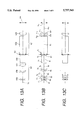
- FIGS. 1A, 1B, and 1C are sectional views showing arrangements, developed along an optical axis, at low, moderate, and high magnification positions, respectively, of the optical system of a first embodiment of the Keplerian variable magnification finder according to the present invention
- FIGS. 2A, 2B, and 2C are diagrams showing characteristics of spherical aberration, astigmatism, and distortion, respectively, at the low magnification position with an infinite object point of the optical system of the first embodiment;
- FIGS. 3A, 3B, and 3C are diagrams showing characteristics of spherical aberration, astigmatism, and distortion, respectively, at the moderate magnification position with the infinite object point of the optical system of the first embodiment;
- FIGS. 4A, 4B, and 4C are diagrams showing characteristics of spherical aberration, astigmatism, and distortion, respectively, at the high magnification position with the infinite object point of the optical system of the first embodiment;
- FIGS. 5A, 5B, and 5C are sectional views showing arrangements, developed along an optical axis, at low, moderate, and high magnification positions, respectively, of the optical system of a second embodiment of the Keplerian variable magnification finder according to the present invention
- FIGS. 6A, 6B, and 6C are diagrams showing characteristics of spherical aberration, astigmatism, and distortion, respectively, at the low magnification position with an infinite object point of the optical system of the second embodiment;
- FIGS. 7A, 7B, and 7C are diagrams showing characteristics of spherical aberration, astigmatism, and distortion, respectively, at the moderate magnification position with the infinite object point of the optical system of the second embodiment;
- FIGS. 8A, 8B, and 8C are diagrams showing characteristics of spherical aberration, astigmatism, and distortion, respectively, at the high magnification position with the infinite object point of the optical system of the second embodiment;
- FIGS. 9A, 9B, and 9C are sectional views showing arrangements, developed along an optical axis, at low, moderate, and high magnification positions, respectively, of the optical system of a third embodiment of the Keplerian variable magnification finder according to the present invention.
- FIGS. 10A, 10B, and 10C are diagrams showing characteristics of spherical aberration, astigmatism, and distortion, respectively, at the low magnification position with an infinite object point of the optical system of the third embodiment;
- FIGS. 11A, 11B, and 11C are diagrams showing characteristics of spherical aberration, astigmatism, and distortion, respectively, at the moderate magnification position with the infinite object point of the optical system of the third embodiment;
- FIGS. 12A, 12B, and 12C are diagrams showing characteristics of spherical aberration, astigmatism, and distortion, respectively, at the high magnification position with the infinite object point of the optical system of the third embodiment;
- FIGS. 13A, 13B, and 13C are sectional views showing arrangements, developed along an optical axis, at low, moderate, and high magnification positions, respectively, of the optical system of a fourth embodiment of the Keplerian variable magnification finder according to the present invention.
- FIGS. 14A, 14B, and 14C are diagrams showing characteristics of spherical aberration, astigmatism, and distortion, respectively, at the low magnification position with an infinite object point of the optical system of the fourth embodiment;
- FIGS. 15A, 15B, and 15C are diagrams showing characteristics of spherical aberration, astigmatism, and distortion, respectively, at the moderate magnification position with the infinite object point of the optical system of the fourth embodiment.
- FIGS. 16A, 16B, and 16C are diagrams showing characteristics of spherical aberration, astigmatism, and distortion, respectively, at the high magnification position with the infinite object point of the optical system of the fourth embodiment.
- the image erecting system is configured to bend the optical path, and thus its thickness can be made small, to some extent, depending upon how the path is bent.
- objective system on the other hand, it is difficult to do so because when the magnification of the finder is changed, individual lens units constituting the objective system must be moved along the optical axis.
- the entire length of the objective system forms a chief factor in the determination of thickness of the camera.
- Factors affecting the entire length of the objective system include (1) thicknesses of lenses of individual lens units constituting the objective system, (2) space required for moving the individual lens units, and (3) the back focal distance of the objective system.
- the above-mentioned arrangement is adopted to thereby limit the space required for moving individual lens units of the objective system when the magnification is changed, so that the design of the finder for a camera of small thickness is achieved.
- the back focal distance of the objective system is increased to some extent, and some of reflecting surfaces for erecting an image are placed in this space. In this way, by replacing the back focal distance of the objective system by the length of the image erecting system, the length of the finder can be diminished accordingly.
- Eq. (1) previously described is provided for the purpose of properly holding the back focal distance. If the value of
- the third lens unit of the objective system practically bears variable magnification behavior, and hence, in order to narrow the space required for moving individual lens units when the magnification is varied, it is required that the amount of movement of the third lens unit is decreased.
- a condition required for this is given by Eq. (2). If the value of f 3 /(f S Z) exceeds the upper limit of Eq. (2), the power of the third lens unit will be lessened and the amount of movement of the third lens unit for varying the magnification will be increased. If, on the other hand, the value of f 3 /(f S Z) is less than the lower limit of Eq. (2), the power of the third lens unit will be strengthened and the amount of movement of the third lens unit will be decreased, but correction for aberration becomes difficult. For this reason, it is necessary that additional lenses are placed in the objective system to correct for aberration. This situation is not favorable.
- each lens unit included in the objective system is composed of a single lens so that the entire length of the finder is prevented from increasing.
- Eqs. (1) and (2) are satisfied, the increase of the entire length of the finder can be kept to a minimum even though additional lenses are placed in order that aberration is more favorably corrected.
- the finder of the present invention is such that an axial ray of light, after being made divergent by a strong negative power that the first lens unit possesses, is incident on the second and third lens units each having a positive power and is introduced through the image erecting system and the eyepiece system into a photographer's eye. Therefore, the axial ray has a maximum ray height in the second or third lens unit, where spherical aberration of undercorrection is produced.
- spherical aberration has been corrected by a negative power the first lens unit possesses or by providing at least one surface of each lens unit with an aspherical surface.
- the finder of the present invention uses a lens whose surfaces are both configured to be aspherical in the second or third lens unit in which the axial ray has the maximum ray height.
- the second or third lens unit is composed of a single lens, both surfaces of which are configured to be aspherical. It is desirable that this lens has such a shape that the power of the positive lens is weakened progressively in separating from the optical axis.
- the finder of this embodiment includes, in order from the object side, an objective system 11 composed of a first lens unit 11a with a negative refracting power, a second lens unit 11b with a positive refracting power, and a third lens unit 11c with a positive refracting power; and an eyepiece system 12 composed of a prism 12a as a reflecting member and an eyepiece 12b.
- a stop 13 is placed between the objective system 11 and the eyepiece system 12.
- An intermediate image plane produced by the objective system 11 is formed at the foremost surface of the prism 12a.
- the first lens unit 11a is fixed and the second and third lens units 11b and 11c are moved along an optical axis Lc to vary the magnification of the finder. Further, a first reflecting surface 14a and a second reflecting surface 14b are arranged between the objective system 11 and the stop 13.
- the prism 12a has two reflecting surfaces. The first and second reflecting surfaces 14a and 14b and the prism 12a constitute an image erecting system.
- the first, second, and third lens units 11a, 11b, and 11c and the eyepiece 12b are each constructed with a single lens.
- Reference numeral 15 represents an eyepoint.
- each of the first and second reflecting surfaces 14a and 14b is composed of a roof mirror, and the prism 12a is constructed with a pentagonal prism.
- optical members such as lenses
- Keplerian variable magnification finder The numerical data of optical members, such as lenses, constituting the Keplerian variable magnification finder according to the first embodiment is shown below.
- Eqs. (1) and (2) in the Keplerian variable magnification finder of the first embodiment are as follows:
- FIGS. 2A-2C, 3A-3C, and 4A-4C are aberration curve diagrams of the optical system in the first embodiment.
- the finder of this embodiment includes, in order from the object side, an objective system 21 composed of a first lens unit 21a with a negative refracting power, a second lens unit 21b with a positive refracting power, a third lens unit 21c with a positive refracting power, and a prism 21d as a reflecting member; and an eyepiece system 22 composed of a prism 22a as a reflecting member and an eyepiece 22b.
- a stop 23 is placed between the objective system 21 and the eyepiece system 22.
- An intermediate image plane produced by the objective system 21 is formed at the foremost surface of the prism 22a.
- the first lens unit 21a is fixed and the second and third lens units 21b and 21c are moved along the optical axis Lc so that the magnification of the finder is changed.
- the prisms 21d and 22a each have two reflecting surfaces and constitute an image erecting system.
- the first, second, and third lens units 21a, 21b, and 21c and the eyepiece 22b are each constructed with a single lens.
- Reference numeral 24 represents an eyepoint.
- the prism 21d is composed of a roof prism and the prism 22a is constructed with a pentagonal prism, the height of the camera body can be kept to a minimum when the finder is incorporated in the camera.
- optical members such as lenses
- Keplerian variable magnification finder The numerical data of optical members, such as lenses, constituting the Keplerian variable magnification finder according to the second embodiment is shown below.
- FIGS. 6A-6C, 7A-7C, and 8A-8C are aberration curve diagrams of the optical system in the second embodiment.
- the finder of this embodiment includes, in order from the object side, an objective system 31 composed of a first lens unit 31a with a negative refracting power, a second lens unit 31b with a positive refracting power, a third lens unit 31c with a positive refracting power, and a prism 31d as a reflecting member; and an eyepiece system 32 composed of a prism 32a as a reflecting member and an eyepiece 32b.
- a stop 33 is placed between the objective system 31 and the eyepiece system 32.
- An intermediate image plane produced by the objective system 31 is formed at the foremost surface of the prism 32a.
- each of the prisms 31d and 32a is composed of a Porro prism.
- optical members such as lenses
- Keplerian variable magnification finder The numerical data of optical members, such as lenses, constituting the Keplerian variable magnification finder according to the third embodiment is shown below.
- FIGS. 10A-10C, 11A-11C, and 12A-12C are aberration curve diagrams of the optical system in the third embodiment.
- the first lens unit 41a is fixed and the second and third lens units 41b and 41c are moved along the optical axis Lc so that the magnification is changed.
- the prisms 41d and 42a each have two reflecting surfaces and constitute an image erecting system.
- the first, second, and third lens units 41a, 41b, and 41c and the eyepiece 42b are each constructed with a single lens.
- Reference numeral 44 represents an eyepoint.
- the prism 41d is composed of a roof prism and the prism 42a is constructed with a pentagonal prism, the height of the camera body can be kept to a minimum when the finder is incorporated in the camera.
- optical members such as lenses
- Keplerian variable magnification finder The numerical data of optical members, such as lenses, constituting the Keplerian variable magnification finder according to the fourth embodiment is shown below.
- FIGS. 14A-14C, 15A-15C, and 16A-16C are aberration curve diagrams of the optical system in the fourth embodiment.
- each of the first to third lens units of the objective system in the finder of each embodiment is composed of a single lens, but even when this single lens is constructed with a cemented lens, the same effect can be secured.
- r 1 , r 2 , . . . represent radii of curvature of individual lenses or prism surfaces; d 1 , d 2 , . . . represent thicknesses of individual lenses or prisms, or spaces therebetween; n 1 , n 2 , . . . represent refractive indices of individual lenses; and ⁇ 1 , ⁇ 2 , . . . represent Abbe's numbers of individual lenses.
Landscapes
- Physics & Mathematics (AREA)
- General Physics & Mathematics (AREA)
- Optics & Photonics (AREA)
- Astronomy & Astrophysics (AREA)
- Lenses (AREA)
- Viewfinders (AREA)
Applications Claiming Priority (2)
| Application Number | Priority Date | Filing Date | Title |
|---|---|---|---|
| JP04040795A JP3443200B2 (ja) | 1995-02-28 | 1995-02-28 | ケプラー式変倍ファインダー |
| JP7-040407 | 1995-02-28 |
Publications (1)
| Publication Number | Publication Date |
|---|---|
| US5757543A true US5757543A (en) | 1998-05-26 |
Family
ID=12579816
Family Applications (1)
| Application Number | Title | Priority Date | Filing Date |
|---|---|---|---|
| US08/607,644 Expired - Fee Related US5757543A (en) | 1995-02-28 | 1996-02-27 | Keplerian variable magnification finder |
Country Status (2)
| Country | Link |
|---|---|
| US (1) | US5757543A (ja) |
| JP (1) | JP3443200B2 (ja) |
Cited By (6)
| Publication number | Priority date | Publication date | Assignee | Title |
|---|---|---|---|---|
| US5920427A (en) * | 1995-03-03 | 1999-07-06 | Olympus Optical Co., Ltd. | Keplerian variable magnification finder |
| US5920428A (en) * | 1996-11-26 | 1999-07-06 | Samsung Aerospace Industries, Ltd. | Real image finder |
| US6038069A (en) * | 1997-06-18 | 2000-03-14 | Konica Corporation | Real image type zoom finder |
| US6101030A (en) * | 1998-06-03 | 2000-08-08 | Olympus Optical Co., Ltd. | Real image mode variable magnification finder |
| US6154314A (en) * | 1997-12-26 | 2000-11-28 | Olympus Optical Co., Ltd. | Real image mode variable magnification finder |
| US8712232B1 (en) | 2011-07-04 | 2014-04-29 | Fujifilm Corporation | Real-image zoom viewfinder and imaging apparatus |
Families Citing this family (1)
| Publication number | Priority date | Publication date | Assignee | Title |
|---|---|---|---|---|
| KR100463331B1 (ko) * | 2001-12-12 | 2004-12-23 | 삼성테크윈 주식회사 | 소형 변배 파인더 |
Citations (11)
| Publication number | Priority date | Publication date | Assignee | Title |
|---|---|---|---|---|
| US4906078A (en) * | 1987-08-12 | 1990-03-06 | Olympus Optical Co., Ltd. | Variable magnification viewfinder |
| US5052787A (en) * | 1988-10-26 | 1991-10-01 | Asahi Kogaku Kogyo K.K. | Zoom finder |
| JPH0456814A (ja) * | 1990-06-22 | 1992-02-24 | Minolta Camera Co Ltd | コンパクトなズームレンズ |
| JPH04219711A (ja) * | 1990-12-19 | 1992-08-10 | Olympus Optical Co Ltd | 実像式変倍ファインダー光学系 |
| US5144349A (en) * | 1990-06-21 | 1992-09-01 | Olympus Optical Co., Ltd. | Real image mode variable magnification finder optical system |
| US5144480A (en) * | 1990-10-22 | 1992-09-01 | Nikon Corporation | Keplerian zoom finder optical system |
| US5231534A (en) * | 1991-01-17 | 1993-07-27 | Olympus Optical Co., Ltd. | Real image mode variable magnification finder optical system |
| JPH0651201A (ja) * | 1992-08-04 | 1994-02-25 | Olympus Optical Co Ltd | 実像式変倍ファインダ |
| JPH06160709A (ja) * | 1992-11-20 | 1994-06-07 | Konica Corp | 実像式変倍ファインダ |
| US5381265A (en) * | 1992-04-16 | 1995-01-10 | Nikon Corporation | Keplerian zoom finder optical system |
| US5576889A (en) * | 1993-12-01 | 1996-11-19 | Minolta Co., Ltd. | Real-image zoom finder optical system |
-
1995
- 1995-02-28 JP JP04040795A patent/JP3443200B2/ja not_active Expired - Fee Related
-
1996
- 1996-02-27 US US08/607,644 patent/US5757543A/en not_active Expired - Fee Related
Patent Citations (11)
| Publication number | Priority date | Publication date | Assignee | Title |
|---|---|---|---|---|
| US4906078A (en) * | 1987-08-12 | 1990-03-06 | Olympus Optical Co., Ltd. | Variable magnification viewfinder |
| US5052787A (en) * | 1988-10-26 | 1991-10-01 | Asahi Kogaku Kogyo K.K. | Zoom finder |
| US5144349A (en) * | 1990-06-21 | 1992-09-01 | Olympus Optical Co., Ltd. | Real image mode variable magnification finder optical system |
| JPH0456814A (ja) * | 1990-06-22 | 1992-02-24 | Minolta Camera Co Ltd | コンパクトなズームレンズ |
| US5144480A (en) * | 1990-10-22 | 1992-09-01 | Nikon Corporation | Keplerian zoom finder optical system |
| JPH04219711A (ja) * | 1990-12-19 | 1992-08-10 | Olympus Optical Co Ltd | 実像式変倍ファインダー光学系 |
| US5231534A (en) * | 1991-01-17 | 1993-07-27 | Olympus Optical Co., Ltd. | Real image mode variable magnification finder optical system |
| US5381265A (en) * | 1992-04-16 | 1995-01-10 | Nikon Corporation | Keplerian zoom finder optical system |
| JPH0651201A (ja) * | 1992-08-04 | 1994-02-25 | Olympus Optical Co Ltd | 実像式変倍ファインダ |
| JPH06160709A (ja) * | 1992-11-20 | 1994-06-07 | Konica Corp | 実像式変倍ファインダ |
| US5576889A (en) * | 1993-12-01 | 1996-11-19 | Minolta Co., Ltd. | Real-image zoom finder optical system |
Cited By (7)
| Publication number | Priority date | Publication date | Assignee | Title |
|---|---|---|---|---|
| US5920427A (en) * | 1995-03-03 | 1999-07-06 | Olympus Optical Co., Ltd. | Keplerian variable magnification finder |
| US5920428A (en) * | 1996-11-26 | 1999-07-06 | Samsung Aerospace Industries, Ltd. | Real image finder |
| US6038069A (en) * | 1997-06-18 | 2000-03-14 | Konica Corporation | Real image type zoom finder |
| US6154314A (en) * | 1997-12-26 | 2000-11-28 | Olympus Optical Co., Ltd. | Real image mode variable magnification finder |
| US6333815B1 (en) | 1997-12-26 | 2001-12-25 | Olympus Optical Co., Ltd. | Real image mode variable magnification finder |
| US6101030A (en) * | 1998-06-03 | 2000-08-08 | Olympus Optical Co., Ltd. | Real image mode variable magnification finder |
| US8712232B1 (en) | 2011-07-04 | 2014-04-29 | Fujifilm Corporation | Real-image zoom viewfinder and imaging apparatus |
Also Published As
| Publication number | Publication date |
|---|---|
| JP3443200B2 (ja) | 2003-09-02 |
| JPH08234103A (ja) | 1996-09-13 |
Similar Documents
| Publication | Publication Date | Title |
|---|---|---|
| US6091910A (en) | Finder for single-lens reflex type digital cameras | |
| US6154314A (en) | Real image mode variable magnification finder | |
| US5323264A (en) | Real image mode variable magnification finder optical system | |
| US5570229A (en) | Real image mode variable magnification finder optical system | |
| US5970266A (en) | Real image mode variable magnification finder | |
| JPH0634885A (ja) | ズームレンズ | |
| US5920427A (en) | Keplerian variable magnification finder | |
| US6692163B2 (en) | Single-lens reflex camera provided with eyepiece | |
| US5757543A (en) | Keplerian variable magnification finder | |
| US6104532A (en) | Real image mode variable magnification finder optical system | |
| US5687023A (en) | Keplerian zoom finder optical system | |
| US5701199A (en) | Real image mode variable magnification finder optical system | |
| US6493150B2 (en) | Real image mode variable magnification finder | |
| JPH06160709A (ja) | 実像式変倍ファインダ | |
| US6038069A (en) | Real image type zoom finder | |
| US5900988A (en) | Viewfinder having a high magnification ratio | |
| JPH11242167A (ja) | 実像式変倍ファインダー | |
| US6310732B1 (en) | Simple power-variable finder | |
| US6084720A (en) | Small-sized real image mode zoom finder | |
| US5495365A (en) | Finder optical system | |
| US5521761A (en) | Real image mode finder optical system with high magnification | |
| US5689373A (en) | Eyepiece lens | |
| US6701072B2 (en) | Three-lens-unit zoom optical system | |
| US6101030A (en) | Real image mode variable magnification finder | |
| JPH06102454A (ja) | 実像式ズームファインダー |
Legal Events
| Date | Code | Title | Description |
|---|---|---|---|
| FEPP | Fee payment procedure |
Free format text: PAYOR NUMBER ASSIGNED (ORIGINAL EVENT CODE: ASPN); ENTITY STATUS OF PATENT OWNER: LARGE ENTITY |
|
| AS | Assignment |
Owner name: ACCOM, INC., CALIFORNIA Free format text: RELEASE;ASSIGNOR:LASALLE BUSINESS CREDIT, INC.;REEL/FRAME:011442/0132 Effective date: 20001130 |
|
| FPAY | Fee payment |
Year of fee payment: 4 |
|
| FPAY | Fee payment |
Year of fee payment: 8 |
|
| REMI | Maintenance fee reminder mailed | ||
| LAPS | Lapse for failure to pay maintenance fees | ||
| LAPS | Lapse for failure to pay maintenance fees |
Free format text: PATENT EXPIRED FOR FAILURE TO PAY MAINTENANCE FEES (ORIGINAL EVENT CODE: EXP.); ENTITY STATUS OF PATENT OWNER: LARGE ENTITY |
|
| STCH | Information on status: patent discontinuation |
Free format text: PATENT EXPIRED DUE TO NONPAYMENT OF MAINTENANCE FEES UNDER 37 CFR 1.362 |
|
| FP | Lapsed due to failure to pay maintenance fee |
Effective date: 20100526 |