US5711368A - Air conditioning apparatus for a vehicle - Google Patents
Air conditioning apparatus for a vehicle Download PDFInfo
- Publication number
- US5711368A US5711368A US08/675,597 US67559796A US5711368A US 5711368 A US5711368 A US 5711368A US 67559796 A US67559796 A US 67559796A US 5711368 A US5711368 A US 5711368A
- Authority
- US
- United States
- Prior art keywords
- air
- foot
- heat exchanger
- conditioning apparatus
- blower
- Prior art date
- Legal status (The legal status is an assumption and is not a legal conclusion. Google has not performed a legal analysis and makes no representation as to the accuracy of the status listed.)
- Expired - Fee Related
Links
Images



Classifications
-
- B—PERFORMING OPERATIONS; TRANSPORTING
- B60—VEHICLES IN GENERAL
- B60H—ARRANGEMENTS OF HEATING, COOLING, VENTILATING OR OTHER AIR-TREATING DEVICES SPECIALLY ADAPTED FOR PASSENGER OR GOODS SPACES OF VEHICLES
- B60H1/00—Heating, cooling or ventilating devices
- B60H1/00007—Combined heating, ventilating, or cooling devices
- B60H1/00021—Air flow details of HVAC devices
- B60H1/00064—Air flow details of HVAC devices for sending air streams of different temperatures into the passenger compartment
-
- B—PERFORMING OPERATIONS; TRANSPORTING
- B60—VEHICLES IN GENERAL
- B60H—ARRANGEMENTS OF HEATING, COOLING, VENTILATING OR OTHER AIR-TREATING DEVICES SPECIALLY ADAPTED FOR PASSENGER OR GOODS SPACES OF VEHICLES
- B60H1/00—Heating, cooling or ventilating devices
- B60H1/00007—Combined heating, ventilating, or cooling devices
- B60H1/00021—Air flow details of HVAC devices
- B60H2001/00078—Assembling, manufacturing or layout details
-
- B—PERFORMING OPERATIONS; TRANSPORTING
- B60—VEHICLES IN GENERAL
- B60H—ARRANGEMENTS OF HEATING, COOLING, VENTILATING OR OTHER AIR-TREATING DEVICES SPECIALLY ADAPTED FOR PASSENGER OR GOODS SPACES OF VEHICLES
- B60H1/00—Heating, cooling or ventilating devices
- B60H1/00007—Combined heating, ventilating, or cooling devices
- B60H1/00021—Air flow details of HVAC devices
- B60H2001/00078—Assembling, manufacturing or layout details
- B60H2001/00092—Assembling, manufacturing or layout details of air deflecting or air directing means inside the device
-
- B—PERFORMING OPERATIONS; TRANSPORTING
- B60—VEHICLES IN GENERAL
- B60H—ARRANGEMENTS OF HEATING, COOLING, VENTILATING OR OTHER AIR-TREATING DEVICES SPECIALLY ADAPTED FOR PASSENGER OR GOODS SPACES OF VEHICLES
- B60H1/00—Heating, cooling or ventilating devices
- B60H1/00007—Combined heating, ventilating, or cooling devices
- B60H1/00021—Air flow details of HVAC devices
- B60H2001/00078—Assembling, manufacturing or layout details
- B60H2001/00107—Assembling, manufacturing or layout details characterised by the relative position of the heat exchangers, e.g. arrangements leading to a curved airflow
-
- B—PERFORMING OPERATIONS; TRANSPORTING
- B60—VEHICLES IN GENERAL
- B60H—ARRANGEMENTS OF HEATING, COOLING, VENTILATING OR OTHER AIR-TREATING DEVICES SPECIALLY ADAPTED FOR PASSENGER OR GOODS SPACES OF VEHICLES
- B60H1/00—Heating, cooling or ventilating devices
- B60H1/00007—Combined heating, ventilating, or cooling devices
- B60H1/00021—Air flow details of HVAC devices
- B60H2001/0015—Temperature regulation
- B60H2001/00164—Temperature regulation with more than one by-pass
Definitions
- the present invention relates to an air conditioning apparatus for a vehicle, and more particularly, to an installation layout of an air conditioning unit, in which a heat exchanger for conditioning air to introduce blown air from a blower from a lower portion is installed at an angle proximate to substantially horizontal.
- a structure of a center-placed type i.e., an air conditioning unit disposed in the center portion of the vehicle, in which a heater core and an evaporator for cooling are integrally disposed in a longitudinal direction of the vehicle and only a blower is disposed so as to be offset in the width direction from the center portion of the vehicle, has been proposed to downsize the air conditioning unit in the width direction of the vehicle (i.e., the right and left direction of the vehicle).
- the heat exchanger for conditioning air i.e., the evaporator or heater core
- the heat exchanger for conditioning air is disposed so as to stand substantially vertically in a narrow space in the vehicle-longitudinal direction, and therefore, it becomes necessary to install an air duct portion to introduce blown air from a blower at the vehicle-front side of the evaporator.
- an air duct portion to introduce blown air which has passed through the heater core at the vehicle-rear side of the heater core.
- the heater core is disposed substantially horizontally and air is blown from below to above the heater core, even though the air is heated by the heater core and flows toward the upper portion of the air conditioning unit, it is necessary to introduce the warm air from the upper portion of the air conditioning unit to a foot air outlet opening to a foot area of the passenger.
- an object of the present invention to provide an air-conditioning apparatus for a vehicle, in which a heat exchanger for conditioning air, at least a heat exchanger for heating (heater core) is disposed substantially horizontally so as to blow air from below to above the heat exchanger for heating, capable of downsizing an air conditioning unit and reducing air flow resistance more effectively with a simple structure.
- An air conditioning apparatus for a vehicle having a passenger compartment includes a blower for blowing conditioned air, a heating heat exchanger disposed substantially horizontally, into which blown air blown by the blower is introduced from a lower side thereof, for heating and discharging the blown air upwardly, a foot air outlet opened to a foot area in the passenger compartment to supply conditioned air thereto, and a foot air duct to introduce the conditioned air heated by the heating heat exchanger from an upper portion of the heating heat exchanger to the foot air outlet.
- the foot air duct includes a passage portion passing through an outlet side path of the blower.
- the heating heat exchanger is disposed substantially horizontally, the blown air is introduced from the lower side, and the air is introduced out upwardly, and therefore, a dimension of the air conditioning apparatus in the vehicle-longitudinal direction can be greatly reduced without an air duct portion in the vehicle-longitudinal direction of the air conditioning apparatus.
- the foot air duct are provided to introduce conditioned air heated by the heating heat exchanger from an upper portion of the heating heat exchanger to lower foot air outlets, and passage portions formed to pass through an outlet side path of the blower are disposed in these foot air ducts, it is not necessary for the foot-vent ducts which extend downwardly from the upper portion of the heating heat exchanger to be so disposed as to bypass the outlet side path of the blower, and the foot air ducts can be disposed substantially straight downwardly. As a result thereof, increase in air flow resistance of the foot air ducts can be suppressed to a minimum.
- the passage portion of the foot air duct is so formed as to have a cross sectional shape having a streamline shape along flow of blown air from the blower, the air flow resistance of the air passing through the passage portion can be greatly suppressed, and blown air can flow smoothly.
- the heat transfer coefficient at the duct walls of the passage portion can be lowered, and heat exchange between hot air flowing through the passage portions and low-temperature air flowing through the outlet side path of the scroll casing can be suppressed to a minute amount, and thereby the decrease of the temperature of hot air blown to the passenger feet can be suppressed.
- FIG. 1 is a schematic plan view indicating a state wherein an apparatus according to a first embodiment of the present invention is mounted in a vehicle;
- FIG. 2 is a schematic perspective view indicating a state wherein the apparatus according to the first embodiment of the present invention is mounted in a vehicle;
- FIG. 3 is a plan view of the first embodiment of the present invention.
- FIG. 4 is a partially cutaway front view of FIG. 1;
- FIG. 5 is a cross sectional view taken along line V--V of FIG. 4;
- FIG. 6 is an exploded view of a method for assembling the apparatus according to the first embodiment
- FIG. 7 is an essential perspective view of the apparatus according to the first embodiment
- FIG. 8 is a cross sectional view of a mode-switching portion indicating a face air outlet mode state according to the first embodiment
- FIG. 9 is a cross sectional view of a mode-switching portion indicating a bi-level air outlet mode state according to the first embodiment
- FIG. 10 is a cross sectional view of a mode-switching portion indicating a foot air outlet mode state according to the first embodiment
- FIG. 11 is a cross sectional view of a mode-switching portion indicating a foot/defroster air outlet mode state according to the first embodiment
- FIG. 12 is a cross sectional view of a mode-switching portion indicating a defroster air outlet mode state according to the first embodiment
- FIG. 13 is a plan view indicating a second embodiment according to the present invention.
- FIG. 14A is an essential cross sectional view indicating a third embodiment according to the present invention
- FIG. 14B is a cross sectional view taken along line XIVB--XIVB of FIG. 14A;
- FIG. 15A is an essential sectional view indicating a fourth embodiment according to the present invention
- FIG. 15B is a sectional view taken along line XVB--XVB of FIG. 15A;
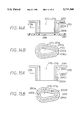
- FIG. 16A is an essential cross sectional view indicating a fifth embodiment according to the present invention
- FIG. 16B is a cross sectional view taken along line XVIB--XVIB of FIG. 16A;
- FIG. 17A is an essential sectional view indicating a sixth embodiment according to the present invention
- FIG. 17B is a cross sectional view taken along line XVIIB--XVIIB of FIG. 17A.
- FIG. 1 to FIG. 12 A first embodiment of the present invention will be described with reference to FIG. 1 to FIG. 12.
- FIGS. 1 and 2 an engine compartment A and passenger compartment B of a vehicle are separated by a partition plate C (generally referred to as a firewall, and made of sheet steel). Accordingly, a blower unit 1 of an air conditioning apparatus is disposed in a manner to be shifted in a vehicle-width direction W (in a right-hand drive vehicle, shifted to the left-hand side of the vehicle-width direction W) from a central portion of an instrument panel p within the passenger compartment B.
- L indicates a vehicle-longitudinal direction
- H indicates a vehicle-height direction
- M (see FIG. 3 and FIG. 4) indicates a central position of the vehicle-width direction W.
- the upper side of arrow L in FIG. 1 is the front (engine-compartment) side of the vehicle, and the lower side of arrow L is the rear side of the vehicle.
- the blower unit i includes an inside/outside air switching box 11 to switch and introduce the inside air in the passenger compartment inner air or the outside air outside the passenger compartment outer air.
- An outside air inlet port 12 and an inside air inlet port 13 are opened in the inside/outside air switching box 11, and an inner/outer air switching door (not illustrated) to open and close these two inlet ports 12 and 13 is installed inside the inside/outside air switching box 11.
- a filter member 11a (see FIG. 4) to remove dust or the like from air introduced from the outside air inlet port 12 and inside air inlet port 13 is incorporated within the inside/outside air switching box 11.
- a blower 14 is disposed below the inside/outside air switching box 11, as shown in FIG. 4 and FIG. 6.
- the blower 14 is composed of a centrifugal-type multiple-vane fan (scirocco fan) 15, a motor 16 for driving fan, and a scroll casing 17.
- An upper cover portion 17c is assembled to the scroll casing 17, as shown in FIG. 6, and a bellmouth-shaped intake port 18 is provided in the upper cover portion 17c.
- a rotating shaft 16a (FIG. 6) of the fan 15 is disposed substantially vertically. Air is sucked by rotation of the fan 15 from the inside/outside air switching box 11 through the filter member 11a, and passes through the bellmouth-shaped intake port 18 on the upper portion of the scroll casing 17, so that the air is blown substantially horizontally (from the left-hand side of the passenger compartment B toward the right-hand side, as is understood from FIG. 1) toward an outlet in the scroll casing 17.
- an air conditioning unit 2 into which a heat exchanger for conditioning air (described later) is incorporated, is disposed at a central portion in the vehicle-width direction W of the instrument panel p within the passenger compartment B.
- An evaporator (heat exchanger for cooling) 21 of a refrigeration cycle is disposed in a substantially horizontal state in the air conditioning unit 2, so that air which is blown by the above-described blower unit 1 flows thereinto from a lower side.
- a heater core (heat exchanger for heating) 22 is installed in a substantially horizontal state on an air downstream side of the evaporator 21.
- the heater core 22 employs engine coolant water (hot water) as a heating source.
- an air outlet mode switching portion 23 is disposed in an upper portion (air-downstream side) of the heater core 22 within the passenger compartment.
- a hot-water control valve 24 (see FIG. 6) is employed to control hot-water flow to the heater core 22 as a device for controlling temperature of conditioned air. Hot-water flow to the heater core 22 is controlled by the hot-water control valve 24, so as to regulate the amount of air heating by the heater core 22, thus controlling the temperature of air introduced into the passenger compartment.
- the air outlet mode switching portion 23 is for switching the air outlet mode to the passenger compartment, and is provided with a face air duct 25 communicated with a face (upper) air outlet (not illustrated) to supply air toward the head of a passenger in the passenger compartment, a foot air duct 27, and a defroster air duct 28 communicated with a defroster air outlet (not illustrated) to supply air toward an inner surface of the windshield.
- the foot air duct 27 is positioned at an upper portion of the air outlet mode switching portion 23 on the engine-front side (engine-compartment side), and at both ends in the vehicle-width direction W thereof, is branched into two ducts, i.e., a driver-seat-side foot air duct 27A and a passenger-seat-side foot air duct 27B. At each lower end thereof, a driver-seat-side foot air outlet 26A or a passenger-seat-side foot air outlet 26B is opened to blow air toward the foot area of the passenger in the passenger compartment.
- the air outlet mode switching portion 23 switches these plurality of air ducts 25, 27, and 28 open and closed by door means (a plate-like door, a rotary door having an arc-shaped outer peripheral surface, and a film door).
- door means a plate-like door, a rotary door having an arc-shaped outer peripheral surface, and a film door.
- the air outlet mode switching portion 23 may be of a known structure, detailed description thereof is omitted, however, in this present embodiment, as shown in FIG. 5 and FIGS. 8 to 12, the air outlet mode switching portion 23 is formed such that an upper portion of a resin upper case 29c (see FIG. 5 and FIG. 6) of the air conditioning unit 2, having an arc-shaped cross section, with a rotary door 23a rotatably installed therein.
- the rotary door 23a is formed of resin or the like in a shape having an arc-shaped peripheral surface to which an air passage opening 23b is opened, so as to rotates with a shaft portion 23c as the center.
- the shaft portion 23c is rotatably supported in a bearing hole (not illustrated) provided in the resin upper case 29c of the air conditioning unit 2.
- the plurality of air ducts 25, 27, and 28 are switched to be opened or closed by selection of the rotating position of this rotary door 23a, such that a plurality of known air outlet modes including a face (FACE) air outlet mode shown in FIG. 8, a bi-level (B/L) mode shown in FIG. 9, a foot (FOOT) air outlet mode shown in FIG. 10, a dual foot/defroster (F/D) air outlet mode shown in FIG. 11, a defroster (DEF) air outlet mode shown in FIG. 12, and so on, can be switched.
- FACE face
- B/L bi-level
- FOT foot
- F/D dual foot/defroster
- DEF defroster
- the passenger-seat-side foot air duct 27B is installed with the following characteristics.
- the passenger-seat-side foot air duct 27B extending downwardly includes a tapered expanding portion 27C at a middle portion thereof, and a cross sectional area of the tapered expanding portion 27C gradually expands.
- the tapered expanding portion 27C is branched into a plurality (three in this embodiment) of passage portions 27D, 27E, and 27F at a lower portion thereof.
- the above-described passenger-seat-side foot air duct 27B is opened at respective tip ends of these passage portions 27D, 27E, and 27F.
- the tapered expanding portion 27C includes a closed surface having three open portions 27C', 27C', and 27C'at a lower tip end thereof, so that upper ends of the passage portions 27D, 27E, and 27F are communicated (see FIG. 5) with these three open portions 27C', 27C', and 27C', respectively.
- each of passage portions 27D, 27E, and 27F is provided to pass through an outlet side path 17a of the scroll casing 17 of the blower 14, as shown in FIG. 3, FIG. 5, and FIG. 7B.
- Each of passage portions 27D, 27E, and 27F is formed so as to have a cross section having a streamline shape along air flowing through the outlet side path 17a of the scroll casing 17.
- the scroll casing 17 is formed in a logarithmic-spiral shape in which a tongue portion (nose portion) 17b thereof is taken as an origin, as shown in FIG. 3.
- the range in which the logarithmic-spiral shape is formed (a winding-angle range from the tongue portion 17b to a location 17b at which the logarithmic-spiral shape ends) is established at 240° to 270°.
- the tongue portion 17b is positioned at a location spreading by a predetermined angle from a reference circle of logarithmic-spiral shape.
- a gap "t"of a minute amount is provided between the tongue portion 17b and the other diameter of the centrifugal fan 15, and the gap "t”is normally of a size approximately 10% of the outer diameter of the centrifugal fan 15.
- a radial-type or turbo-type centrifugal fan having a high static-pressure component is employed as the centrifugal fan 15, and the centrifugal fan 15 includes a vane having a substantially arc-shaped cross section.
- the logarithmic-spiral shape of the scroll casing 17 is expressed by a configuration having a radius r according to the following equation (1).
- the outlet side path 17a of the scroll casing 17 is formed in a shape expanding in the vehicle-longitudinal direction L by expressing the logarithmic-spiral shape of the scroll casing 17 with a shape having the radius r, and as a result, the outlet side path 17a of the scroll casing 17 can be smoothly connected to an inlet side air path of the evaporator, a length L of which in the vehicle-longitudinal direction is sufficiently larger than that of the blower 14, as shown in FIG. 3.
- a temperature-operating type expansion valve 21a (FIG. 6) is provided in the evaporator 21 as a device for reducing pressure to decompress and expand the refrigerant flowing thereinto.
- the evaporator 21 is disposed in a manner to be slightly inclined from the horizontal plane to improve discharge performance of condensed water generated by cooling action. That is, the evaporator 21 is disposed in a manner to be inclined downwardly toward a front side (the right-hand side of FIG. 4) of the air blown by the blower on a lower side of the evaporator, as shown in FIG. 4.
- the inclination angle ⁇ (FIG. 4) of the evaporator 21 prefferably be in a range of 10° to 30°, and more preferably approximately 10°, so that an amount of water held by the evaporator 21 itself becomes smaller.
- a tube (not illustrated) of the evaporator 21 is disposed so as to extend in a direction identical to a blowing direction (a direction from the left-hand side to the right-hand side of FIG. 4) of the blown air, and thereby the condensed water is compressed by the blown air on the surface of the tube and is smoothly shifted to an inclination advance end (a right-hand end portion in FIG. 4).
- the condensed water generated by the evaporator 21 is discharged from a condensed liquid discharge pipe 21c provided at a lower location of the inclination advance end of the evaporator 21 at a lower end (air upstream side) of the evaporator 21.
- the pipe 21c is integrally formed at a lowest portion of a resin lower case 29a (FIG. 6).
- FIG. 6 shows an assembly structure of the apparatus in this embodiment.
- the fan 15 of the blower 15, after being integrally joined to the rotating shaft 16a of the motor 16, is disposed within the scroll casing 17 integrally formed in the resin lower case 29a, and the motor 16 is installed and fixed to the scroll casing 17 by a flange portion 16b thereof.
- the evaporator 21 is mounted on a mounting surface of the lower case 29a, and by sandwiching from the upper side with a resin middle case 29b, is fixed between the two cases 29a and 29b.
- the bellmouth-shaped intake port 18 is opened in the upper-cover portion 17c of the scroll casing 17 integrally formed with the middle case 29b, and the inside/outside air switching box 11 is disposed above this bellmouth-shaped intake port 18 and is integrally installed with the scroll casing.
- the heater core 22 and the hot-water control valve 24 are mounted on a mounting surface of the middle case 29b, and by sandwiching from the upper side with the resin upper case 29c, are fixed between the two cases 29b and 29c.
- the air outlet mode switching portion 23 is disposed on the upper case 29c, and the rotary door 23a is incorporated therewithin. Additionally, the resin foot air duct 27 formed as a separate body is joined to the upper case 29c. Similarly, although not illustrated in FIG. 6, the face air duct 25 and defroster air duct 28, which are made of resin and formed as separate bodies, are joined to the upper case 29c.
- Each of the cases 29a, 29b, and 29c, air ducts 25, 28, and 28, and inner/outer air-switching box 11 is detachably connected by metal clips having resiliency, screws, or the like.
- D 1 is a separated surface between the lower case 29a and middle case 29b, and D 1 is a separated surface between the middle case 29b and upper case 29c.
- air (arrow a in FIG. 4) which has flowed from the inside/outside air switching box 11 flows substantially horizontally (arrows b and b 1 through b 4 ) in FIG. 3 and FIG. 4) within the scroll casing 17 by the blower fan 15, passes among the three passage portions 27D, 27E, and 27F of the passenger-seat-side foot air duct 27B in the outlet side path 17a of the scroll casing 17, and flows into the lower portion of the evaporator 21 as shown by arrow c in FIG. 4. Accordingly, the blown air, after being dehumidified and cooled by the evaporator 21, flows further upwardly (arrow d), is introduced into the heater core 22, and is heated thereat.
- the hot water control valve 24 to control hot water flow to the heater core 22 is employed as a device for controlling temperature of conditioned air, and so-called a flow-regulating reheating method to obtain a desired outlet air temperature by regulating hot-water flow at this hot-water control valve 24 is employed. Accordingly, conditioned air reheated to the desired temperature by heater core 22 flows into the air outlet mode switching portion 23 of the upper-case 29c portion, as shown by arrow e, and thereat is distributed by the rotary door 23a to the predetermined ducts, as shown in FIGS. 8-12.
- Air which has flowed into the heater air duct 27 is branched into two flows in the vehicle-width direction W indicated by arrow f 1 and arrow f 2 .
- One flow f 1 passes through the driver-seat-side foot air duct 27A and is blown from the driver-seat-side foot air outlet 26A to the driver-seat foot area as indicated by arrow g 1 .
- the other flow f 2 passes through the passenger-seat-side foot air duct 27B, the tapered expanding portion 27C, and further the three passage portions 27D, 27E, and 27F, and is blown from the passenger-seat-side foot air outlet 26B to the passenger-seat foot area as indicated by arrow g 2 .
- the above operation is performed by the above-described structure, and the following effect can be obtained.
- the evaporator 21 and heater core 22 are both disposed substantially horizontally in a layout in which one is overlapping above the other, so that blown air is introduced from a lower side of these heat exchangers and air is taken out from an upper side, and therefore a blown-air duct portion in the vehicle-longitudinal direction L of the air conditioning unit 2 is not required, and the dimension of the vehicle-longitudinal direction L of the air conditioning unit 2 can be greatly reduced.
- the evaporator 21 is inclined downwardly toward a front side of the air flow direction of air blown downwardly therefrom, and the tube of the evaporator 21 is also arranged in the air flow direction (the left-hand and right-hand directions in FIG. 3 and FIG. 4), and therefore, condensed water on the surface of the tube is pushed by the blown air, smoothly gathers at the inclination advance end (the right-side end in FIG. 4) of the evaporator 21, and falls.
- condensed water is discharged to an external portion from a condensed liquid discharge pipe 21c provided below the inclination advance end of the evaporator 21. For this reason, condensed water can smoothly be discharged from the evaporator 21.
- the condensed water from the evaporator 21 flows and falls to an air upstream side, the falling condensed water is warmed by high-temperature blown air before cooled. Consequently, the outer-surface temperature of the lower case 29a does not drop greatly, and therefore, the frost of the lower case 29a is greatly reduced or is eliminated, an insulator (heat-insulating material) which is ordinarily fitted on an inner side of the case can be eliminated, and the cost can be further reduced.
- the passenger-seat-side foot air duct 27B is branched by the tapered expanding portion 27C into the three passage portions 27D, 27E, and 27F, the passenger-seat-side foot air duct 27B is opened at each of the tip end portions of these passage portions 27D, 27E, and 27F, and each of the passage portions 27D, 27E, and 27F is disposed to pass through the outlet side path 17a of the scroll casing 17 of the blower 14, and the passenger-seat-side foot air duct 27B can be disposed substantially straight downwardly from the end portion of the foot air duct 27 provided on the upper portion of the air outlet mode switching portion 23.
- each of the passage portions 27D, 27E, and 27F is formed so as to have a cross-section having a streamline shape along air flowing through the outlet side path 17a of the scroll casing 17, the increase in air flow resistance of the path 17a by passing through each of the passage portions 27D, 27E, and 27F can be suppressed to a minimum.
- FIG. 13 corresponds to FIG. 3 of the first embodiment; according to a second embodiment, a single passage portion 27G is provided as a passage portion communicating with the tapered expanding portion 27C disposed intermediately in the passenger-seat-side foot air duct 27B.
- the single passage portion 27G is disposed to pass through the outlet side path 17a of the scroll casing 17, and the passenger-seat-side foot air outlet 26B is opened at an tip end (lower-end) portion thereof.
- the passage portion 27G is formed so as to have a cross section having a streamline configuration along air flowing through the outlet side path 17a, and also the passage portion 27G is formed so as to have a cross section functioning as a scroll tongue portion of the scroll casing 17.
- a shape of the tip end portion of an air-upstream side of the passage portion 27G is formed in an arc shape having a radius R identical to a radius of curvature R of the tongue portion 17b, and a surface 27H of the passage portion 27G, a surface 27H of which faces an outer peripheral surface of the centrifugal fan 15, is formed in an identical logarithmic-spiral shape as the scroll casing 17 (i.e., a logarithmic-spiral shape having a radius r expressed by the above-described equation (1)).
- the tip portion of the passage portion 27G functions as a second tongue portion 17b', and therefore, dynamic pressure of blown air having a high dynamic-pressure component discharged from the centrifugal fan 15 can be converted more favorably to a static-pressure component by the second tongue portion 17b' at the outlet side path 17a of the scroll casing 17. For this reason, sudden enlargement loss at the outlet side path 17a of the scroll casing 17 is suppressed and an adverse influence on blowing performance can be minimized.
- the passage portions 27D, 27E, 27F, and 27G are disposed so as to pass through the outlet side path 17a of the scroll casing 17 of the blower, and therefore, when hot air heated by the heater core 22 passes through the passage portions 27D, 27E, 27F, and 27G, the hot air exchanges heat with low-temperature air flowing through the outlet side path 17a and temperature thereof is reduced.
- temperature of hot air blown from the passenger-seat-side foot air duct 27B when the outside air temperature is low, may be lower than a preferable temperature in view of the heating feeling.
- a heat transfer coefficient at the duct wall is lowered by forming the duct wall of the passage portions 27D, 27E, 27F, and 27G in at least a double-layer duct structure and by forming an heat insulating air layer in an intermediate portion of the double-layer duct structure, thereby suppressing heat exchange between the foregoing hot air and low-temperature air to a minute amount.
- the resin lower case 29b shown in FIG. 6 is separated into an upper-side first case 290 and a lower-side second case 291 as shown in FIG. 14, and the upper-side first case 290 is formed in a multiple-layer cross-sectional shape of two layers so as to be joined on the lower-side second case 291.
- an heat insulating air layer 290c is formed between an outer peripheral wall 290a and an inner peripheral wall 290b of the upper-side first case 290.
- the heat transfer coefficient at the duct wall of the passage portions 27D through 27G is lowered, and heat exchange between the hot air and low-temperature air can be suppressed to a minute amount.
- a plurality of ribs 290d interconnected between the outer peripheral wall 290a and inner peripheral wall 290b of the upper-side first case 290 as in the above-described third embodiment are integrally formed.
- the rigidity of the upper-side first case 290 is improved, and the shape of the passage portions 27D through 27G (i.e., the interval between the inner and outer walls 290a and 290b) are stabilized by these ribs 290d.
- an outer peripheral wall 291a corresponding to the outer peripheral wall 290a as in the third embodiment is formed on the lower-side second case 291, and the heat insulating air layer 290c is formed between the outer peripheral wall 291a and the inner peripheral wall 290b of the upper-side first case 290.
- a plurality of ribs 290e protruding to an outer peripheral side are integrally on the inner peripheral wall 290b of the upper-side first case 290, and the interval between the inner and outer walls 290a and 290b is stabilized by these ribs 290e.
- the present invention may be embodied in various modes other than the embodiments described and illustrated hereinabove.
- the passage portions 27D through 27G of the passenger-seat-side foot air ductformed in formed in the lower case 29a in each of the above-described embodiments it is also acceptable to form these passage portions 27D to 27G in both the lower case 29a and the middle case 29b.
- the double-layer duct-wall structure of the passage portions 27D to 27G indicated in FIGS. 14 to FIG. 17 is also acceptable for the double-layer duct-wall structure of the passage portions 27D to 27G indicated in FIGS. 14 to FIG. 17 to be formed in both the lower case 29a and the middle case 29b. Needless to say, it is also acceptable for the passage portions 27D to 27G to have a multiple-layer duct-wall structure of three or more layers.
- an air mixing door may be employed as the device for controlling temperature instead of the flow-regulating reheating method utilizing the hot-water control valve 24, and a plate door may be utilized instead of the rotary door 23a as the device for switching passages of the air outlet mode switching portion 23.
Landscapes
- Physics & Mathematics (AREA)
- Thermal Sciences (AREA)
- Engineering & Computer Science (AREA)
- Mechanical Engineering (AREA)
- Air-Conditioning For Vehicles (AREA)
Applications Claiming Priority (2)
| Application Number | Priority Date | Filing Date | Title |
|---|---|---|---|
| JP7-170970 | 1995-07-06 | ||
| JP17097095A JP3422136B2 (ja) | 1995-07-06 | 1995-07-06 | 自動車用空調装置 |
Publications (1)
| Publication Number | Publication Date |
|---|---|
| US5711368A true US5711368A (en) | 1998-01-27 |
Family
ID=15914747
Family Applications (1)
| Application Number | Title | Priority Date | Filing Date |
|---|---|---|---|
| US08/675,597 Expired - Fee Related US5711368A (en) | 1995-07-06 | 1996-07-03 | Air conditioning apparatus for a vehicle |
Country Status (3)
| Country | Link |
|---|---|
| US (1) | US5711368A (ja) |
| JP (1) | JP3422136B2 (ja) |
| DE (1) | DE19627018B4 (ja) |
Cited By (27)
| Publication number | Priority date | Publication date | Assignee | Title |
|---|---|---|---|---|
| US5975422A (en) * | 1995-12-20 | 1999-11-02 | Saab Automobile Ab | Climatizing arrangement and a method for controlling the same |
| US5992506A (en) * | 1997-03-13 | 1999-11-30 | Denso Corporation | Air conditioning apparatus for vehicle |
| US6019163A (en) * | 1997-09-25 | 2000-02-01 | Denso Corporation | Air conditioning apparatus for vehicle with air deflectors on air-mix doors |
| US6062298A (en) * | 1996-07-27 | 2000-05-16 | Halla Climate Control Corporation | Case of air conditioning system |
| US6244335B1 (en) * | 1998-02-19 | 2001-06-12 | Denso Corporation | Vehicular air-conditioner |
| US20020014331A1 (en) * | 2000-08-01 | 2002-02-07 | Ian Bendell | Heating and air-conditioning system for a motor vehicle |
| US6382518B1 (en) * | 1999-10-18 | 2002-05-07 | Denso Corporation | Vehicle air conditioner with side face opening |
| US6422301B1 (en) * | 2000-08-14 | 2002-07-23 | Delphi Technologies, Inc. | Dual functional drain for a heating, ventilating, and air conditioning assembly |
| WO2003022609A1 (fr) * | 2001-09-06 | 2003-03-20 | Japan Climate Systems Corporation | Dispositif de climatisation conçu pour un vehicule |
| US6598670B1 (en) * | 1999-11-11 | 2003-07-29 | Denso Corporation | Vehicle air-conditioner |
| US6601639B2 (en) * | 1999-02-04 | 2003-08-05 | Denso Corporation | Vehicle air conditioner with attachment and detachment of evaporator |
| US6796368B1 (en) * | 1997-08-11 | 2004-09-28 | Denso Corporation | Air conditioning apparatus for vehicle |
| US20040194948A1 (en) * | 2003-02-13 | 2004-10-07 | Kazuji Shibata | Automotive air conditioning system |
| US6877550B2 (en) * | 2000-07-21 | 2005-04-12 | Denso Corporation | Vehicle air conditioner |
| US6942564B1 (en) * | 2004-02-27 | 2005-09-13 | Denso International America, Inc. | Passenger foot duct |
| US20050217295A1 (en) * | 2004-01-28 | 2005-10-06 | Thomas Alberternst | Multiple zoned air conditioning system |
| US20050229619A1 (en) * | 2002-12-05 | 2005-10-20 | Behr France S.A.R.L. | Water tank arrangement, particularly in connection with a heater or air conditioner for a motor vehicle |
| US20060094346A1 (en) * | 2004-11-03 | 2006-05-04 | Visteon Global Technologies, Inc. | Air stream mixing conduit in an air handling module |
| US20070000640A1 (en) * | 2005-07-01 | 2007-01-04 | Valeo Klimasysteme Gmbh | System housing, in particular for a heating, ventilating and/or air-conditioning system of a vehicle |
| US20070066211A1 (en) * | 2003-05-16 | 2007-03-22 | Behr Gmbh & Co. Kg | Air distributor device or air mixing device |
| US20070107892A1 (en) * | 2005-11-16 | 2007-05-17 | Calsonic Kansei Corporation | Vehicular air conditioner |
| US20080032617A1 (en) * | 2004-09-10 | 2008-02-07 | Behr France Rouffach Sas | Modular Motor Vehicle Air-Conditioning Unit |
| US20170001491A1 (en) * | 2015-07-03 | 2017-01-05 | Valeo Japan Co., Ltd. | Vehicular air conditioner and vehicle equipped with vehicular air conditioner |
| EP2969673A4 (en) * | 2013-04-28 | 2017-03-08 | BYD Company Limited | Defroster and vehicle having the same |
| US10330103B2 (en) | 2015-06-10 | 2019-06-25 | Mahle International Gmbh | Centrifugal blower |
| US20230016878A1 (en) * | 2019-12-20 | 2023-01-19 | Gentherm Incorporated | Air Distribution Device For A Vehicle Seat |
| US20240253420A1 (en) * | 2021-12-29 | 2024-08-01 | Hanon Systems | Air-conditioning apparatus for vehicle |
Families Citing this family (2)
| Publication number | Priority date | Publication date | Assignee | Title |
|---|---|---|---|---|
| DE19807002B4 (de) * | 1997-02-21 | 2006-11-02 | Denso Corp., Kariya | Klimaanlage für ein Fahrzeug |
| JP3577919B2 (ja) * | 1997-11-18 | 2004-10-20 | 日産自動車株式会社 | 車両用空調装置 |
Citations (14)
| Publication number | Priority date | Publication date | Assignee | Title |
|---|---|---|---|---|
| US2213018A (en) * | 1938-06-09 | 1940-08-27 | Modine Mfg Co | Air conditioner for automobiles |
| US2295750A (en) * | 1938-02-14 | 1942-09-15 | Nash Kelvinator Corp | Vehicular air conditioning system |
| GB986663A (en) * | 1960-03-12 | 1965-03-17 | Firth Cleveland Ltd | Improvements relating to the air conditioning and heating of vehicles |
| US3918270A (en) * | 1974-07-15 | 1975-11-11 | Don P Dixon | Automobile air conditioning system |
| JPS5682628A (en) * | 1979-12-11 | 1981-07-06 | Nissan Motor Co Ltd | Air-conditioning device for automobile |
| US4709751A (en) * | 1984-08-20 | 1987-12-01 | Nissan Motor Company, Limited | Vehicular air conditioner with defogging feature |
| US4958504A (en) * | 1988-06-17 | 1990-09-25 | Matsushita Electric Industrial Co., Ltd. | Air conditioning apparatus for use in automobile |
| US4976309A (en) * | 1988-03-04 | 1990-12-11 | Zaporozhsky Avtomobilny ZaVod "Kommunar" (Proizvodstvennoe Objedinenie "AV to ZAZ" | Air conditioner for a vehicle |
| US5012859A (en) * | 1988-01-21 | 1991-05-07 | Sanden Corporation | Automotive air conditioning system |
| US5074121A (en) * | 1989-10-09 | 1991-12-24 | Valeo | Air conditioning installation for an automotive vehicle |
| US5086830A (en) * | 1989-08-31 | 1992-02-11 | Mercedes-Benz Ag | Air-conditioning system for motor vehicles |
| JPH053365A (ja) * | 1991-06-25 | 1993-01-08 | Nec Corp | 分布帰還型レーザ |
| JPH06227592A (ja) * | 1993-01-28 | 1994-08-16 | Mitsubishi Heavy Ind Ltd | 充填機のバルブ開閉装置 |
| JPH06240362A (ja) * | 1993-02-15 | 1994-08-30 | Sumitomo Metal Ind Ltd | 継目無鋼管の加工熱処理における温度制御方法 |
Family Cites Families (1)
| Publication number | Priority date | Publication date | Assignee | Title |
|---|---|---|---|---|
| DE4232706C1 (en) * | 1992-09-30 | 1993-08-19 | Mercedes-Benz Aktiengesellschaft, 7000 Stuttgart, De | Air conditioning plant for motor vehicle interior - has air guide housing with evaporator and heat exchangers in a row, across direction of travel |
-
1995
- 1995-07-06 JP JP17097095A patent/JP3422136B2/ja not_active Expired - Fee Related
-
1996
- 1996-07-03 US US08/675,597 patent/US5711368A/en not_active Expired - Fee Related
- 1996-07-04 DE DE19627018A patent/DE19627018B4/de not_active Expired - Fee Related
Patent Citations (14)
| Publication number | Priority date | Publication date | Assignee | Title |
|---|---|---|---|---|
| US2295750A (en) * | 1938-02-14 | 1942-09-15 | Nash Kelvinator Corp | Vehicular air conditioning system |
| US2213018A (en) * | 1938-06-09 | 1940-08-27 | Modine Mfg Co | Air conditioner for automobiles |
| GB986663A (en) * | 1960-03-12 | 1965-03-17 | Firth Cleveland Ltd | Improvements relating to the air conditioning and heating of vehicles |
| US3918270A (en) * | 1974-07-15 | 1975-11-11 | Don P Dixon | Automobile air conditioning system |
| JPS5682628A (en) * | 1979-12-11 | 1981-07-06 | Nissan Motor Co Ltd | Air-conditioning device for automobile |
| US4709751A (en) * | 1984-08-20 | 1987-12-01 | Nissan Motor Company, Limited | Vehicular air conditioner with defogging feature |
| US5012859A (en) * | 1988-01-21 | 1991-05-07 | Sanden Corporation | Automotive air conditioning system |
| US4976309A (en) * | 1988-03-04 | 1990-12-11 | Zaporozhsky Avtomobilny ZaVod "Kommunar" (Proizvodstvennoe Objedinenie "AV to ZAZ" | Air conditioner for a vehicle |
| US4958504A (en) * | 1988-06-17 | 1990-09-25 | Matsushita Electric Industrial Co., Ltd. | Air conditioning apparatus for use in automobile |
| US5086830A (en) * | 1989-08-31 | 1992-02-11 | Mercedes-Benz Ag | Air-conditioning system for motor vehicles |
| US5074121A (en) * | 1989-10-09 | 1991-12-24 | Valeo | Air conditioning installation for an automotive vehicle |
| JPH053365A (ja) * | 1991-06-25 | 1993-01-08 | Nec Corp | 分布帰還型レーザ |
| JPH06227592A (ja) * | 1993-01-28 | 1994-08-16 | Mitsubishi Heavy Ind Ltd | 充填機のバルブ開閉装置 |
| JPH06240362A (ja) * | 1993-02-15 | 1994-08-30 | Sumitomo Metal Ind Ltd | 継目無鋼管の加工熱処理における温度制御方法 |
Cited By (37)
| Publication number | Priority date | Publication date | Assignee | Title |
|---|---|---|---|---|
| US5975422A (en) * | 1995-12-20 | 1999-11-02 | Saab Automobile Ab | Climatizing arrangement and a method for controlling the same |
| US6062298A (en) * | 1996-07-27 | 2000-05-16 | Halla Climate Control Corporation | Case of air conditioning system |
| US5992506A (en) * | 1997-03-13 | 1999-11-30 | Denso Corporation | Air conditioning apparatus for vehicle |
| US6796368B1 (en) * | 1997-08-11 | 2004-09-28 | Denso Corporation | Air conditioning apparatus for vehicle |
| US6019163A (en) * | 1997-09-25 | 2000-02-01 | Denso Corporation | Air conditioning apparatus for vehicle with air deflectors on air-mix doors |
| US6244335B1 (en) * | 1998-02-19 | 2001-06-12 | Denso Corporation | Vehicular air-conditioner |
| US6601639B2 (en) * | 1999-02-04 | 2003-08-05 | Denso Corporation | Vehicle air conditioner with attachment and detachment of evaporator |
| US6382518B1 (en) * | 1999-10-18 | 2002-05-07 | Denso Corporation | Vehicle air conditioner with side face opening |
| US6598670B1 (en) * | 1999-11-11 | 2003-07-29 | Denso Corporation | Vehicle air-conditioner |
| US6877550B2 (en) * | 2000-07-21 | 2005-04-12 | Denso Corporation | Vehicle air conditioner |
| US7156166B2 (en) * | 2000-08-01 | 2007-01-02 | Behr Gmbh & Co. | Heating and air-conditioning system for a motor vehicle |
| US20020014331A1 (en) * | 2000-08-01 | 2002-02-07 | Ian Bendell | Heating and air-conditioning system for a motor vehicle |
| US6422301B1 (en) * | 2000-08-14 | 2002-07-23 | Delphi Technologies, Inc. | Dual functional drain for a heating, ventilating, and air conditioning assembly |
| WO2003022609A1 (fr) * | 2001-09-06 | 2003-03-20 | Japan Climate Systems Corporation | Dispositif de climatisation conçu pour un vehicule |
| CN1703329B (zh) * | 2001-09-06 | 2012-06-20 | 日本空调系统股份有限公司 | 车辆用空调装置 |
| US20050229619A1 (en) * | 2002-12-05 | 2005-10-20 | Behr France S.A.R.L. | Water tank arrangement, particularly in connection with a heater or air conditioner for a motor vehicle |
| US20040194948A1 (en) * | 2003-02-13 | 2004-10-07 | Kazuji Shibata | Automotive air conditioning system |
| US7281574B2 (en) * | 2003-02-13 | 2007-10-16 | Denso Corporation | Automotive air conditioning system |
| US20070066211A1 (en) * | 2003-05-16 | 2007-03-22 | Behr Gmbh & Co. Kg | Air distributor device or air mixing device |
| US20050217295A1 (en) * | 2004-01-28 | 2005-10-06 | Thomas Alberternst | Multiple zoned air conditioning system |
| US7434612B2 (en) * | 2004-01-28 | 2008-10-14 | Visteon Global Technologies, Inc. | Multiple zoned air conditioning system |
| US20050202772A1 (en) * | 2004-02-27 | 2005-09-15 | Tim Roland | Passenger foot duct |
| US6942564B1 (en) * | 2004-02-27 | 2005-09-13 | Denso International America, Inc. | Passenger foot duct |
| US20080032617A1 (en) * | 2004-09-10 | 2008-02-07 | Behr France Rouffach Sas | Modular Motor Vehicle Air-Conditioning Unit |
| US20060094346A1 (en) * | 2004-11-03 | 2006-05-04 | Visteon Global Technologies, Inc. | Air stream mixing conduit in an air handling module |
| US7074122B2 (en) | 2004-11-03 | 2006-07-11 | Visteon Global Technologies, Inc. | Air stream mixing conduit in an air handling module |
| US20070000640A1 (en) * | 2005-07-01 | 2007-01-04 | Valeo Klimasysteme Gmbh | System housing, in particular for a heating, ventilating and/or air-conditioning system of a vehicle |
| US7572178B2 (en) * | 2005-07-01 | 2009-08-11 | Valeo Klimasysteme Gmbh | System housing, in particular for a heating, ventilating and/or air-conditioning system of a vehicle |
| US20070107892A1 (en) * | 2005-11-16 | 2007-05-17 | Calsonic Kansei Corporation | Vehicular air conditioner |
| US7905278B2 (en) * | 2005-11-16 | 2011-03-15 | Calsonic Kansei Corporation | Vehicular air conditioner |
| EP2969673A4 (en) * | 2013-04-28 | 2017-03-08 | BYD Company Limited | Defroster and vehicle having the same |
| US10059306B2 (en) | 2013-04-28 | 2018-08-28 | Byd Company Limited | Defroster and a vehicle having the same |
| US10330103B2 (en) | 2015-06-10 | 2019-06-25 | Mahle International Gmbh | Centrifugal blower |
| US20170001491A1 (en) * | 2015-07-03 | 2017-01-05 | Valeo Japan Co., Ltd. | Vehicular air conditioner and vehicle equipped with vehicular air conditioner |
| US20230016878A1 (en) * | 2019-12-20 | 2023-01-19 | Gentherm Incorporated | Air Distribution Device For A Vehicle Seat |
| US12441219B2 (en) * | 2019-12-20 | 2025-10-14 | Gentherm Incorporated | Air distribution device for a vehicle seat |
| US20240253420A1 (en) * | 2021-12-29 | 2024-08-01 | Hanon Systems | Air-conditioning apparatus for vehicle |
Also Published As
| Publication number | Publication date |
|---|---|
| JP3422136B2 (ja) | 2003-06-30 |
| JPH0920125A (ja) | 1997-01-21 |
| DE19627018A1 (de) | 1997-01-09 |
| DE19627018B4 (de) | 2004-08-26 |
Similar Documents
| Publication | Publication Date | Title |
|---|---|---|
| US5711368A (en) | Air conditioning apparatus for a vehicle | |
| US6044656A (en) | Automotive air conditioner | |
| US7871316B2 (en) | Passage opening and closing device | |
| JP2970490B2 (ja) | 自動車用空調装置 | |
| US6743090B2 (en) | Vehicle air conditioner with rotary door | |
| US6749008B2 (en) | Vehicle air-conditioning system | |
| US20010017203A1 (en) | Automotive air-conditioner having scroll casing | |
| US20020011325A1 (en) | Vehicle air conditioner | |
| US20070158047A1 (en) | Air conditioner for vehicle | |
| JP3232913B2 (ja) | 自動車用空調装置 | |
| JP4894447B2 (ja) | 車両用空調装置 | |
| JPH10181336A (ja) | 車両用空調装置 | |
| KR20220068552A (ko) | 차량용 공조장치 | |
| JP3799647B2 (ja) | 自動車用空調装置 | |
| JP3785980B2 (ja) | 車両用空調装置 | |
| KR20150021720A (ko) | 차량용 공조장치 | |
| US6877550B2 (en) | Vehicle air conditioner | |
| JP2005349942A (ja) | 車両用空調装置 | |
| JP4433169B2 (ja) | 車両用空気調和装置 | |
| JPH10181332A (ja) | 空気通路用ドア装置および車両用空調装置 | |
| US20020129931A1 (en) | Air conditioner and arrangement structure in vehicle | |
| JP3969232B2 (ja) | 車両用空調装置 | |
| JP2006321361A (ja) | ベント開口部構成部材及びこれを用いた車両用空調ユニット | |
| JP2001030739A (ja) | ダンパ構造、車両用空気調和ユニット及び車両用空気調和装置 | |
| KR102512379B1 (ko) | 차량용 공조장치 |
Legal Events
| Date | Code | Title | Description |
|---|---|---|---|
| AS | Assignment |
Owner name: NIPPONDENSO CO., LTD., JAPAN Free format text: ASSIGNMENT OF ASSIGNORS INTEREST;ASSIGNORS:ITO, KOJI;KAMEOKA, TERUHIKO;TANAKA, HISASHI;AND OTHERS;REEL/FRAME:008188/0309;SIGNING DATES FROM 19960906 TO 19960916 |
|
| CC | Certificate of correction | ||
| FEPP | Fee payment procedure |
Free format text: PAYOR NUMBER ASSIGNED (ORIGINAL EVENT CODE: ASPN); ENTITY STATUS OF PATENT OWNER: LARGE ENTITY |
|
| FPAY | Fee payment |
Year of fee payment: 4 |
|
| FPAY | Fee payment |
Year of fee payment: 8 |
|
| REMI | Maintenance fee reminder mailed | ||
| LAPS | Lapse for failure to pay maintenance fees | ||
| STCH | Information on status: patent discontinuation |
Free format text: PATENT EXPIRED DUE TO NONPAYMENT OF MAINTENANCE FEES UNDER 37 CFR 1.362 |
|
| FP | Lapsed due to failure to pay maintenance fee |
Effective date: 20100127 |