US5674083A - ESD protected electrical connector - Google Patents
ESD protected electrical connector Download PDFInfo
- Publication number
- US5674083A US5674083A US08/561,648 US56164895A US5674083A US 5674083 A US5674083 A US 5674083A US 56164895 A US56164895 A US 56164895A US 5674083 A US5674083 A US 5674083A
- Authority
- US
- United States
- Prior art keywords
- housing
- conductive member
- electrical connector
- contacts
- set forth
- Prior art date
- Legal status (The legal status is an assumption and is not a legal conclusion. Google has not performed a legal analysis and makes no representation as to the accuracy of the status listed.)
- Expired - Lifetime
Links
Images


Classifications
-
- H—ELECTRICITY
- H01—ELECTRIC ELEMENTS
- H01R—ELECTRICALLY-CONDUCTIVE CONNECTIONS; STRUCTURAL ASSOCIATIONS OF A PLURALITY OF MUTUALLY-INSULATED ELECTRICAL CONNECTING ELEMENTS; COUPLING DEVICES; CURRENT COLLECTORS
- H01R13/00—Details of coupling devices of the kinds covered by groups H01R12/70 or H01R24/00 - H01R33/00
- H01R13/648—Protective earth or shield arrangements on coupling devices, e.g. anti-static shielding
- H01R13/6485—Electrostatic discharge protection
Definitions
- the present invention relates to the field of electrical connectors, and more particularly to connectors having protection against electrostatic potential discharge (ESD).
- ESD electrostatic potential discharge
- Certain electrical connectors are used in environments where an electrostatic potential commonly develops between the apparati to which each of a matable pair of electrical connectors is mounted, with damaging consequences to sensitive electronic components of the apparati upon uncontrolled discharge of this potential if the potential is great enough.
- An example of this is concerned with an electronic apparatus such as a television set to which a peripheral apparatus is to be electrically connected by means of a cable harness at an input/output port of the set; discharge of the potential can occur along signal lines upon mating of the cable and port connectors, with the surge possibly capable of damaging the electronic components to which the signal lines lead.
- the electrical connector of the present invention includes a plurality of contacts secured in a dielectric housing to extend from a mating face to an opposed mounting face to be mounted to a circuit element such as a circuit board or the like, with exposed contact sections at least at the mounting face for being electrically connected to circuits of the board.
- a conductive portion of the connector is provided such as a conductive member affixed to the connector, to be spaced slightly from all contacts to define spark gaps, and includes a portion adapted to be connected to a ground circuit of the circuit element to discharge ESD on a continuing basis after the connector is mated to another connector such as a cable connector of a cable of another electronic unit.
- the present invention when mounted at the input/output port of an electronic apparatus and connected to chassis ground, provides ESD protection to the apparatus even when unmated to a mating connector, especially important when such a connector has no ground shield surrounding the dielectric housing and the signal contacts are particularly susceptible to receipt of ESD from another body.
- the conductive member is affixed to the mounting face and has a body section extending transversely between board-mounting sections at respective ends, with the board-mounting sections extending from the mounting face to be received into mounting holes of the circuit board, providing the means for mounting the connector to the circuit element.
- the body section extends by exposed portions of the contacts, and edges of the body section preferably include protuberances adjacent the contacts and spaced therefrom a selected short distance to act as ESD concentrators that will attract the discharge from all contacts of the connector; the board-mounting sections are electrically connected to a ground path of the circuit board that will transmit the discharge to chassis ground.
- the single-piece conductive member prefferably serves as a board-mounting device.
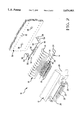
- FIGS. 1 and 2 are isometric assembly and exploded views of the connector containing the present invention
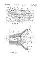
- FIG. 3 is a conductive member facilitating innocuous electrostatic discharge in accordance with the present invention.
- FIG. 4 is a plan view of the board-mounting face of the connector of FIGS. 1 and 2;
- FIG. 5 is a cross-sectional view of the connector taken along lines 5--5 of FIG. 4;
- FIG. 6 is an isometric view of the board-mounting face of the connector with the conductive member of FIG. 3 positioned to be assembled thereto;
- FIGS. 7 and 8 are isometric views of the board-mounting face of the connector, with FIG. 8 being an enlargement illustrating the board-mounting section of the conductive member of FIG. 3, and several spark gaps between the conductive member and several terminals of the connector.
- Electrical connector 10 includes a dielectric housing 12 with a two-row array of contacts 14 mounted in respective passageways 16 (FIGS. 4 and 5) and extending from first contact sections 18 exposed in a plug-receiving cavity 20 at connector mating face 22, to second contact sections 24 exposed at connector mounting face 26. Also seen in FIGS. 1 and 2 are latching members 28 for securing connector 10 to a mating connector (not shown).
- Contacts 14 are arrayed such that first contact sections 18 are positioned in a first two-row arrangement and spacing, and second contact sections 24 are positioned in a second two-row arrangement and spacing and are adapted to be inserted into through-holes 30 of circuit element 32 to provide electrical connections with discrete circuits of the element 30.
- Contacts 14 include body sections 34 dimensioned and shaped to extend between first and second contact sections 18,24.
- Body sections 34 include retention sections 38 that cooperate with portions of passageways 16 to establish an interference fit, for retention of contacts 14 within connector 10, such as by being widened to be slightly greater than the passageway dimension thereat while permitting insertion of the narrower portion of the contact to be inserted therepast.
- second contact sections 24 are shown preferably to include widened portions 40 for retaining second contact sections 24 in precise positions in T-shaped slots 42 of housing 12 (FIGS. 6 to 8), facilitating insertion into through-holes 30 of circuit element 30 during board mounting.
- Conductive member 50 of FIGS. 2 to 8 includes a conductive body 52 with tabs 54 extending from ends thereof and concluding in board-mounting sections 56 to be received into mounting holes 36 of circuit element 32 in a force-fit, for retention of connector 10 to circuit element 32.
- Protrusions 58 are seen provided along side edges 60 of conductive body 52 in the form of teeth, whose purpose will be described below.
- an embossment 62 is formed along conductive body 52 for strength.
- Flange portions 66 of housing 12 are provided proximate each end of the housing along board-mounting face 24.
- Flange portions 66 include T-shaped slots 68 having ears 70 associated with side edges 72 of tabs 54 of conductive member 50, and with openings 74 in communication with open area 76 between flange portions 66 for conductive body 52 to extend therethrough into open area 76.
- dome-shaped embossments 64 engageable with opposed side walls of slots 68 into which tabs 54 are inserted to define an interference fit.
- conductive body 52 extends past and near all contacts 14 along mounting face 26, with protrusions 58 associated with respective contacts 14 along body sections 34, such as at retention sections 38 exposed at entrances to passageways 16 of housing 12.
- a small finite distance is maintained at spark gap 80 between protrusions 58 and contacts 14, which distance may be incremental and just sufficient to assuredly not engage the contacts.
- a nonconductive or dielectric film or coating may be provided on either the contacts or conductive member 50 adjacent spark gap 80 which may then be sufficiently slit or perforated to allow metal to directly face metal to allow discharge of the electrostatic potential, with the film or coating sufficient to assuredly prevent engagement of the metal surfaces.
- Such coating may be an oxide layer on the conductive member, or may be a thin film of for example polyester or polytetrafluoroethylene.
- a spark gap may also be defined without protrusions being formed on the conductive member. It is seen that the conductive member of the present invention may easily be stamped and formed from a strip of metal such as tin-plated brass, and easily assembled to the connector housing.
- FIGS. 6 to 8 illustrate that contacts 14 vary in shape and length along the intermediate portions of body sections 34 between widened portions 40 and retention sections 38 in order to provide a transition between the close spacing of contact sections 18 along mating face 22 and the relatively substantially spaced contact sections 24 along the mounting face 26 required of certain circuit elements such as circuit boards with stamped through holes.
- a clearing is provided between passageways 16 and the T-shaped slots 42 containing widened portions 40, preferably a flattened surface along which the intermediate portions of body sections 34 extend freely while being secured at widened portions 40 and retention sections 38.
- the benefits of the present invention are especially useful where connector 10 is to be mounted to an electronic apparatus at an input/output port, to allow connection of an electrical cable of a peripheral electronic unit for signal transmission between the apparatus and the unit, a scenario commonly understood to generate electrostatic potential therebetween needing to be safely discharged.
- the present invention is continuously operative to discharge the potential after mating of the apparatus connector and the cable connector, unlike many ESD arrangements that are only operative at the instant of connector mating.
- the conductive member also contains the board-mounting portion of the connector simplifying assembly thereof and reducing the inventory of parts, where the board-mounting portion is grounded to a ground circuit of the circuit board.
- the conductive member may be separate from the board-mounting portion so long as a ground connection is established to chassis ground of the apparatus.
- ESD protection is provided in a connector with no shield therearound, when the connector is mounted at an input/output port of an apparatus and is in an unmated condition and thus susceptible to ESD from a variety of sources.
Landscapes
- Details Of Connecting Devices For Male And Female Coupling (AREA)
- Elimination Of Static Electricity (AREA)
Priority Applications (6)
| Application Number | Priority Date | Filing Date | Title |
|---|---|---|---|
| US08/561,648 US5674083A (en) | 1995-11-22 | 1995-11-22 | ESD protected electrical connector |
| CN96180178A CN1226346A (zh) | 1995-11-22 | 1996-11-15 | 防静电电位放电的电接头 |
| PCT/US1996/018409 WO1997019497A1 (en) | 1995-11-22 | 1996-11-15 | Esd protected electrical connector |
| EP96940492A EP0862802A1 (en) | 1995-11-22 | 1996-11-15 | Esd protected electrical connector |
| KR1019980708605A KR19990072230A (ko) | 1995-11-22 | 1996-11-15 | Esd 보호형 전기 커넥터 |
| JP51980797A JP2001520794A (ja) | 1995-11-22 | 1996-11-15 | 静電位放電から保護された電気コネクタ |
Applications Claiming Priority (1)
| Application Number | Priority Date | Filing Date | Title |
|---|---|---|---|
| US08/561,648 US5674083A (en) | 1995-11-22 | 1995-11-22 | ESD protected electrical connector |
Publications (1)
| Publication Number | Publication Date |
|---|---|
| US5674083A true US5674083A (en) | 1997-10-07 |
Family
ID=24242846
Family Applications (1)
| Application Number | Title | Priority Date | Filing Date |
|---|---|---|---|
| US08/561,648 Expired - Lifetime US5674083A (en) | 1995-11-22 | 1995-11-22 | ESD protected electrical connector |
Country Status (6)
| Country | Link |
|---|---|
| US (1) | US5674083A (ja) |
| EP (1) | EP0862802A1 (ja) |
| JP (1) | JP2001520794A (ja) |
| KR (1) | KR19990072230A (ja) |
| CN (1) | CN1226346A (ja) |
| WO (1) | WO1997019497A1 (ja) |
Cited By (21)
| Publication number | Priority date | Publication date | Assignee | Title |
|---|---|---|---|---|
| EP0851540A2 (en) * | 1996-12-30 | 1998-07-01 | Molex Incorporated | Board mounted electrical connector with multi-function board lock |
| US6056603A (en) * | 1998-04-08 | 2000-05-02 | The Whitaker Corporation | Sacrificial plastic rib for contact retention |
| US6064094A (en) * | 1998-03-10 | 2000-05-16 | Oryx Technology Corporation | Over-voltage protection system for integrated circuits using the bonding pads and passivation layer |
| US6095863A (en) * | 1998-12-22 | 2000-08-01 | Hon Hai Precision Ind. Co., Ltd. | Electrical card connector having a grounding shield |
| US6116949A (en) * | 1999-01-13 | 2000-09-12 | The Whitaker Corporation | Electrostatic protection cover for electrical connector |
| US6172590B1 (en) | 1996-01-22 | 2001-01-09 | Surgx Corporation | Over-voltage protection device and method for making same |
| US20020001160A1 (en) * | 2000-04-20 | 2002-01-03 | Reinhold Berberich | Overvoltage protection device |
| US6373719B1 (en) | 2000-04-13 | 2002-04-16 | Surgx Corporation | Over-voltage protection for electronic circuits |
| US20030076078A1 (en) * | 2001-09-27 | 2003-04-24 | Balu Balakrishnan | Method and apparatus for maintaining a constant load current with line voltage in a switch mode power supply |
| FR2831336A1 (fr) * | 2001-10-18 | 2003-04-25 | Peugeot Citroen Automobiles Sa | Dispositif de protection contre des decharges electrostatiques d'un connecteur electrique |
| US6683773B2 (en) | 2000-11-30 | 2004-01-27 | John Mezzalingua Associates, Inc. | High voltage surge protection element for use with CATV coaxial cable connectors |
| US20040057186A1 (en) * | 2000-11-30 | 2004-03-25 | Chawgo Shawn M. | Apparatus for high surge voltage protection |
| EP1439617A1 (de) * | 2003-01-18 | 2004-07-21 | Audi Ag | Steckvorrichtung zur Erhöhung der ESD-Festigkeit |
| US20060024986A1 (en) * | 2004-07-28 | 2006-02-02 | International Business Machines Corporation | Electrostatic discharge dissipative sockets |
| US20060216978A1 (en) * | 2005-03-10 | 2006-09-28 | Avision Inc. | Electrical connector capable of interrupting an ESD path |
| US20090251841A1 (en) * | 2008-04-04 | 2009-10-08 | Littelfuse, Inc. | Incorporating electrostatic protection into miniature connectors |
| US20100216335A1 (en) * | 2009-02-24 | 2010-08-26 | Terry Cobb | Communications Patching Devices that Include Integrated Electronic Static Discharge Circuits and Related Methods |
| US8395875B2 (en) | 2010-08-13 | 2013-03-12 | Andrew F. Tresness | Spark gap apparatus |
| US20140120780A1 (en) * | 2012-10-31 | 2014-05-01 | Jae Electronics, Inc. | Connector |
| US9583884B1 (en) | 2016-02-26 | 2017-02-28 | Northrop Grumman Systems Corporation | Electrostatic discharge (ESD) safe connector insert |
| US11025007B2 (en) * | 2017-07-28 | 2021-06-01 | Iriso Electronics Co., Ltd. | Electronic component |
Families Citing this family (5)
| Publication number | Priority date | Publication date | Assignee | Title |
|---|---|---|---|---|
| JP2009009728A (ja) * | 2007-06-26 | 2009-01-15 | Taiko Denki Co Ltd | レセプタクル |
| JP2011204483A (ja) * | 2010-03-25 | 2011-10-13 | Denso Corp | 電気コネクタおよびそれが実装された回路基板 |
| CN102904115B (zh) * | 2012-09-27 | 2015-08-26 | 珠海德百祺科技有限公司 | 具有esd防护功能的连接器 |
| DE102017214599A1 (de) * | 2017-08-22 | 2019-02-28 | Robert Bosch Gmbh | Anschlussvorrichtung für einen Sensor |
| CN215813334U (zh) * | 2021-03-02 | 2022-02-11 | 华为技术有限公司 | 电子装置、终端设备及雷达 |
Citations (30)
| Publication number | Priority date | Publication date | Assignee | Title |
|---|---|---|---|---|
| US3867670A (en) * | 1973-09-12 | 1975-02-18 | Amp Inc | Multiple spark gap protective device |
| US3867671A (en) * | 1973-11-19 | 1975-02-18 | Amp Inc | Spark gap protective device for cathode ray tubes |
| GB1437998A (en) * | 1972-11-15 | 1976-06-03 | Socapex | Extension device for the contact elements of electrical connect ors |
| US4156161A (en) * | 1977-08-11 | 1979-05-22 | Industrial Electronic Hardware Corp. | Tube socket with dual spark gap protection |
| US4179178A (en) * | 1978-02-02 | 1979-12-18 | Rca Corporation | Plug-in circuit cartridge with electrostatic charge protection |
| EP0006100A1 (en) * | 1978-06-19 | 1980-01-09 | David A. Hatch | Ribbon cable connector |
| US4458291A (en) * | 1981-07-22 | 1984-07-03 | Fujitsu Limited | Package for enclosing semiconductor elements |
| US4477134A (en) * | 1981-08-14 | 1984-10-16 | Hewlett-Packard Company | Electrostatic discharge protected integrated circuit module |
| US4531176A (en) * | 1983-06-27 | 1985-07-23 | At&T Bell Laboratories | Cartridge having improved electrostatic discharge protection |
| US4532419A (en) * | 1982-09-09 | 1985-07-30 | Sony Corporation | Memory card having static electricity protection |
| US4568133A (en) * | 1983-10-04 | 1986-02-04 | Sony Corporation | Connector socket |
| EP0180284A2 (en) * | 1984-10-29 | 1986-05-07 | E.I. Du Pont De Nemours And Company | One-piece printed circuit board connector shell |
| US4601527A (en) * | 1985-01-18 | 1986-07-22 | E. I. Du Pont De Nemours And Company | Shielded header and cable assembly |
| US4673236A (en) * | 1984-10-24 | 1987-06-16 | Allied Corporation | Connector assembly |
| US4688868A (en) * | 1986-05-14 | 1987-08-25 | Honeywell Information Systems Inc. | Grounding gasket for D-shell connector |
| US4699438A (en) * | 1985-11-28 | 1987-10-13 | Hirose Electric Co., Ltd. | Locking mechanism for electrical connector |
| US4711506A (en) * | 1985-05-28 | 1987-12-08 | Hosiden Electronics Co., Ltd. | Socket of electrostatic protection type |
| US4737116A (en) * | 1986-04-21 | 1988-04-12 | Micro Component Technology, Inc. | Impedance matching block |
| US4781623A (en) * | 1984-01-16 | 1988-11-01 | Stewart Stamping Corporation | Shielded plug and jack connector |
| US4824377A (en) * | 1988-02-03 | 1989-04-25 | Americal Telephone And Telegraph Company | Unmated pin connector having improved electrostatic discharge protection |
| US4828506A (en) * | 1987-01-24 | 1989-05-09 | Pressac Limited | Printed circuit connector with spark gap for discharging excess voltage |
| US4889502A (en) * | 1987-07-29 | 1989-12-26 | Althouse Rickie M | Connector having drop-in insert conductive with shell |
| US4889497A (en) * | 1987-08-28 | 1989-12-26 | Amphenol Corporation | Shielded electrical connector |
| US4925400A (en) * | 1988-09-30 | 1990-05-15 | Amp Incorporated | ESD protected electrical connector and ESD grounding clip therefor, and circuit panel connector assembly and method of assembling same |
| US5066240A (en) * | 1990-07-24 | 1991-11-19 | Compaq Computer Corporation | High density electrical connector with electrostatic discharge protection |
| US5161991A (en) * | 1991-07-31 | 1992-11-10 | Sun Microsystems, Inc. | Electrostatic discharge plate for an electrical connector |
| US5256074A (en) * | 1992-05-20 | 1993-10-26 | Foxconn International, Inc. | Connector having improved electrostatic discharge protection |
| US5259772A (en) * | 1990-06-08 | 1993-11-09 | E. I. Du Pont De Nemours And Company | Connectors with ground structure |
| US5281155A (en) * | 1992-12-14 | 1994-01-25 | Molex Incorporated | Electrical connector with electrostatic discharge protection |
| US5478253A (en) * | 1994-09-21 | 1995-12-26 | The Whitaker Corporation | Electrostatic discharge contacts for blind mating connectors |
Family Cites Families (1)
| Publication number | Priority date | Publication date | Assignee | Title |
|---|---|---|---|---|
| AT74473B (de) * | 1914-09-11 | 1918-07-25 | Oberschoeneweide Ag Maschf | Karusseldrehbank zum Abdrehen von in verschiedenen Ebenen liegenden Flächen. |
-
1995
- 1995-11-22 US US08/561,648 patent/US5674083A/en not_active Expired - Lifetime
-
1996
- 1996-11-15 KR KR1019980708605A patent/KR19990072230A/ko active IP Right Grant
- 1996-11-15 JP JP51980797A patent/JP2001520794A/ja active Pending
- 1996-11-15 EP EP96940492A patent/EP0862802A1/en not_active Ceased
- 1996-11-15 WO PCT/US1996/018409 patent/WO1997019497A1/en active IP Right Grant
- 1996-11-15 CN CN96180178A patent/CN1226346A/zh active Pending
Patent Citations (30)
| Publication number | Priority date | Publication date | Assignee | Title |
|---|---|---|---|---|
| GB1437998A (en) * | 1972-11-15 | 1976-06-03 | Socapex | Extension device for the contact elements of electrical connect ors |
| US3867670A (en) * | 1973-09-12 | 1975-02-18 | Amp Inc | Multiple spark gap protective device |
| US3867671A (en) * | 1973-11-19 | 1975-02-18 | Amp Inc | Spark gap protective device for cathode ray tubes |
| US4156161A (en) * | 1977-08-11 | 1979-05-22 | Industrial Electronic Hardware Corp. | Tube socket with dual spark gap protection |
| US4179178A (en) * | 1978-02-02 | 1979-12-18 | Rca Corporation | Plug-in circuit cartridge with electrostatic charge protection |
| EP0006100A1 (en) * | 1978-06-19 | 1980-01-09 | David A. Hatch | Ribbon cable connector |
| US4458291A (en) * | 1981-07-22 | 1984-07-03 | Fujitsu Limited | Package for enclosing semiconductor elements |
| US4477134A (en) * | 1981-08-14 | 1984-10-16 | Hewlett-Packard Company | Electrostatic discharge protected integrated circuit module |
| US4532419A (en) * | 1982-09-09 | 1985-07-30 | Sony Corporation | Memory card having static electricity protection |
| US4531176A (en) * | 1983-06-27 | 1985-07-23 | At&T Bell Laboratories | Cartridge having improved electrostatic discharge protection |
| US4568133A (en) * | 1983-10-04 | 1986-02-04 | Sony Corporation | Connector socket |
| US4781623A (en) * | 1984-01-16 | 1988-11-01 | Stewart Stamping Corporation | Shielded plug and jack connector |
| US4673236A (en) * | 1984-10-24 | 1987-06-16 | Allied Corporation | Connector assembly |
| EP0180284A2 (en) * | 1984-10-29 | 1986-05-07 | E.I. Du Pont De Nemours And Company | One-piece printed circuit board connector shell |
| US4601527A (en) * | 1985-01-18 | 1986-07-22 | E. I. Du Pont De Nemours And Company | Shielded header and cable assembly |
| US4711506A (en) * | 1985-05-28 | 1987-12-08 | Hosiden Electronics Co., Ltd. | Socket of electrostatic protection type |
| US4699438A (en) * | 1985-11-28 | 1987-10-13 | Hirose Electric Co., Ltd. | Locking mechanism for electrical connector |
| US4737116A (en) * | 1986-04-21 | 1988-04-12 | Micro Component Technology, Inc. | Impedance matching block |
| US4688868A (en) * | 1986-05-14 | 1987-08-25 | Honeywell Information Systems Inc. | Grounding gasket for D-shell connector |
| US4828506A (en) * | 1987-01-24 | 1989-05-09 | Pressac Limited | Printed circuit connector with spark gap for discharging excess voltage |
| US4889502A (en) * | 1987-07-29 | 1989-12-26 | Althouse Rickie M | Connector having drop-in insert conductive with shell |
| US4889497A (en) * | 1987-08-28 | 1989-12-26 | Amphenol Corporation | Shielded electrical connector |
| US4824377A (en) * | 1988-02-03 | 1989-04-25 | Americal Telephone And Telegraph Company | Unmated pin connector having improved electrostatic discharge protection |
| US4925400A (en) * | 1988-09-30 | 1990-05-15 | Amp Incorporated | ESD protected electrical connector and ESD grounding clip therefor, and circuit panel connector assembly and method of assembling same |
| US5259772A (en) * | 1990-06-08 | 1993-11-09 | E. I. Du Pont De Nemours And Company | Connectors with ground structure |
| US5066240A (en) * | 1990-07-24 | 1991-11-19 | Compaq Computer Corporation | High density electrical connector with electrostatic discharge protection |
| US5161991A (en) * | 1991-07-31 | 1992-11-10 | Sun Microsystems, Inc. | Electrostatic discharge plate for an electrical connector |
| US5256074A (en) * | 1992-05-20 | 1993-10-26 | Foxconn International, Inc. | Connector having improved electrostatic discharge protection |
| US5281155A (en) * | 1992-12-14 | 1994-01-25 | Molex Incorporated | Electrical connector with electrostatic discharge protection |
| US5478253A (en) * | 1994-09-21 | 1995-12-26 | The Whitaker Corporation | Electrostatic discharge contacts for blind mating connectors |
Non-Patent Citations (3)
| Title |
|---|
| International Search Report mailed Apr. 2, 1997, PCT/US96/18409, three pages. * |
| U.S. Patent Application Serial No. 07/977,800 filed Nov. 17, 1992 (Abstract and Drawings only included). * |
| U.S. Patent Application Serial No. 07/994,669 filed Dec. 22, 1992 (Abstract and Drawings only included). * |
Cited By (29)
| Publication number | Priority date | Publication date | Assignee | Title |
|---|---|---|---|---|
| US6172590B1 (en) | 1996-01-22 | 2001-01-09 | Surgx Corporation | Over-voltage protection device and method for making same |
| US5820393A (en) * | 1996-12-30 | 1998-10-13 | Molex Incorporation | Board mounted electrical connector with multi-function board lock |
| EP0851540A3 (en) * | 1996-12-30 | 1999-12-08 | Molex Incorporated | Board mounted electrical connector with multi-function board lock |
| EP0851540A2 (en) * | 1996-12-30 | 1998-07-01 | Molex Incorporated | Board mounted electrical connector with multi-function board lock |
| US6064094A (en) * | 1998-03-10 | 2000-05-16 | Oryx Technology Corporation | Over-voltage protection system for integrated circuits using the bonding pads and passivation layer |
| US6056603A (en) * | 1998-04-08 | 2000-05-02 | The Whitaker Corporation | Sacrificial plastic rib for contact retention |
| US6095863A (en) * | 1998-12-22 | 2000-08-01 | Hon Hai Precision Ind. Co., Ltd. | Electrical card connector having a grounding shield |
| US6116949A (en) * | 1999-01-13 | 2000-09-12 | The Whitaker Corporation | Electrostatic protection cover for electrical connector |
| US6570765B2 (en) | 2000-04-13 | 2003-05-27 | Gerald R. Behling | Over-voltage protection for electronic circuits |
| US6373719B1 (en) | 2000-04-13 | 2002-04-16 | Surgx Corporation | Over-voltage protection for electronic circuits |
| US20020001160A1 (en) * | 2000-04-20 | 2002-01-03 | Reinhold Berberich | Overvoltage protection device |
| US6839214B2 (en) * | 2000-04-20 | 2005-01-04 | Mannesmann Vdo Ag | Overvoltage protection device |
| US20040057186A1 (en) * | 2000-11-30 | 2004-03-25 | Chawgo Shawn M. | Apparatus for high surge voltage protection |
| US7161785B2 (en) | 2000-11-30 | 2007-01-09 | John Mezzalingua Associates, Inc. | Apparatus for high surge voltage protection |
| US6683773B2 (en) | 2000-11-30 | 2004-01-27 | John Mezzalingua Associates, Inc. | High voltage surge protection element for use with CATV coaxial cable connectors |
| US20030076078A1 (en) * | 2001-09-27 | 2003-04-24 | Balu Balakrishnan | Method and apparatus for maintaining a constant load current with line voltage in a switch mode power supply |
| FR2831336A1 (fr) * | 2001-10-18 | 2003-04-25 | Peugeot Citroen Automobiles Sa | Dispositif de protection contre des decharges electrostatiques d'un connecteur electrique |
| EP1439617A1 (de) * | 2003-01-18 | 2004-07-21 | Audi Ag | Steckvorrichtung zur Erhöhung der ESD-Festigkeit |
| US20060024986A1 (en) * | 2004-07-28 | 2006-02-02 | International Business Machines Corporation | Electrostatic discharge dissipative sockets |
| US20060216978A1 (en) * | 2005-03-10 | 2006-09-28 | Avision Inc. | Electrical connector capable of interrupting an ESD path |
| US7952848B2 (en) * | 2008-04-04 | 2011-05-31 | Littelfuse, Inc. | Incorporating electrostatic protection into miniature connectors |
| US20090251841A1 (en) * | 2008-04-04 | 2009-10-08 | Littelfuse, Inc. | Incorporating electrostatic protection into miniature connectors |
| US20100216335A1 (en) * | 2009-02-24 | 2010-08-26 | Terry Cobb | Communications Patching Devices that Include Integrated Electronic Static Discharge Circuits and Related Methods |
| US7874854B2 (en) * | 2009-02-24 | 2011-01-25 | Commscope, Inc. Of North Carolina | Communications patching devices that include integrated electronic static discharge circuits and related methods |
| US8395875B2 (en) | 2010-08-13 | 2013-03-12 | Andrew F. Tresness | Spark gap apparatus |
| US20140120780A1 (en) * | 2012-10-31 | 2014-05-01 | Jae Electronics, Inc. | Connector |
| US8986027B2 (en) * | 2012-10-31 | 2015-03-24 | Japan Aviation Electronics Industry, Limited | Connector |
| US9583884B1 (en) | 2016-02-26 | 2017-02-28 | Northrop Grumman Systems Corporation | Electrostatic discharge (ESD) safe connector insert |
| US11025007B2 (en) * | 2017-07-28 | 2021-06-01 | Iriso Electronics Co., Ltd. | Electronic component |
Also Published As
| Publication number | Publication date |
|---|---|
| WO1997019497A1 (en) | 1997-05-29 |
| JP2001520794A (ja) | 2001-10-30 |
| CN1226346A (zh) | 1999-08-18 |
| KR19990072230A (ko) | 1999-09-27 |
| EP0862802A1 (en) | 1998-09-09 |
Similar Documents
| Publication | Publication Date | Title |
|---|---|---|
| US5674083A (en) | ESD protected electrical connector | |
| KR970004154B1 (ko) | 차폐 모듈 잭 | |
| US5865646A (en) | Connector shield with integral latching and ground structure | |
| US5697799A (en) | Board-mountable shielded electrical connector | |
| US6066001A (en) | Coupler for minimizing EMI emissions | |
| US6206730B1 (en) | Shielded electrical connector | |
| US5256074A (en) | Connector having improved electrostatic discharge protection | |
| US4602842A (en) | Electrical connector receptacle | |
| US6165017A (en) | Cable end connector | |
| JP3082070B2 (ja) | 端子ソケット組立体 | |
| US5613860A (en) | Universal grounding clip for card-receiving connector | |
| US5975958A (en) | Capactive coupling adapter for an electrical connector | |
| US4948378A (en) | Waterproof electrical connector assembly | |
| JPH02195675A (ja) | 低プロファイルシールドジャッキ | |
| JPH03752B2 (ja) | ||
| US5472349A (en) | Surface mountable board edge connector | |
| KR900015383A (ko) | 프린트 회로기판을 리본 케이블과 상호 접속하기 위한 전기 콘넥터 | |
| US5352125A (en) | Anti-wicking electrical connector | |
| US6296518B1 (en) | Stacked electrical connector assembly | |
| US5174764A (en) | Connector assembly having surface mounted terminals | |
| US5688145A (en) | Adapter socket structure and method for forming same | |
| JP2001284000A (ja) | シールド電気コネクタ | |
| US6264504B1 (en) | Electrical connector | |
| US6551139B1 (en) | Electrical connector having shielding plate | |
| US6786775B1 (en) | Modular jack assembly |
Legal Events
| Date | Code | Title | Description |
|---|---|---|---|
| AS | Assignment |
Owner name: WHITAKER CORPORATION, THE, DELAWARE Free format text: ASSIGNMENT OF ASSIGNORS INTEREST;ASSIGNORS:SMITH, SCOTT STUART;WHITEMAN, ROBERT NEIL JR.;REEL/FRAME:007790/0819 Effective date: 19951121 |
|
| STCF | Information on status: patent grant |
Free format text: PATENTED CASE |
|
| FPAY | Fee payment |
Year of fee payment: 4 |
|
| FPAY | Fee payment |
Year of fee payment: 8 |
|
| FPAY | Fee payment |
Year of fee payment: 12 |