US5496097A - Process for the adjustment of a braking value to a desired braking value - Google Patents
Process for the adjustment of a braking value to a desired braking value Download PDFInfo
- Publication number
- US5496097A US5496097A US08/245,427 US24542794A US5496097A US 5496097 A US5496097 A US 5496097A US 24542794 A US24542794 A US 24542794A US 5496097 A US5496097 A US 5496097A
- Authority
- US
- United States
- Prior art keywords
- braking
- value
- brake
- brake application
- braking value
- Prior art date
- Legal status (The legal status is an assumption and is not a legal conclusion. Google has not performed a legal analysis and makes no representation as to the accuracy of the status listed.)
- Expired - Lifetime
Links
Images

Classifications
-
- B—PERFORMING OPERATIONS; TRANSPORTING
- B60—VEHICLES IN GENERAL
- B60T—VEHICLE BRAKE CONTROL SYSTEMS OR PARTS THEREOF; BRAKE CONTROL SYSTEMS OR PARTS THEREOF, IN GENERAL; ARRANGEMENT OF BRAKING ELEMENTS ON VEHICLES IN GENERAL; PORTABLE DEVICES FOR PREVENTING UNWANTED MOVEMENT OF VEHICLES; VEHICLE MODIFICATIONS TO FACILITATE COOLING OF BRAKES
- B60T17/00—Component parts, details, or accessories of power brake systems not covered by groups B60T8/00, B60T13/00 or B60T15/00, or presenting other characteristic features
- B60T17/18—Safety devices; Monitoring
- B60T17/22—Devices for monitoring or checking brake systems; Signal devices
-
- B—PERFORMING OPERATIONS; TRANSPORTING
- B60—VEHICLES IN GENERAL
- B60T—VEHICLE BRAKE CONTROL SYSTEMS OR PARTS THEREOF; BRAKE CONTROL SYSTEMS OR PARTS THEREOF, IN GENERAL; ARRANGEMENT OF BRAKING ELEMENTS ON VEHICLES IN GENERAL; PORTABLE DEVICES FOR PREVENTING UNWANTED MOVEMENT OF VEHICLES; VEHICLE MODIFICATIONS TO FACILITATE COOLING OF BRAKES
- B60T13/00—Transmitting braking action from initiating means to ultimate brake actuator with power assistance or drive; Brake systems incorporating such transmitting means, e.g. air-pressure brake systems
- B60T13/10—Transmitting braking action from initiating means to ultimate brake actuator with power assistance or drive; Brake systems incorporating such transmitting means, e.g. air-pressure brake systems with fluid assistance, drive, or release
- B60T13/66—Electrical control in fluid-pressure brake systems
-
- Y—GENERAL TAGGING OF NEW TECHNOLOGICAL DEVELOPMENTS; GENERAL TAGGING OF CROSS-SECTIONAL TECHNOLOGIES SPANNING OVER SEVERAL SECTIONS OF THE IPC; TECHNICAL SUBJECTS COVERED BY FORMER USPC CROSS-REFERENCE ART COLLECTIONS [XRACs] AND DIGESTS
- Y10—TECHNICAL SUBJECTS COVERED BY FORMER USPC
- Y10S—TECHNICAL SUBJECTS COVERED BY FORMER USPC CROSS-REFERENCE ART COLLECTIONS [XRACs] AND DIGESTS
- Y10S303/00—Fluid-pressure and analogous brake systems
- Y10S303/02—Brake control by pressure comparison
- Y10S303/03—Electrical pressure sensor
- Y10S303/04—Pressure signal used in electrical speed controlled braking circuit
Definitions
- This invention relates to a process and system for adjusting an actual braking value to a desired braking value.
- the areas of application for the invention are braking systems which, in conjunction with an object to be braked, form a closed loop control circuit in which the braking value is the adjusted value and the brake application energy is the actuating medium.
- a desired braking value is demanded from such a braking system by feeding it with a desired-braking value demand.
- the braking system is prompted to meet the desired braking value demand by automatically making the appropriate adjustment and variation to the brake application energy.
- a process of this type is known from DE 35 02 825.
- the at least one brake of a braking system produces a braking force when brake application energy is supplied.
- the braking value produced by the braking system is a parameter which depends on the brake's brake force.
- the braking value depends exclusively on the brake force, when the force represents the braking value itself.
- the braking value in addition to the brake force of the brake, is generally determined by parameters of the braked object.
- the brake force between the wheel and the road, as well as the vehicle deceleration are generally used as the braking value.
- dimensions of the vehicle or of vehicle parts or the weight of the vehicle contribute in a known manner in determining the braking value.
- B is the braking value
- Z is the brake application energy
- C is a coefficient defining the brake characteristics inclusive of possible transmission ratios
- F is a coefficient defining the weight of the braked object
- M is a coefficient defining brake-relevant dimensions of the braked object.
- one or several of the coefficients C, F and M may be constant or variable. If, for instance, the vehicle deceleration is taken as the braking value, then F is a variable. On the other hand, one or more of the coefficients C, F and M can be set as insignificant and equal to 1, depending on the type of braking value selected. This applies in automotive engineering, for example, to F if the brake force between the wheel and the road serves as braking value.
- the schematic brake force brake application energy diagram of FIG. 1 illustrates that the brake has characteristic curves representing the produced brake force (K) as a function of the brake application energy (Z) for brake activation and for brake release. These curves take different courses because of the brake's hysteresis.
- the brake force (K) follows characteristic curve (X) starting from a brake application energy value ZA.
- the brake application energy value ZA is the value required to overcome the response resistances.
- the maximum value ZOU of the brake application energy (Z) has been reached, the brake produces the greatest possible brake force KM.
- the maximum value ZOU is determined by the energy supply of the brake system.
- the brake When the brake is released, i.e., when the brake application energy (Z) drops or remains unchanged after having dropped, the brake continues to produce the brake force or pressure KM until the brake application energy (Z) has dropped to a value ZOT. Only in the case of a further drop in the brake application energy (Z) does the brake force (K) also drop. This drop in brake force (K) is represented by the characteristic curve (Y). The behavior of the brake with a lower brake application energy (Z) and corresponding brake force (K) is analogous. Starting, for instance, from an intersecting point with the coordinates, such as in brake application energy Z1 and brake force K1, the drop in the brake force only begins after a drop in the brake application energy to a value Z2.
- the horizontal difference in brake application energy (Z) between the characteristic curves (X, Y) associated with each brake force (K) is the applicable hysteresis.
- the area between the characteristic curves (X, Y) is the hysteresis field. Because of the response resistances, as the brake is released, the brake force (K) becomes equal to zero with only a residual brake application energy ZR.
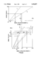
- FIG. 2 This property of the brake effects the braking system because the braking value (B) also follows different characteristic curves for brake actuation and brake release as functions of the brake application energy (Z). These curves are illustrated in FIG. 2 as corresponding characteristic curves (U) and (T).
- the difference in brake application energy (Z) between the characteristic curves (U and T) and the area between the characteristic curves (U, T) represent the hysteresis (Hy) and the hysteresis field, respectively, of the braking system.
- FIG. 2 is analogous to FIG. 1, in that the brake application energy values, ZA, ZR, ZOU and ZOT, determine the starting and end points of the characteristic curves (U, T).
- the braking system is, for example, actuated up to a point with the coordinates, such as at the desired braking value BS and the associated brake application energy ZS and if the brake application energy (Z) is decreased, then the difference in brake application energy ZS between the characteristic lines (U, T) assigned to the desired braking value BS, i.e., the hysteresis HyS, must be overcome before the braking system responds and decreases the braking value (B).
- the conventional process provides two alternatives.
- the known process decreases the brake application energy in steps until the hysteresis has been overcome and the deviation has disappeared.
- the known process decreases the brake application energy with a comparatively wide leap which leads to falling short of the desired braking value. Then the brake application energy is increased in steps until the desired braking value has again been reached.
- the known process may cause increased energy consumption. It is, therefore, an object of the present invention to provide a process which eliminates the problem of increased energy consumption.
- the present invention accomplishes this objective and others by providing a process for adjusting an actual braking value (B) to a desired braking value BS in a braking system having at least one brake (12, 13).
- the braking value (B) evolves as a function of the brake application energy (Z) for brake actuation and for brake release.
- the difference between the brake actuation function and the brake release function is the hysteresis (Hy) of the braking system for a given braking value (B).
- Brake application energy (Z) is fed to at least one brake.
- the braking value (B) is produced by the braking system as the brake application energy (Z) is fed to the brake (12, 13).
- the existing brake application energy ZS is decreased by a value (HyS+W) which comprises the hysteresis HyS associated with the desired braking value BS and an effect drop-off W, when the actual braking value BI deviates from the desired braking value BS in the direction of higher braking values (B) after a rise in the brake application energy (Z).
- a deviation (BI-BS) between said actual braking value (BI) and said desired braking value is recognized only when said deviation reaches at least predetermined limit value L. If a residual deviation (BIE1-BS) is present after decreasing the brake application energy, the brake application energy (Z) is further reduced in steps until the desired braking value BS is reached.
- a new hysteresis HyG is used in a subsequent braking process in which a deviation (BI-BS) of the original type occurs, if a residual deviation (BIE1-BS) is still present during a brake actuation in a braking process after the reduction of the existing brake application energy ZS.
- a utilization of correction value G is repeated in at least one further braking process in which a deviation (BI-BS) of the original type occurs until reduction through the using of the new hysteresis HyG results in the desired braking value BS.
- a new deviation (BS- BIE2) of the actual braking value BIE2 from the desired braking value BS in direction of lower braking values (B) is present during brake actuation in a braking process after reduction of the existing brake application energy ZS, by a correction value V
- a new hysteresis HyV is used in a subsequent braking process in which a deviation (BI-BS) of the original type occurs, wherein the new hysteresis HyV comprises a reduction of the hysteresis HyS associated with the desired braking value BS.
- the utilization of the correction value V is repeated in at least one further braking process in which a deviation (BI-BS) of the original type occurs until the desired braking value (BS) is obtained through utilization of the new hysteresis HyV.
- One embodiment of the braking system comprises at least one brake (12, 13), a braking value indicator (2) for emitting an electrical desired-braking value signal, a braking value sensor (1) for emitting an electrical actual braking value signal, an electrically controlled energy distributor (11) having a control system (14) and an output connected to said brake, and regulating electronics (4) having a first input connected to the braking value indicator (2) and a second input connected to the braking value sensor (1) and an output connected to the control system (14) of the energy distributor (11).
- the regulating electronics compare the actual braking value signal to the desired braking value signal to determine a brake application energy signal and transmit the brake application energy signal to the control system (14) of the energy distributor (11).
- the hysteresis (Hy) is stored as a function of the braking value (B).
- the regulating electronics reduce the brake application energy signal by a value resulting from reduction of existing brake application energy ZS by the value (HyS+W) when a deviation of the actual braking value BI from the desired braking value BS in direction of higher braking values (B) is detected following a rise in the brake application energy signal.
- the value (HyS+W) consists of the hysteresis HyS associated with the desired braking value BS and an effect drop-off W.
- the regulating electronics reduce the brake application energy signal in the subsequent braking process, in which a deviation (BI-BS) occurs, by a value corresponding to the application of a hysteresis HyG increased by a correction value G, if a residual deviation (BIE1-BS) still exists during a brake actuation in a braking process after the reduction of the brake application energy signal, and repeat the reduction in subsequent braking processes which follow a braking process in which a residual deviation has appeared until the desired braking value BS is attained.
- BI-BS deviation
- HyG hysteresis HyG
- G a correction value G
- the regulating electronics reduce the brake application energy signal by a value corresponding to the application of a hysteresis HyV reduced by a correction value V in the subsequent braking process in which a deviation (BI-BS) of the original type occurs when a deviation (BS-BIE2) of the actual braking value BIE2 from the desired braking value BS in direction of lower braking value (B) is present during a brake actuation in a braking process after the reduction of the brake application energy signal, and repeat the reduction in subsequent braking processes following a braking process in which such a deviation (BE-BIE2) has occurred until the desired braking value BS is obtained.
- BI-BS deviation of the original type occurs when a deviation (BS-BIE2) of the actual braking value BIE2 from the desired braking value BS in direction of lower braking value (B) is present during a brake actuation in a braking process after the reduction of the brake application energy signal, and repeat the reduction in subsequent braking processes following a braking process in which such
- the present invention is not only suitable for any type of brake application energy, but also for all technical fields in which the above-mentioned problems, as well as others, occur.
- An important area for application of the invention is the field of braking systems in the automotive industry.
- the pressure of a hydraulic and/or pneumatic pressure fluid is used as the brake application energy and compressed air is generally used as the pneumatic pressure fluid.
- FIG. 1 is a schematic diagram of the energy and braking value of a brake
- FIG. 2 is a schematic diagram of the energy and force of a braking system
- FIG. 3 schematically illustrates a braking system wherein solid lines represent energy lines and dot-dash lines represent signal lines.
- the electrically controlled braking system (“EBS") shown in FIG. 3 is provided in its basic design with a brake (12, 13) actuated by the supply of brake application energy (Z) from an energy supply (10).
- the brake (12,13) normally consists of a braking apparatus (12), which produces the brake force, and a brake application device (13), which receives the brake application energy (Z) and transforms it into a brake application force for the braking apparatus (12).
- the appertaining transmission elements for the energy are not designated in detail.
- an electrically controlled energy distributor (11) is associated with the brake (12, 13).
- the energy distributor (11) is connected to the energy supply (10), to the brake application device (13) and also to an energy relieving device, which is not shown. If a hydraulic or non-air pressure fluid is used, the energy relieving device is a collecting container which is normally subjected to atmospheric pressure. When compressed air is used, the energy-pressure relieving device is, as a rule, the atmosphere.
- the electric control system (14) of the energy distributor (11) requires a fixed brake application energy build-up signal, a brake application energy maintenance signal and an energy drop signal, which signals have fixed values.
- the energy distributor (11) connects the energy supply (10) to the brake application device (13).
- the control system (14)receives the brake application energy maintenance signal the energy distributor (11) disconnects the brake application device (13) from the energy-pressure relieving device and from the energy supply (10).
- the brake application energy reduction signal is received, the energy distributor (11) disconnects the brake application device (13) from the energy supply (10) and connects it to the energy relieving device.
- the electrical control system (14) of the energy distributor (11) requires a variable brake application energy signal.
- the energy distributor (11) connects the brake application device (13) either to the energy supply (10) or to the energy relieving device until the brake application energy (Z), which corresponds to the brake application energy signal, has been built up in the brake application device (13).
- this type of design is generally designated as a "proportional design”.
- the pressure of a pressure fluid e.g. compressed air
- the energy distributors used in either of the two designs are generally solenoid valves.
- the braking system is furthermore provided with an electrical braking value indicator (2), regulating electronics (4) and a braking value sensor (1). If one or several of the parameters, which are included in the braking value (B) according to the formula (I), are variable, then one or more additional sensors, which ascertain said parameters directly or indirectly, are included in the braking system. Such additional sensors are represented by 5 in FIG. 3.
- the braking value indicator (2) is capable of receiving a desired braking value demand issued by the operator in the form of a regulating element force and/or a regulating element travel by means of a regulating element (3) and of emitting a desired braking value signal corresponding to the braking value demand.
- the regulating element (3) is shown in the drawing as a pedal or hand lever.
- the braking value sensor (1) measures the existing actual braking value BI and issues a corresponding actual braking value signal. Additional sensors, such as sensor (5), act in a comparable manner with respect to the parameter ascertained by each sensor.
- the braking value indicator (2), the braking value sensor (1) and, if applicable, the sensor (5), are connected to inputs of the regulating electronics (4).
- the control system (14) of the energy distributor (11) is connected in the digital type of design to at least two outputs of the regulating electronics (4) and in the proportional type of design to one output of the regulating electronics (4).
- the regulating electronics (4) can be grouped together structurally. They can also be grouped, in the customary manner, with other electronic component groups, such as anti-blocking protection electronics.
- the operator actuates the braking system by acting upon the braking value indicator (2) by means of the regulating element (3), thereby, producing the desired braking value signal.
- the regulating electronics (4) are switched on upon receiving the produced desired braking value signal in this manner and are switched off when the desired braking value signal is terminated.
- the regulating electronics (4) query the desired braking value signal with their cycle frequency and compare the detected desired braking value signal to the one detected during the previous cycle.
- the regulating electronics (4) are always informed as to whether the desired braking value signal rises, remains unchanged or drops.
- the brake application energy follows the desired braking value signal.
- the information obtained by the course of the desired braking value signal provides the information as to whether brake actuation or brake release is taking place at that moment.
- the regulating electronics (4) can be designed so that they compare the brake application energy signal described below from cycle to cycle and obtain information on brake actuation or brake release from the course of this signal.
- the regulating electronics (4) calculate a brake application energy signal on the basis of the formula (I).
- the brake application energy signal corresponds to the brake application energy ZS for the desired braking value BS.
- the regulating electronics (4) transmit the brake application energy signal to the energy distributor (11).
- the energy distributor (11) then connects the brake application device (13) to the energy supply (10) until the brake application energy ZS corresponding to the desired braking value BS has built up in the brake application device (13).
- the energy distributor (11) connects the brake application device (13) to the energy relieving device until the corresponding drop of brake application energy has occurred in the brake application device (13).
- the regulating electronics (4) also query the braking value sensor (1) at each cycle and compare its actual braking value signal to the desired braking value signal.
- the regulating electronics can ascertain during a brake actuation, i.e., after the rise of the desired braking value signal or during unchanged desired braking value signal following its rise, whether the actual braking value signal deviates from the desired braking value signal. If such a deviation (BI-BS), of the actual braking value BI from the desired braking value BS in the direction of higher braking values (B), is detected, then the actual braking value BI is too high.
- the regulating electronics (4) then calculate the hysteresis HyS which is associated with the desired braking value BS based on formula (II) and decreases the brake application energy signal by a value which corresponds to a decrease in the existing brake application energy ZS by a value (HyS+W), which results from the above-mentioned hysteresis HyS and a value to be designated as an effect drop-off W.
- the effect drop-off W may have a fixed value or may depend on the magnitude of the existing deviation (BI-BS) of the actual braking value BI from the desired braking value BS. Furthermore, it may depend on the hysteresis HyS associated with the desired braking value BS. If the effect drop-off W has fixed value, the regulating electronics (4) can read it from a memory.
- BI-BS existing deviation
- This reduction of the brake application energy signal results in a drop of the brake force produced by the brake (12, 13) to a value assigned to the characteristic line (Y) for brake release in FIG. 1 according to the effect drop-off W and thereby results, as a rule, in the disappearance of the deviation (BI-BS).
- the regulating electronics (4) can calculate the hysteresis HyS directly after calculating the brake application energy signal and can buffer-store the calculated hysteresis until the possible occurrence of an excessive actual braking value BI.
- the regulating electronics (4) may be designed so that while they are switched on, i.e., during the current braking process, they continue to reduce the brake application energy signal as required in one step or in several steps until the disappearance of even the residual deviation (BIE1-BS).
- the individual step may have a fixed stored value which must be less than the effect drop-off W.
- the regulating electronics (4) may also be designed so that they calculate the magnitude of the step according to the formula:
- a braking system which reacts, as described above, each time the actual braking value becomes too great may be sensed in practice, by the operator as functioning unevenly and, therefore, uncomfortably.
- the braking system may be further designed so that the regulating electronics (4) only recognize the presence of a deviation (BI-BS) if it reaches a predetermined threshold value L.
- This threshold value L may have a constant magnitude over the entire possible brake application energy range.
- the magnitude is stored in the regulating electronics (4).
- the magnitude of the threshold value L may also depend on the magnitude of the desired braking value BS. In such a case, the regulating electronics (4) calculate the threshold value L simultaneously with the brake application energy signal.
- the regulating electronics (4) additionally calculate the magnitude of the threshold value L for each braking value (B) according to the following formula:
- LF is a threshold value factor and LO a beginning threshold value.
- the threshold value factor LF may be between 0.002 and 0.1.
- the beginning threshold value LO ensures that a defined threshold value also exists within the range of lower, braking values and that a "fluttering" operation of the braking system is avoided within this range.
- the beginning threshold value LO may be, for example:
- the line (R) is drawn so that the applicable threshold value L appears out-of-scale and large.
- the regulating electronics (4) carry out the reduction of the brake application energy signal by the value corresponding to the above-mentioned decrease (HyS+W) of the existing brake application energy ZS only when the deviation (BI-BS) in question reaches the magnitude of the current threshold value L.
- the regulating electronics (4) may also be designed so that the threshold value L is not applied within the range of high braking values (B) because within this full-braking range the greatest possible braking action is wanted, while even and comfortable performance of the braking system is of secondary importance.
- ZA, ZR and ZOT are determined in tests conducted with one or several actual brakes.
- the actual hysteresis which occurs in operation may deviate for various reasons from the hysteresis calculated according to the formula (II).
- the calculated hysteresis shall be called "theoretic" hereinafter.
- Such deviations may be caused by changes due to operation, maintenance or age of the braking system, in particular of the brake.
- the deviations may also be caused by unavoidable quality scattering occurring in the assembly-line production of the components of the braking system, in particular of the brake (12, 13).
- thermic condition of the brake (12, 13) is to be particularly noted.
- the curve (N) represents a case in which the actual hysteresis is greater than the theoretic hysteresis.
- the characteristic curve (T) for the release of the brake has changed to curve (N).
- the curve (O) represents a case in which the actual hysteresis is less than the theoretic hysteresis.
- the characteristic curve (T) for brake release has changed to the curve (O).
- the real hysteresis is greater than the theoretic hysteresis, such as (N)
- the reduction of the brake application energy ZS associated with the desired braking value BS by a value (HyS+W) results in the residual deviation (BIE1-BS), as discussed earlier.
- the new braking value BIE1 may be equal to the original actual braking value BI and the residual deviation (BIE1-BS) may be equal to the original deviation (BI-BS).
- the actual braking value BIE2 occurring after a reduction of the existing brake application energy value ZS by a value (HyS+W) drops below the desired braking value BS.
- the actual braking value BIE2 deviates from the desired braking value in the direction of lower braking values (B), so that a new deviation (BS-BIE2) exists after a reduction of the brake application energy ZS by the value (HyS+W).
- the regulating electronics (4) may be further developed in such a manner that they adapt the braking system to the applicable actual hysteresis.
- the regulating electronics (4) may be designed for the case of greater actual than theoretical hysteresis in such a manner that during their period of operation, i.e., during the current braking process, the regulating electronics will further reduce the brake application energy signal in one or more steps until the deviation (BI-BS) disappears.
- the regulating electronics (4) operate as in the previously described case where the deviation (BIE1-BS) is a residual deviation.
- the individual steps may be of a magnitude equal to, or greater than the effect drop-off W.
- the regulating electronics (4) may be designed so that they increase the brake application energy again in one or more steps until the deviation (BS-BIE2) disappears while they are switched on, i.e., during the current braking process.
- the individual steps may be of a magnitude equal to or greater than the effect drop-off W.
- the regulating electronics (4) may size the first step in accordance with the hysteresis assigned to the new actual braking value BIE2.
- the regulating electronics (4) may also be developed further so as to adapt the braking system in anticipation of the applicable actual hysteresis for subsequent braking processes on the basis of experience gathered during previous braking processes.
- the regulating electronics (4) in this further development, ascertain during a braking process, that after a reduction of the originally present brake application energy ZS, a residual deviation (BIE1-BS) is present (actual hysteresis is greater than theoretic hysteresis), the hysteresis HyS calculated on the basis of formula (II) will be enlarged by a correction value G. The obtained new hysteresis HyG is stored. If a deviation (BI-BS) of the original type then occurs in a subsequent braking process following a rise of brake application energy (Z), then the regulating electronics (4) calculate the value by which the existing brake application energy ZS must be decreased on the basis of the stored new hysteresis HyG.
- a deviation (BI-BS) of the original type then occurs in a subsequent braking process following a rise of brake application energy (Z)
- the regulating electronics (4) calculate the value by which the existing brake application energy ZS must be decreased on the basis of the stored new
- the brake application energy signal is then sized accordingly.
- the regulating electronics (4) can also be further developed so that, if a residual deviation (BIE1-BS) still exists in the braking process after the reduction of the brake application energy ZS by the value (HyG+W), the regulating electronics (4) will repeat the calculation, the storage and the application of the correction value G as above in this braking process for or during, respectively, one subsequent braking process and, if necessary, for or during, respectively, subsequent braking processes, in which a residual deviation (BIE1-BS) occurs. This repetition will occur until the deviation disappears and the applicable desired braking value BS is reached.
- the regulating electronics (4) If, after a reduction of the originally present brake application energy ZS by the value (HyS+W), the regulating electronics (4), as further for anticipatory adaptation of the braking system to the applicable actual hysteresis, ascertain in a braking process that the actual braking value BIE2 drops below the desired braking value BS (actual hysteresis smaller than theoretic hysteresis), then the regulating electronics (4) will decrease the hysteresis HyS calculated on the basis of formula (II) by a correction value V and store the new hysteresis HyV thus obtained.
- BS-BIE2 a new deviation
- a deviation (BI-BS) of the original type occurs in a subsequent braking process after a rise of the brake application energy (Z)
- the regulating electronics (4) will calculate the value by which the existing brake application energy ZS must be decreased on the basis of the stored new hysteresis HyV.
- the calculated value is equal to (HyV+W).
- the brake application energy signal is sized accordingly.
- the regulating electronics (4) can also be developed further so that they repeat the calculation, the storage and the application of the correction value V according to the above for and during, respectively, one subsequent braking process and, if necessary, for and during, respectively, subsequent braking processes, in which a deviation (BS-BIE2) of the new type occurs, until the deviation disappears. Therefore, the repetition continues until the applicable desired braking value BS is obtained. This repetition takes place if a deviation (BS-BIE2) occurs again after the reduction of the brake application energy ZS by the value (HyV+W).
- the correction values G and V may be addition values or multipliers. Their magnitude depends on the deviations of the practically occurring actual hysteresis from the theoretic hysteresis. If the correction value V is a multiplier, it is advantageously formed from the ratio between the actual braking value BIE2 and the desired braking value BS, as follows:
- the correction value G is a multiplier, it is advantageously formed from the ratio of the actual braking value BIE1 and the desired braking value BS, as follows:
- the actual braking value BIE1 is obtained by reducing the existing brake application energy ZS by the value (HyS+W).
- the magnitude of these correction values will be such that they will result in an increase or a decrease of up to 60% of the hysteresis HyS.
- the braking value (B) In actual braking systems, the braking value (B) normally follows a change in the brake application energy signal with a time delay. The time delay is due to unavoidable response delays and the time required for a change in the brake application energy. It is, therefore, advisable to design the regulating electronics (4) so that they carry out the described, step-by-step adaptation of the brake application energy signal, in the current braking process and the formation of the new hysteresis (HyG) or (HyV), respectively, only when the reaction of the braking system to the change of the brake application energy (Z) is completed. Such a change is completed, when the regulating electronics (4) no longer detect any change in the braking value (B) after a change in the brake application energy signal from one cycle to the next cycle.
- the regulating electronics (4) form the brake application energy signal internally, compare it with the signal of a sensor which ascertains the brake application energy and, depending on the result of the comparison, transmit either the brake application energy build-up signal, the brake application energy maintenance signal or the energy drop signal instead of the above-mentioned variable brake application energy signal to the control system (14) of the energy distributor (11).
- the brake (12, 13) in FIG. 3 may represent several brakes. It is also customary to assign energy supplies and energy distributors to each brake, for example, the additionally shown brake (6,7) has an energy supply (9) and an energy distributor (8).
- the brake (6,7) can represent several brakes. It is customary to designate the brakes supplied from one and the same energy supply and their energy distributors with the collective term braking circuit. In automotive engineering it is, for example, customary to assign a braking circuit either to each vehicle axle or to distribute the braking circuit over several vehicle axles, in which case the term diagonal distribution is used.
- the regulating electronics (4) may be divided into channels in which they process the formulas (I) to (VIII) in different manners and carry out the reduction of the brake application energy signal in adaptation to actual hysteresis in different manners. This makes it possible, for example, to coordinate the calculation of the brake application energy signal assigned to each energy distributor with the particular characteristics of the brake or brakes assigned to that energy distributor. This design is, for example, useful when different brakes, e.g. with different brake application devices or different braking apparatuses, are used. In this case, the number of channels of the regulating electronics (4) is advantageously adapted to the number of existing energy distributors.
- the last-mentioned further development of the regulating electronics (4) having channel divisions also makes it possible to weigh the variable parameters which may enter into the calculation of the brake application energy (ZS) differently, e.g. the variable ascertained by the sensor (5). In this manner, it is possible to vary the braking force distribution among the brakes and, thereby, vary the share in braking value production for each brake. This possibility is of importance in automotive engineering for example in order to obtain the same adhesion utilization between the wheel and the road on all of the wheels.
- ZS brake application energy
- the braking circuit are assigned to the axles for example, it is possible to consider the coefficient (F), which designates the weight, as being fixed in the channels assigned to one braking circuit as explained above, and as being variable in the channels assigned to one or several other braking circuits depending on the signals of the sensor (5).
- F the coefficient which designates the weight
Landscapes
- Engineering & Computer Science (AREA)
- Transportation (AREA)
- Mechanical Engineering (AREA)
- Braking Systems And Boosters (AREA)
- Regulating Braking Force (AREA)
Applications Claiming Priority (2)
| Application Number | Priority Date | Filing Date | Title |
|---|---|---|---|
| DE4317846A DE4317846A1 (de) | 1993-05-28 | 1993-05-28 | Verfahren zur Einstellung eines Bremswertes auf einen Soll-Bremswert |
| DE4317846.4 | 1993-05-28 |
Publications (1)
| Publication Number | Publication Date |
|---|---|
| US5496097A true US5496097A (en) | 1996-03-05 |
Family
ID=6489170
Family Applications (1)
| Application Number | Title | Priority Date | Filing Date |
|---|---|---|---|
| US08/245,427 Expired - Lifetime US5496097A (en) | 1993-05-28 | 1994-05-18 | Process for the adjustment of a braking value to a desired braking value |
Country Status (4)
| Country | Link |
|---|---|
| US (1) | US5496097A (fr) |
| EP (1) | EP0626297B1 (fr) |
| JP (1) | JP3876425B2 (fr) |
| DE (2) | DE4317846A1 (fr) |
Cited By (11)
| Publication number | Priority date | Publication date | Assignee | Title |
|---|---|---|---|---|
| US5660448A (en) * | 1994-11-11 | 1997-08-26 | Mercedes-Benz Ag | Method for controlling the braking process in a motor vehicle |
| US5669678A (en) * | 1995-05-13 | 1997-09-23 | Robert Bosch Gmbh | Process and apparatus for determining the application pressures and characteristic brake values of a vehicle |
| US5806938A (en) * | 1996-04-20 | 1998-09-15 | Robert Bosch Gmbh | Method and apparatus for determining a characteristic value of a wheel brake |
| WO1999016650A1 (fr) * | 1997-09-29 | 1999-04-08 | Continental Teves Ag & Co. Ohg | Procede pour appliquer des forces d'actionnement definies |
| US6457785B1 (en) * | 1995-12-26 | 2002-10-01 | Denso Corporation | Brake control apparatus for vehicle |
| US6648427B1 (en) * | 1998-07-31 | 2003-11-18 | Robert Bosch Gmbh | Method and device for controlling a brake system |
| US9061671B2 (en) * | 2013-08-27 | 2015-06-23 | Bendix Commercial Vehicle Systems Llc | Driver braking demand indicator apparatus for a heavy vehicle |
| US9797462B2 (en) | 2013-05-17 | 2017-10-24 | Ntn Corporation | Electric linear motion actuator and electric brake system |
| US9914438B2 (en) | 2013-09-24 | 2018-03-13 | Ntn Corporation | Vehicle braking force controller |
| US10293801B2 (en) * | 2015-12-22 | 2019-05-21 | Wabco Gmbh | Method for the adaptive control of a driver operation-dependent actual vehicle deceleration |
| US20220348177A1 (en) * | 2018-07-24 | 2022-11-03 | Robert Bosch Gmbh | Method for operating a brake system, and brake system |
Families Citing this family (7)
| Publication number | Priority date | Publication date | Assignee | Title |
|---|---|---|---|---|
| DE19805091C2 (de) * | 1998-02-09 | 2002-10-17 | Siemens Ag | Verfahren zum Ermitteln der Verzögerung eines Kraftfahrzeuges und Bremsanlage, die dieses Verfahren verwendet |
| DE10261547A1 (de) * | 2002-12-23 | 2004-07-08 | Wabco Gmbh & Co. Ohg | Verfahren zur Zuspannenergieregelung einer Fahrzeugkombination |
| JP4650282B2 (ja) * | 2006-01-20 | 2011-03-16 | 日産自動車株式会社 | 車両用ブレーキ装置 |
| JP5064071B2 (ja) * | 2007-03-22 | 2012-10-31 | Udトラックス株式会社 | 電子制御エアブレーキ装置 |
| JP4567021B2 (ja) * | 2007-04-06 | 2010-10-20 | Udトラックス株式会社 | Ebsのブレーキバルブ踏力検出構造 |
| DE102015115850A1 (de) | 2015-09-21 | 2017-03-23 | Knorr-Bremse Systeme für Nutzfahrzeuge GmbH | Verfahren zum Abbremsen eines Nutzfahrzeugs |
| AT522040B1 (de) * | 2018-12-17 | 2020-11-15 | Greenbrakes Gmbh | Elektromechanische Bremsenanlage |
Citations (10)
| Publication number | Priority date | Publication date | Assignee | Title |
|---|---|---|---|---|
| DE1961039A1 (de) * | 1969-12-05 | 1971-06-16 | Bosch Gmbh Robert | Fahrzeugbremsanlage mit Blockierschutz |
| US3888550A (en) * | 1973-02-05 | 1975-06-10 | Westinghouse Bremsen Apparate | Anti-wheel skid control system providing controlled reapplication of brake pressure |
| US4043608A (en) * | 1971-08-13 | 1977-08-23 | Daimler-Benz Aktiengesellschaft | Brake force control device for back-control |
| US4225195A (en) * | 1978-05-26 | 1980-09-30 | Wabco Westinghouse Gmbh | Process and device for the regulation of braking pressure in lock-up protection systems |
| DE3237921A1 (de) * | 1982-10-13 | 1984-04-19 | Robert Bosch Gmbh, 7000 Stuttgart | Steuereinrichtung |
| DE3502825A1 (de) * | 1985-01-29 | 1986-07-31 | Wabco Westinghouse Fahrzeugbremsen GmbH, 3000 Hannover | Ueberlast-schutz- und/oder -warneinrichtung |
| US4859002A (en) * | 1987-07-09 | 1989-08-22 | Sumitomo Electric Industries, Ltd. | Antiskid brake control device |
| US4875740A (en) * | 1986-02-20 | 1989-10-24 | Tokico, Ltd. | Braking device for use in a motor vehicle |
| US5082333A (en) * | 1989-05-23 | 1992-01-21 | Nippondenso Co., Ltd. | Anti-skid control system for use in motor vehicle |
| US5364173A (en) * | 1991-01-09 | 1994-11-15 | Honda Giken Kogyo Kabushiki Kaisha | Pressure source for pressure device |
Family Cites Families (3)
| Publication number | Priority date | Publication date | Assignee | Title |
|---|---|---|---|---|
| JPS59114152A (ja) * | 1982-12-20 | 1984-07-02 | Nippon Air Brake Co Ltd | ブレ−キ制御方法 |
| DE3603810A1 (de) * | 1986-02-07 | 1987-08-13 | Bosch Gmbh Robert | Regeleinrichtung |
| DE4007360A1 (de) * | 1990-03-08 | 1991-09-12 | Daimler Benz Ag | Verfahren zur bremsdruckverteilung auf die achsen eines kraftfahrzeugs mit abs-druckmittelbremse |
-
1993
- 1993-05-28 DE DE4317846A patent/DE4317846A1/de not_active Withdrawn
-
1994
- 1994-03-25 DE DE59400447T patent/DE59400447D1/de not_active Expired - Lifetime
- 1994-03-25 EP EP94104779A patent/EP0626297B1/fr not_active Expired - Lifetime
- 1994-05-12 JP JP13351794A patent/JP3876425B2/ja not_active Expired - Lifetime
- 1994-05-18 US US08/245,427 patent/US5496097A/en not_active Expired - Lifetime
Patent Citations (10)
| Publication number | Priority date | Publication date | Assignee | Title |
|---|---|---|---|---|
| DE1961039A1 (de) * | 1969-12-05 | 1971-06-16 | Bosch Gmbh Robert | Fahrzeugbremsanlage mit Blockierschutz |
| US4043608A (en) * | 1971-08-13 | 1977-08-23 | Daimler-Benz Aktiengesellschaft | Brake force control device for back-control |
| US3888550A (en) * | 1973-02-05 | 1975-06-10 | Westinghouse Bremsen Apparate | Anti-wheel skid control system providing controlled reapplication of brake pressure |
| US4225195A (en) * | 1978-05-26 | 1980-09-30 | Wabco Westinghouse Gmbh | Process and device for the regulation of braking pressure in lock-up protection systems |
| DE3237921A1 (de) * | 1982-10-13 | 1984-04-19 | Robert Bosch Gmbh, 7000 Stuttgart | Steuereinrichtung |
| DE3502825A1 (de) * | 1985-01-29 | 1986-07-31 | Wabco Westinghouse Fahrzeugbremsen GmbH, 3000 Hannover | Ueberlast-schutz- und/oder -warneinrichtung |
| US4875740A (en) * | 1986-02-20 | 1989-10-24 | Tokico, Ltd. | Braking device for use in a motor vehicle |
| US4859002A (en) * | 1987-07-09 | 1989-08-22 | Sumitomo Electric Industries, Ltd. | Antiskid brake control device |
| US5082333A (en) * | 1989-05-23 | 1992-01-21 | Nippondenso Co., Ltd. | Anti-skid control system for use in motor vehicle |
| US5364173A (en) * | 1991-01-09 | 1994-11-15 | Honda Giken Kogyo Kabushiki Kaisha | Pressure source for pressure device |
Non-Patent Citations (2)
| Title |
|---|
| Article By: Fritsche, Gunter & Reinecke, Erich entitled "Elektronishes Bremsregelsystem fur Nutzfahrzeuge", in ATZ Automobiltechnische Zeitschrift 74, 1972, 7 S.277-282; insb. Abschn. 4.2. |
| Article By: Fritsche, Gunter & Reinecke, Erich entitled Elektronishes Bremsregelsystem fur Nutzfahrzeuge , in ATZ Automobiltechnische Zeitschrift 74, 1972, 7 S.277 282; insb. Abschn. 4.2. * |
Cited By (15)
| Publication number | Priority date | Publication date | Assignee | Title |
|---|---|---|---|---|
| US5660448A (en) * | 1994-11-11 | 1997-08-26 | Mercedes-Benz Ag | Method for controlling the braking process in a motor vehicle |
| US5669678A (en) * | 1995-05-13 | 1997-09-23 | Robert Bosch Gmbh | Process and apparatus for determining the application pressures and characteristic brake values of a vehicle |
| US6457785B1 (en) * | 1995-12-26 | 2002-10-01 | Denso Corporation | Brake control apparatus for vehicle |
| US5806938A (en) * | 1996-04-20 | 1998-09-15 | Robert Bosch Gmbh | Method and apparatus for determining a characteristic value of a wheel brake |
| WO1999016650A1 (fr) * | 1997-09-29 | 1999-04-08 | Continental Teves Ag & Co. Ohg | Procede pour appliquer des forces d'actionnement definies |
| US6435625B1 (en) | 1997-09-29 | 2002-08-20 | Continental Teves Ag & Co., Ohg | Method for applying defined operating forces |
| US6648427B1 (en) * | 1998-07-31 | 2003-11-18 | Robert Bosch Gmbh | Method and device for controlling a brake system |
| US9797462B2 (en) | 2013-05-17 | 2017-10-24 | Ntn Corporation | Electric linear motion actuator and electric brake system |
| US9061671B2 (en) * | 2013-08-27 | 2015-06-23 | Bendix Commercial Vehicle Systems Llc | Driver braking demand indicator apparatus for a heavy vehicle |
| CN105473394A (zh) * | 2013-08-27 | 2016-04-06 | 奔迪士商业运输系统公司 | 用于重型车辆的驾驶员制动需求指标设备 |
| CN105473394B (zh) * | 2013-08-27 | 2017-12-22 | 奔迪士商业运输系统公司 | 用于重型车辆的驾驶员制动需求指标设备 |
| US9914438B2 (en) | 2013-09-24 | 2018-03-13 | Ntn Corporation | Vehicle braking force controller |
| US10293801B2 (en) * | 2015-12-22 | 2019-05-21 | Wabco Gmbh | Method for the adaptive control of a driver operation-dependent actual vehicle deceleration |
| US20220348177A1 (en) * | 2018-07-24 | 2022-11-03 | Robert Bosch Gmbh | Method for operating a brake system, and brake system |
| US11958453B2 (en) * | 2018-07-24 | 2024-04-16 | Robert Bosch Gmbh | Method for operating a brake system, and brake system |
Also Published As
| Publication number | Publication date |
|---|---|
| EP0626297A1 (fr) | 1994-11-30 |
| EP0626297B1 (fr) | 1996-07-24 |
| JP3876425B2 (ja) | 2007-01-31 |
| DE4317846A1 (de) | 1994-12-01 |
| JPH06344875A (ja) | 1994-12-20 |
| DE59400447D1 (de) | 1996-08-29 |
Similar Documents
| Publication | Publication Date | Title |
|---|---|---|
| US5496097A (en) | Process for the adjustment of a braking value to a desired braking value | |
| US6099085A (en) | Method and apparatus for a deceleration-regulated braking system | |
| US5505526A (en) | Adjusting actual brake pressure to match stored pressure values associated with a brake pedal position | |
| EP0205277B1 (fr) | Système de freinage de véhicule | |
| KR900003948B1 (ko) | 폐쇄루우프형 차량감속도제어장치 | |
| US5050938A (en) | Trailer braking in electronically controlled braking systems | |
| EP0246790A2 (fr) | Système de freinage de véhicule | |
| DE4438148B4 (de) | Bremssteuereinrichtung für Kraftfahrzeuge | |
| US5782541A (en) | Pressure control process and apparatus | |
| US5344222A (en) | Method for controlling a braking operation including determining brake coefficient forces | |
| US5511863A (en) | Hybrid brake control system | |
| JPS6171261A (ja) | 制動力制御装置 | |
| JPH0523981B2 (fr) | ||
| US5088042A (en) | Electronic braking system | |
| DE19501286B4 (de) | Verfahren und Vorrichtung zur Steuerung einer Bremsanlage eines Fahrzeugs | |
| US6314358B1 (en) | Brake control for vehicles, especially for rail vehicles and a method for controlling vehicle brakes | |
| US6719376B1 (en) | Process for actuating first and second brakes of a vehicle simultaneously | |
| EP1765650A2 (fr) | Procede de commande de freinage de vehicule utilisant une repartition dynamique de la force basee sur des charges par roue | |
| US3537758A (en) | Device for controlling the pneumatic braking force of a railway train | |
| JP5214835B2 (ja) | ブレーキ装置の制御方法および装置 | |
| US6234583B1 (en) | Process for regulating a predetermined, changeable brake pressure in the wheel brakes of a braking system | |
| US6196640B1 (en) | Method for coordinating braking forces between connected units of a vehicle train | |
| US5419621A (en) | Braking system | |
| US4080007A (en) | Brake-force controller for vehicles | |
| JPS60240555A (ja) | 車両ブレーキ装置の圧力調整器を使用する方法及び車両ブレーキ装置 |
Legal Events
| Date | Code | Title | Description |
|---|---|---|---|
| AS | Assignment |
Owner name: WABCO VERMOGENSVERWALTUNGS GMBH, GERMANY Free format text: ASSIGNMENT OF ASSIGNORS INTEREST;ASSIGNOR:ECKERT, HORST;REEL/FRAME:007008/0653 Effective date: 19940510 |
|
| STCF | Information on status: patent grant |
Free format text: PATENTED CASE |
|
| FEPP | Fee payment procedure |
Free format text: PAYOR NUMBER ASSIGNED (ORIGINAL EVENT CODE: ASPN); ENTITY STATUS OF PATENT OWNER: LARGE ENTITY |
|
| FPAY | Fee payment |
Year of fee payment: 4 |
|
| FPAY | Fee payment |
Year of fee payment: 8 |
|
| SULP | Surcharge for late payment |
Year of fee payment: 7 |
|
| FPAY | Fee payment |
Year of fee payment: 12 |
|
| REMI | Maintenance fee reminder mailed |