US5488324A - Detection circuit for detecting a state of a control system with improved accuracy - Google Patents
Detection circuit for detecting a state of a control system with improved accuracy Download PDFInfo
- Publication number
- US5488324A US5488324A US08/300,939 US30093994A US5488324A US 5488324 A US5488324 A US 5488324A US 30093994 A US30093994 A US 30093994A US 5488324 A US5488324 A US 5488324A
- Authority
- US
- United States
- Prior art keywords
- voltage
- circuit
- voltage signal
- current
- supplied
- Prior art date
- Legal status (The legal status is an assumption and is not a legal conclusion. Google has not performed a legal analysis and makes no representation as to the accuracy of the status listed.)
- Expired - Lifetime
Links
Images


Classifications
-
- B—PERFORMING OPERATIONS; TRANSPORTING
- B60—VEHICLES IN GENERAL
- B60T—VEHICLE BRAKE CONTROL SYSTEMS OR PARTS THEREOF; BRAKE CONTROL SYSTEMS OR PARTS THEREOF, IN GENERAL; ARRANGEMENT OF BRAKING ELEMENTS ON VEHICLES IN GENERAL; PORTABLE DEVICES FOR PREVENTING UNWANTED MOVEMENT OF VEHICLES; VEHICLE MODIFICATIONS TO FACILITATE COOLING OF BRAKES
- B60T8/00—Arrangements for adjusting wheel-braking force to meet varying vehicular or ground-surface conditions, e.g. limiting or varying distribution of braking force
- B60T8/32—Arrangements for adjusting wheel-braking force to meet varying vehicular or ground-surface conditions, e.g. limiting or varying distribution of braking force responsive to a speed condition, e.g. acceleration or deceleration
- B60T8/88—Arrangements for adjusting wheel-braking force to meet varying vehicular or ground-surface conditions, e.g. limiting or varying distribution of braking force responsive to a speed condition, e.g. acceleration or deceleration with failure responsive means, i.e. means for detecting and indicating faulty operation of the speed responsive control means
- B60T8/885—Arrangements for adjusting wheel-braking force to meet varying vehicular or ground-surface conditions, e.g. limiting or varying distribution of braking force responsive to a speed condition, e.g. acceleration or deceleration with failure responsive means, i.e. means for detecting and indicating faulty operation of the speed responsive control means using electrical circuitry
-
- B—PERFORMING OPERATIONS; TRANSPORTING
- B62—LAND VEHICLES FOR TRAVELLING OTHERWISE THAN ON RAILS
- B62D—MOTOR VEHICLES; TRAILERS
- B62D5/00—Power-assisted or power-driven steering
- B62D5/06—Power-assisted or power-driven steering fluid, i.e. using a pressurised fluid for most or all the force required for steering a vehicle
- B62D5/30—Safety devices, e.g. alternate emergency power supply or transmission means to ensure steering upon failure of the primary steering means
-
- G—PHYSICS
- G05—CONTROLLING; REGULATING
- G05B—CONTROL OR REGULATING SYSTEMS IN GENERAL; FUNCTIONAL ELEMENTS OF SUCH SYSTEMS; MONITORING OR TESTING ARRANGEMENTS FOR SUCH SYSTEMS OR ELEMENTS
- G05B9/00—Safety arrangements
- G05B9/02—Safety arrangements electric
-
- B—PERFORMING OPERATIONS; TRANSPORTING
- B60—VEHICLES IN GENERAL
- B60G—VEHICLE SUSPENSION ARRANGEMENTS
- B60G2600/00—Indexing codes relating to particular elements, systems or processes used on suspension systems or suspension control systems
- B60G2600/08—Failure or malfunction detecting means
Definitions
- the present invention generally relates to control systems, and more particularly to a detection circuit used in a control system for detecting a state of an object that is under control.
- Microcomputers are used in various control systems for detecting the state of an object that is under control and for controlling the same based upon the information about the state thus detected.
- the driver circuits of actuation devices such as electric motors or magnetic relays, for example, the state of the actuation device is detected by a detection circuit, and the output of the detection circuit indicative of the state of the actuation device is sent to a microcomputer for subsequent control.
- the detection circuit is driven by a supply voltage that is different from the supply voltage that powers the actuation devices.
- actuation devices are powered by a supply voltage of 12 volts or 24 volts in the automotive applications, while the detection circuit is usually powered by a supply voltage of 5 volts. Thereby, there frequently occurs a case wherein the detection circuit has to detect a voltage that exceeds the detection circuit supply voltage.
- the detection circuit In order to guarantee a normal operation of the detection circuit, the detection circuit usually uses a voltage divider for reducing the voltage that is to be detected.
- the use of the voltage divider raises a problem of reduced sensitivity of the detection circuit, as the variation of the voltage to be detected is demagnified by the use of the voltage divider. Thereby, the detection circuit tends to be vulnerable to noises and the risk of an erroneous operation of the detection circuit increases.
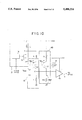
- FIG. 1 shows an example of a control system that controls an actuation device by a microcomputer.
- the actuation device includes a solenoid L powered by a supply voltage V DD at a power supply line and a drive circuit 1 A that drives the solenoid L via a MOS transistor Tr, which in turn is connected in series to the solenoid L between the power supply line and the ground.
- the solenoid L may be used for actuating a mechanical device such as a brake of an automobile.
- the solenoid L, the MOS transistor Tr, and the drive circuit 1 A form a system 1 that is subjected to control, and there is provided a microcomputer (MPV) 2 for controlling the system 1.
- MPV microcomputer
- the microcomputer 2 monitors the state of the system 1 such as the state of the solenoid L and controls the same in response to the monitored state of the system 1, based upon an external control signal supplied to the microcomputer 2.
- a detection circuit to be described below is used.
- FIG. 2 shows the construction of a most fundamental detection circuit 10 that is used in the system 1 of FIG. 1.
- the detection circuit 10 includes a comparator 3 B having an inverting input terminal connected to a node A, where the solenoid L and the transistor Tr are connected in series, and a non-inverting input terminal connected to a reference voltage source 3 A .
- the comparator 3 B is activated by a supply voltage V CC and produces an output voltage S when the voltage level at the node A has decreased below the reference voltage.
- This output voltage S is supplied to the microprocessor 2 of FIG. 1.
- the microprocessor 2 supplies a control voltage to a gate of the MOS transistor Tr that forms the drive circuit 1 A .
- the detection circuit 10 of FIG. 2 operates only when the supply voltage V DD is approximately equal to or lower than the supply voltage V CC .
- the voltage V DD exceeds the voltage V CC
- the comparator 3 B and hence the detection circuit 10 no longer operates properly.
- a detection circuit shown in FIG. 3 wherein the circuit includes a voltage divider 4 that in turn includes a first resistor R 11 and a second resistor R 12 that are connected in series. Thereby, the voltage at the node A is voltage-divided by the resistors R 11 and R 12 to a level that does not exceed the supply voltage V CC of the comparator 3 B . Thereby, the circuit of FIG. 3 can operate properly even when the voltage level of the supply voltage V DD exceeds the voltage level of the supply voltage V CC .
- the voltage divider 5 includes first and second resistors R 13 and R 14 that are connected in series between the voltage supply line carrying the supply voltage V DD and the ground.
- a reference voltage V REF is produced across the resistor R 14 by the voltage-dividing of the supply voltage V DD , and the comparator 3 B becomes immune to any voltage variation in the supply voltage V DD .
- the operation of the comparator 3 B is held normal even when the supply voltage V DD exceeds the supply voltage V CC .
- the circuit is suitable for use in the car-borne or other vehicle-carried control systems.
- the variation of the voltage at the node A is demagnified as a result of the voltage-dividing. In other words, the extent of variation of the voltage at the node A is reduced when the voltage variation is detected by the comparator 3 B .
- the sensitivity of the comparator 3 B remains the same. Thereby, there occurs a problem in that the S/N ratio of the detection circuit is poor and the control system 1 is vulnerable to the noises that are superposed on the supply voltage V DD .
- the detection circuit should be able to detect any deviation of the voltage at the node A from a predetermined, designed level. This is particularly important when detecting the anomaly that may be caused by a leak of the current in the solenoid. When such an anomaly is overlooked, for example in the brake control system or other essential control systems of vehicles, a disastrous event may be caused.
- Another and more specific object of the present invention is to provide a detection circuit for use in a control system for detecting the state of an actuation device with an increased operational range and an improved accuracy.
- Another object of the present invention is to provide a detection circuit for detecting a state of an object circuit, comprising voltage-current conversion means supplied with a first voltage signal indicative of the state of said object circuit for producing an output current having a magnitude indicative of said state in response to said first voltage signal; detection means activated by a supply-voltage, said detection means being supplied with a second voltage signal for detecting said state of said object circuit in response thereto; clamping means having an input terminal to which said output current of said voltage-current conversion means is supplied, said clamping means clamping a voltage of said input terminal at a predetermined level, said clamping means producing said second voltage signal in response to said output current such that said second voltage has a magnitude proportional to said first voltage signal and such that said magnitude of said second voltage signal is smaller than said supply voltage, said clamping means supplying said second voltage signal to said detection means.
- the state of the actuation device which is driven by the first supply voltage, can be detected by the comparator that is driven by the second supply voltage that may be lower than the first supply voltage, without sacrificing the accuracy of detection.
- the detection circuit of the present invention does not use the voltage divider that inevitably causes a reduction in the accuracy of detection.
- the state of the control system is detected by a controller or a computer with improved accuracy and simultaneously with an improved reliability.
- the detection circuit of the present invention is suitable for use in the control systems the malfunctioning of which may cause a disastrous effect, such as the vehicle control systems.
- FIG. 1 is a circuit diagram showing the construction of a conventional control system that includes a solenoid and a microcomputer for controlling the solenoid via a drive circuit;
- FIG. 2 is a circuit diagram showing the construction of a conventional detection circuit applicable to the control system of FIG. 1 for monitoring the state of the solenoid;
- FIG. 3 is a circuit diagram showing the construction of another conventional detection circuit applicable to the control system of FIG. 1 for monitoring the state of the solenoid;
- FIG. 4 is a circuit diagram showing the construction of still another conventional detection circuit that is applicable to the control system of FIG. 1 for monitoring the state of the solenoid;
- FIG. 5(A) is a block diagram showing the principle of the present invention.
- FIG. 5(B) is a circuit diagram showing an essential part of the detection circuit of FIG. 5(A);
- FIGS. 6(A)-6(D) are diagrams for explaining the principle of operation of the detection circuit according to the first embodiment of the present invention.
- FIG. 7 is a circuit diagram showing the construction of the detection circuit according to a first embodiment of the present invention.
- FIG. 8 is a circuit diagram showing the construction of the detection circuit according to a second embodiment of the present invention.
- FIG. 9 is a circuit diagram showing the construction of the detection circuit according to a third embodiment of the present invention.
- FIG. 10 is a circuit diagram showing the construction of the detection circuit according to a fourth embodiment of the present invention.
- FIG. 11 is a circuit diagram showing the construction of the detection circuit according to a fifth embodiment of the present invention.
- FIG. 12 is a circuit diagram showing the construction of the detection circuit according to a sixth embodiment of the present invention.
- FIG. 13 is a circuit diagram showing the construction of the detection circuit according to a seventh embodiment of the present invention.
- FIG. 14 is a circuit diagram showing the construction of the detection circuit according to an eighth embodiment of the present invention.
- FIGS. 5(A) and 5(B) As well as FIGS. 6(A)-6(D).
- the system includes an actuation circuit 13 that in turn includes an actuation device 13a such as a solenoid and a driver circuit 13b that drives the actuation device 13a.
- the driver circuit 13b is supplied with a control signal from the microcomputer MPU and activates the solenoid 13a.
- the voltage level at a node A inside the circuit 13 changes.
- the voltage level of the node A represented as V A
- the actuation circuit 13 and hence the actuation device 13a is driven by a first supply voltage V DD .
- a resistor R To the node A, an end of a resistor R is connected such that a current I flows through the resistor R in response to the voltage V A .
- the resistor R has another end connected to a voltage clamp circuit 12 that clamps the voltage at a node B, which corresponds to the aforementioned another end, at a voltage level V B .
- the clamp circuit 12 produces an output voltage corresponding to the current I and supplies the same to a comparator 11 that is driven by a second supply voltage V CC .
- the comparator 11 compares the output voltage of the circuit 12 with a predetermined, reference voltage V REF and produces an output signal S indicative of the result of the comparison.
- the comparator 11 supplies the output signal S to the microcomputer MPU.
- FIG. 5(B) shows the construction of the clamp circuit 12.
- the clamp circuit 12 includes a bipolar transistor Q 1 having an emitter connected to the node B. Further, the transistor Q 1 has a base supplied with a predetermined bias voltage V Bias , and a collector that is connected to the ground via a resistor r. Thereby, a voltage V C appearing across the resistor r is supplied to the comparator 11 via an output terminal 11 a .
- the actuation circuit 13a comprises a solenoid L while the drive circuit 13b comprises a MOS transistor Tr that is connected in series to the solenoid L.
- the transistor Tr is supplied with a control signal at a gate thereof, and a current flows from the supply voltage line carrying the first supply voltage V DD to the ground upon the turning-on of the transistor Tr.
- the level of the voltage at the node A decreases, while when the transistor Tr is turned off, the node A assumes a high voltage level substantially equal to the supply voltage V DD .
- the transistor Tr is defective and a leak current flows through the transistor Tr, the voltage level of the node A deviates from the designed voltage level.
- the voltage V A at the node A is converted to the current I that flows through the resistor R, and the current I is supplied to the emitter of the transistor Q 1 that forms the clamp circuit 12.
- the voltage level V B at the node B corresponding to the emitter voltage of the transistor Q 1 , increases linearly with the voltage V A as shown in FIG. 6(B) as long as the transistor Tr is not turned on and the current I is zero.
- the current I that flows through the transistor Q 1 increases with increasing voltage V A as shown in FIG. 6(C).
- the voltage V C is substantially smaller than the voltage V A .
- the value of the resistor r at the collector of the transistor Q 1 it is possible to set the voltage V C below the supply voltage V CC that activates the comparator 11. It should be noted that the voltage V C is given as ##EQU1## where K is a constant and given as
- the input voltage V C does not exceed the supply voltage V CC of the comparator 11 when the parameter K is set appropriately, the normal operation of the comparator 11 is guaranteed. Further, the conversion of the voltage from the first voltage V A to the second voltage V C is achieved without using a voltage divider. In other words, there is no sacrifice in the accuracy of the voltage detection during the conversion of the voltage V A to the voltage V C .
- FIG. 7 shows a first embodiment of the present invention.
- the circuit 13 includes, in addition to the solenoid L and the MOS transistor Tr, a control circuit 1 A for controlling the transistor Tr in response to the output from a microcomputer 2.
- the circuit 1 A forms a part of the driver circuit 13b together with the MOS transistor Tr.
- the clamp circuit 12 has a construction substantially as described with reference to FIG. 6(A) and produces the output voltage V C at the collector of the transistor Q 1 .
- the output of the clamp circuit 12 is supplied to the comparator 11 that produces the output signal S in response to the result of comparison, and the comparator 11 supplies the output signal S to the microcomputer 2.
- the supply voltage V DD for driving the solenoid L may be set to 30 volts, while the supply voltage V CC for driving the comparator 11 is set to 5 volts. Further, the resistors R and r are set such that the voltage V B does not exceed the supply voltage V CC as already mentioned. Thereby, the comparator 11 operates without problem in spite of the use of the supply voltage V DD that substantially exceeds the supply voltage V CC . Thereby, the state of the actuation device, such as the solenoid L used for the motor, relay or actuator, can be monitored by the microcomputer 2 with an improved precision that is given by the coefficient r/R.
- FIG. 8 shows a second embodiment of the present invention.
- the detection circuit of the present invention has a construction substantially identical with the circuit of FIG. 7, except that the voltage V B at the node B is supplied directly to a comparator 21 that is driven by the second supply voltage V CC .
- the comparator 21 is supplied with a reference voltage V REF from a reference voltage source 24 A and produces an output signal S' in response to the result of the comparison.
- the output signal S' is supplied further to the microcomputer 2.
- FIG. 9 is a circuit diagram that combines the feature of the circuit of FIG. 7 and the feature of the circuit of FIG. 8.
- the circuit employs both the comparator 11 and the comparator 21 for detecting the voltage V C appearing at the node C and the voltage V B at the node B.
- the comparator 11 is supplied with the voltage V C and further with the reference voltage from the voltage source 14 A for producing an output signal S 2 in correspondence to the output signal S.
- the comparator 21 is supplied with the voltage V B and further with the reference voltage from the voltage source 24 A for producing an output signal S 1 in correspondence to the output signal S'. Both the output signals S 1 and S 2 are supplied to the microcomputer 2.
- the detection circuit of the present embodiment is operational for the entire range of the voltage V A .
- the detection circuit includes the driver circuit 13, the resistor R, the clamp circuit 12, and the comparator 11, similarly to the first embodiment, wherein there is provided a reference circuit 14 B that produces the reference voltage V REF based upon the supply voltage V DD .
- the reference circuit 14 B includes a bipolar transistor Q 2 having an emitter that is supplied with the supply voltage V DD via a resistor R 1 and a collector that is grounded via a resistor R 2 . Further, the transistor Q 2 has a base that is supplied with the bias voltage V Bias commonly with the transistor Q 1 . Thereby, the transistor Q 2 produces the reference voltage V REF across the resistor R 2 in response to the supply voltage V DD .
- the transistor Q 2 generally has a common emitter current gain that is substantially identical with the same common emitter current gain H FE of the transistor Q 1 . Even when there is a variation in the common emitter current gain between the transistor Q 1 and the transistor Q 2 , such a variation tends to be canceled out in the construction of FIG. 10, and the operation of the comparator 11 is stabilized.
- a constant current source 15 powered by the supply voltage V CC is provided for setting the threshold condition that is detected by the comparator 11.
- the threshold condition means the condition in which the both input voltages to the comparator 11 assume the same voltage level.
- the constant current source 15 is powered by the supply voltage V CC and supplies a constant current I T to the node C.
- the above equation indicates that the voltage level V A that is lower than the supply voltage V DD by I T ⁇ R becomes the threshold level that is detected by the comparator 11. It should be noted that the above equation does not contain the term of V REF . Thus, the threshold operation of the comparator 11 becomes immune to the variation of the supply voltage V DD even when the reference voltage V REF is produced from the supply voltage V DD . It should also be noted that the threshold level V A becomes equal to the supply voltage V DD when the constant current source 15 is omitted, assuming that the transistors Q 1 and Q 2 have the same common emitter current gain H FE .
- FIG. 11 shows a fifth embodiment of the present invention.
- FIG. 12 shows a sixth embodiment of the present invention.
- the circuit is a modification of the circuit of FIG. 11 and includes a current mirror 17 at the collector of the transistors Q 1 and Q 2 .
- the current mirror 17 includes a first transistor Q 3 and a second transistor Q 4 having respective bases connected with each other.
- the base and the collector of the transistor Q 3 are connected with each other, and, further, are connected to the collector of the transistor Q 1 , while the emitter of the transistor Q 3 is connected to the ground as usual in the current mirror circuit.
- the transistor Q 4 has a collector connected to the collector of the transistor Q 2 and an emitter connected to the ground.
- the current flowing through the transistor Q 4 becomes equal to the current flowing through the transistor Q 3 .
- the current flowing through the transistor Q 4 represents the current that flows through the resistor R, which in turn reflects the voltage level of the node A.
- the voltage level at the collector of the transistor Q 2 changes in response to the current flowing through the transistor Q 4 , and the circuit of FIG. 12 detects the state of the solenoid L by detecting the voltage level of the collector of the transistor Q 2 by an ordinary amplifier circuit 31 that includes a transistor Q 5 .
- the transistor Q 5 has a collector supplied with the second supply voltage V CC via a resistor R 3 and an emitter connected to the ground.
- FIG. 13 shows a seventh embodiment of the present invention, wherein the embodiment of FIG. 11 is applied for detecting the state of two, different solenoids L 1 and L 2 that form actuation circuits 13 A and 13 B respectively.
- Each of the circuits 13 A and 13 B has a construction identical with the circuit 13.
- a first resistor R 101 is provided in correspondence to the resistor R for converting a voltage appearing at a node A 1 in the circuit 13 A to a current
- a clamp circuit 22 A is provided in correspondence to the clamp circuit 12.
- the clamp circuit 22 A includes a transistor Q 11 corresponding to the transistor Q 1 and a resistor r 1 corresponding to the resistor r.
- a diode D 11 is provided between the resistor R 101 and the circuit 22 A in correspondence to the diode D 1 .
- a second resistor R 102 also in correspondence to the resistor R for converting a voltage appearing at a node A 2 of the circuit 13 B to a current
- a clamp circuit 22 B is provided in correspondence to the clamp circuit 12.
- the clamp circuit 22 B includes a transistor Q 12 corresponding to the transistor Q 1 and a resistor r 2 also corresponding to the resistor r. Further, a diode D 12 is provided between the resistor R 102 and the circuit 22 B in correspondence to the diode D 1 . As the operation of the circuits 22 A and 22 B is obvious from the description of the previous embodiments, further description will be omitted. Further, there are provided constant current sources 15a and 15b in correspondence to the constant current source 15. The output voltage produced by the clamp circuits 22 A and 22 B are supplied to comparators 21 A and 21 B respectively, wherein the respective comparators 21 A and 21 B are supplied with the reference voltage V REF from the reference circuit 14 B and produce output signals S 1 and S 2 respectively.
- FIG. 14 shows an eighth embodiment of the present invention for detecting the state of the respective solenoids in the actuation circuit 13 A and the actuation circuit 13 B .
- the circuit of FIG. 14 operates similarly to the circuit of FIG. 13.
- the parts that are identical with the circuit of FIG. 13 are designated by the same reference numerals.
Landscapes
- Engineering & Computer Science (AREA)
- Transportation (AREA)
- Mechanical Engineering (AREA)
- Physics & Mathematics (AREA)
- General Physics & Mathematics (AREA)
- Automation & Control Theory (AREA)
- Chemical & Material Sciences (AREA)
- Combustion & Propulsion (AREA)
- Measurement Of Current Or Voltage (AREA)
- Testing Electric Properties And Detecting Electric Faults (AREA)
- Tests Of Electronic Circuits (AREA)
- Electronic Switches (AREA)
Priority Applications (1)
| Application Number | Priority Date | Filing Date | Title |
|---|---|---|---|
| US08/300,939 US5488324A (en) | 1991-05-08 | 1994-09-06 | Detection circuit for detecting a state of a control system with improved accuracy |
Applications Claiming Priority (4)
| Application Number | Priority Date | Filing Date | Title |
|---|---|---|---|
| JP3-102874 | 1991-05-08 | ||
| JP10287491A JP3656758B2 (ja) | 1991-05-08 | 1991-05-08 | 動作状態検出回路 |
| US88002692A | 1992-05-08 | 1992-05-08 | |
| US08/300,939 US5488324A (en) | 1991-05-08 | 1994-09-06 | Detection circuit for detecting a state of a control system with improved accuracy |
Related Parent Applications (1)
| Application Number | Title | Priority Date | Filing Date |
|---|---|---|---|
| US88002692A Continuation | 1991-05-08 | 1992-05-08 |
Publications (1)
| Publication Number | Publication Date |
|---|---|
| US5488324A true US5488324A (en) | 1996-01-30 |
Family
ID=14339047
Family Applications (1)
| Application Number | Title | Priority Date | Filing Date |
|---|---|---|---|
| US08/300,939 Expired - Lifetime US5488324A (en) | 1991-05-08 | 1994-09-06 | Detection circuit for detecting a state of a control system with improved accuracy |
Country Status (4)
| Country | Link |
|---|---|
| US (1) | US5488324A (de) |
| EP (1) | EP0512920B1 (de) |
| JP (1) | JP3656758B2 (de) |
| DE (1) | DE69224771T2 (de) |
Cited By (12)
| Publication number | Priority date | Publication date | Assignee | Title |
|---|---|---|---|---|
| US5774817A (en) * | 1994-09-30 | 1998-06-30 | Nippondenso Co., Ltd. | Communication circuit for local area network |
| US5955908A (en) * | 1997-02-20 | 1999-09-21 | Analog Devices, Inc. | Fast, low output impedance, low-impedance, low-power clamp circuit for a switched complementary emitter follower |
| US6384636B1 (en) * | 2000-11-14 | 2002-05-07 | Maxim Integrated Products, Inc. | Fast and precise current-sense circuit for high-voltage switch |
| US6586984B1 (en) * | 2002-07-12 | 2003-07-01 | Lsi Logic Corporation | Method for preventing damage to IO devices due to over voltage at pin |
| US6631066B1 (en) * | 2000-05-05 | 2003-10-07 | National Semiconductor Corporation | Apparatus and method for initiating crowbar protection in a shunt regulator |
| US20040080352A1 (en) * | 2002-02-26 | 2004-04-29 | Shinichi Noda | Clamp circuit |
| US20070075744A1 (en) * | 2005-09-30 | 2007-04-05 | Stmicroelectronics Asia Pacific Pte. Ltd. | Circuits having precision voltage clamping levels and method |
| US20080157752A1 (en) * | 2007-01-03 | 2008-07-03 | Qixiang Lu | Current Sensor and Method for Motor Control |
| US20110260705A1 (en) * | 2009-01-13 | 2011-10-27 | Fujitsu Limited | Dc-dc converter, method for controlling dc-dc converter, and electronic device |
| US20120034713A1 (en) * | 2009-07-28 | 2012-02-09 | Skyworks Solutions, Inc. | Process, voltage, temperature sensor |
| CN104034977A (zh) * | 2014-05-29 | 2014-09-10 | 国家电网公司 | 电容式电压互感器带电检测仪 |
| US10365306B2 (en) * | 2016-09-28 | 2019-07-30 | Lapis Semiconductor Co., Ltd. | Detection circuit |
Families Citing this family (5)
| Publication number | Priority date | Publication date | Assignee | Title |
|---|---|---|---|---|
| CN103575964B (zh) * | 2012-07-19 | 2016-03-23 | 快捷半导体(苏州)有限公司 | 一种功率开关管的过流检测电路和方法 |
| CN103076518B (zh) * | 2012-12-29 | 2016-01-20 | 浙江恒强科技股份有限公司 | 横机电磁铁状态检测电路 |
| JP2017005609A (ja) * | 2015-06-15 | 2017-01-05 | 株式会社デンソー | 過電圧検出回路 |
| KR102293671B1 (ko) * | 2017-11-29 | 2021-08-24 | 삼성전자주식회사 | 반도체 장치 테스트 장비 및 반도체 장치 테스트 방법 |
| CN115729146B (zh) * | 2022-11-18 | 2024-11-26 | 中汽创智科技有限公司 | 一种电磁阀控制方法、装置、电子设备及存储介质 |
Citations (10)
| Publication number | Priority date | Publication date | Assignee | Title |
|---|---|---|---|---|
| US4147940A (en) * | 1977-01-24 | 1979-04-03 | Westinghouse Electric Corp. | MOS Interface circuit |
| US4244050A (en) * | 1978-02-27 | 1981-01-06 | The Bendix Corporation | Dual voltage regulator with low voltage shutdown |
| JPS5854662A (ja) * | 1981-09-29 | 1983-03-31 | Fujitsu Ltd | 電圧クランプ機能付電流検出回路を備えた集積回路 |
| GB2139031A (en) * | 1983-04-28 | 1984-10-31 | Pioneer Electronic Corp | Emitter follower type sepp circuit |
| US4672238A (en) * | 1985-01-08 | 1987-06-09 | Nec Corporation | Signal detecting circuit |
| EP0295497A2 (de) * | 1987-06-18 | 1988-12-21 | STMicroelectronics S.r.l. | Verstärker mit hohem Dynamikbereich und Verzerrungsdetektor |
| GB2206983A (en) * | 1987-07-16 | 1989-01-18 | Sony Corp | Voltage regulator circuit |
| US4845379A (en) * | 1988-07-05 | 1989-07-04 | International Business Machines Corporation | Sense circuit for detecting absence of a pulse train |
| US5120995A (en) * | 1991-05-29 | 1992-06-09 | Motorola, Inc. | Switched peak detector |
| US5166549A (en) * | 1991-08-07 | 1992-11-24 | General Electric Company | Zero-voltage crossing detector for soft-switching devices |
Family Cites Families (1)
| Publication number | Priority date | Publication date | Assignee | Title |
|---|---|---|---|---|
| IT1187944B (it) * | 1986-03-04 | 1987-12-23 | Itw Fastex Italia Spa | Accelerometro a riluttanza variabile |
-
1991
- 1991-05-08 JP JP10287491A patent/JP3656758B2/ja not_active Expired - Fee Related
-
1992
- 1992-05-06 EP EP92401270A patent/EP0512920B1/de not_active Expired - Lifetime
- 1992-05-06 DE DE69224771T patent/DE69224771T2/de not_active Expired - Fee Related
-
1994
- 1994-09-06 US US08/300,939 patent/US5488324A/en not_active Expired - Lifetime
Patent Citations (10)
| Publication number | Priority date | Publication date | Assignee | Title |
|---|---|---|---|---|
| US4147940A (en) * | 1977-01-24 | 1979-04-03 | Westinghouse Electric Corp. | MOS Interface circuit |
| US4244050A (en) * | 1978-02-27 | 1981-01-06 | The Bendix Corporation | Dual voltage regulator with low voltage shutdown |
| JPS5854662A (ja) * | 1981-09-29 | 1983-03-31 | Fujitsu Ltd | 電圧クランプ機能付電流検出回路を備えた集積回路 |
| GB2139031A (en) * | 1983-04-28 | 1984-10-31 | Pioneer Electronic Corp | Emitter follower type sepp circuit |
| US4672238A (en) * | 1985-01-08 | 1987-06-09 | Nec Corporation | Signal detecting circuit |
| EP0295497A2 (de) * | 1987-06-18 | 1988-12-21 | STMicroelectronics S.r.l. | Verstärker mit hohem Dynamikbereich und Verzerrungsdetektor |
| GB2206983A (en) * | 1987-07-16 | 1989-01-18 | Sony Corp | Voltage regulator circuit |
| US4845379A (en) * | 1988-07-05 | 1989-07-04 | International Business Machines Corporation | Sense circuit for detecting absence of a pulse train |
| US5120995A (en) * | 1991-05-29 | 1992-06-09 | Motorola, Inc. | Switched peak detector |
| US5166549A (en) * | 1991-08-07 | 1992-11-24 | General Electric Company | Zero-voltage crossing detector for soft-switching devices |
Non-Patent Citations (2)
| Title |
|---|
| Patent Abstracts of Japan, vol. 7, No. 140 (E 182), Jun. 18, 1983 & JP A 58 054662 (Fujitsu K.K.) Mar. 31, 1983. * |
| Patent Abstracts of Japan, vol. 7, No. 140 (E-182), Jun. 18, 1983 & JP-A-58 054662 (Fujitsu K.K.) Mar. 31, 1983. |
Cited By (20)
| Publication number | Priority date | Publication date | Assignee | Title |
|---|---|---|---|---|
| US5774817A (en) * | 1994-09-30 | 1998-06-30 | Nippondenso Co., Ltd. | Communication circuit for local area network |
| US5955908A (en) * | 1997-02-20 | 1999-09-21 | Analog Devices, Inc. | Fast, low output impedance, low-impedance, low-power clamp circuit for a switched complementary emitter follower |
| US6631066B1 (en) * | 2000-05-05 | 2003-10-07 | National Semiconductor Corporation | Apparatus and method for initiating crowbar protection in a shunt regulator |
| US6384636B1 (en) * | 2000-11-14 | 2002-05-07 | Maxim Integrated Products, Inc. | Fast and precise current-sense circuit for high-voltage switch |
| US20040080352A1 (en) * | 2002-02-26 | 2004-04-29 | Shinichi Noda | Clamp circuit |
| US6737905B1 (en) * | 2002-02-26 | 2004-05-18 | Denso Corporation | Clamp circuit |
| US6586984B1 (en) * | 2002-07-12 | 2003-07-01 | Lsi Logic Corporation | Method for preventing damage to IO devices due to over voltage at pin |
| US20070075744A1 (en) * | 2005-09-30 | 2007-04-05 | Stmicroelectronics Asia Pacific Pte. Ltd. | Circuits having precision voltage clamping levels and method |
| US7372291B2 (en) * | 2005-09-30 | 2008-05-13 | Stmicroelectronics Asia Pacific Pte. Ltd. | Circuits having precision voltage clamping levels and method |
| US7629787B2 (en) * | 2007-01-03 | 2009-12-08 | Qixiang Lu | Current sensor having shunt resistor and clamper diode for motor control |
| US20080157752A1 (en) * | 2007-01-03 | 2008-07-03 | Qixiang Lu | Current Sensor and Method for Motor Control |
| US20110260705A1 (en) * | 2009-01-13 | 2011-10-27 | Fujitsu Limited | Dc-dc converter, method for controlling dc-dc converter, and electronic device |
| US8344718B2 (en) * | 2009-01-13 | 2013-01-01 | Fujitsu Limited | DC-DC converter, method for controlling DC-DC converter, and electronic device |
| US20120034713A1 (en) * | 2009-07-28 | 2012-02-09 | Skyworks Solutions, Inc. | Process, voltage, temperature sensor |
| US8717060B2 (en) * | 2009-07-28 | 2014-05-06 | Skyworks Solutions, Inc. | Method of monitoring a semiconductor device |
| TWI494721B (zh) * | 2009-07-28 | 2015-08-01 | 西凱渥資訊處理科技公司 | 積體電路、半導體製程感測器、監測半導體器件之方法及表徵半導體製程之方法 |
| US9372222B2 (en) | 2009-07-28 | 2016-06-21 | Skyworks Solutions, Inc. | System and method for characterizing a process by which a semiconductor device is formed |
| CN104034977A (zh) * | 2014-05-29 | 2014-09-10 | 国家电网公司 | 电容式电压互感器带电检测仪 |
| CN104034977B (zh) * | 2014-05-29 | 2016-09-07 | 国家电网公司 | 电容式电压互感器带电检测仪 |
| US10365306B2 (en) * | 2016-09-28 | 2019-07-30 | Lapis Semiconductor Co., Ltd. | Detection circuit |
Also Published As
| Publication number | Publication date |
|---|---|
| EP0512920A3 (en) | 1993-08-11 |
| EP0512920A2 (de) | 1992-11-11 |
| DE69224771D1 (de) | 1998-04-23 |
| JP3656758B2 (ja) | 2005-06-08 |
| EP0512920B1 (de) | 1998-03-18 |
| DE69224771T2 (de) | 1998-07-09 |
| JPH04332876A (ja) | 1992-11-19 |
Similar Documents
| Publication | Publication Date | Title |
|---|---|---|
| US5488324A (en) | Detection circuit for detecting a state of a control system with improved accuracy | |
| US5796278A (en) | Circuitry for controlling load current | |
| US5589759A (en) | Circuit for detecting voltage variations in relation to a set value, for devices comprising error amplifiers | |
| US6078154A (en) | Circuitry for determining actuator position | |
| US7106126B2 (en) | Semiconductor integrated circuit device | |
| US8604821B2 (en) | Power supply voltage monitoring circuit and electronic circuit including the power supply voltage monitoring circuit | |
| US5585701A (en) | Current mirror circuit constituted by FET (field effect transistor) and control system using the same | |
| JPH0257677B2 (de) | ||
| US6472910B2 (en) | Electrical load driving device | |
| US5548227A (en) | Decision circuit operable at a wide range of voltages | |
| US6650524B2 (en) | Power supply circuit with adaptive error detection and an electronic control circuit including the same | |
| US6894477B1 (en) | Electrical current monitor | |
| US6876180B2 (en) | Power supply circuit having a start up circuit | |
| JP3840319B2 (ja) | 電力線利用の電流通信回路 | |
| US20070247198A1 (en) | Window comparator of an A.C. voltage | |
| JPH0637550A (ja) | ターンオン制御回路 | |
| US6069520A (en) | Constant current circuit using a current mirror circuit and its application | |
| JP3209519B2 (ja) | 電子回路 | |
| RU84642U1 (ru) | Преобразователь напряжения в ток | |
| JP3451954B2 (ja) | 電圧比較回路 | |
| JPH08223013A (ja) | 電力用トランジスタの過電流保護装置 | |
| EP1061427B1 (de) | Spannungsgesteuerte Treiberstufe mit geregeltem Strom | |
| US20250085329A1 (en) | Semiconductor devices comprising failure detectors for detecting failure of bipolar junction transistors and methods for detecting failure of the bipolar junction transistors | |
| JP2021132482A (ja) | 半導体装置及び電源システム | |
| JP3063345B2 (ja) | 飽和防止回路 |
Legal Events
| Date | Code | Title | Description |
|---|---|---|---|
| STCF | Information on status: patent grant |
Free format text: PATENTED CASE |
|
| CC | Certificate of correction | ||
| FEPP | Fee payment procedure |
Free format text: PAYOR NUMBER ASSIGNED (ORIGINAL EVENT CODE: ASPN); ENTITY STATUS OF PATENT OWNER: LARGE ENTITY |
|
| FPAY | Fee payment |
Year of fee payment: 4 |
|
| FPAY | Fee payment |
Year of fee payment: 8 |
|
| FPAY | Fee payment |
Year of fee payment: 12 |