US5487366A - Intake manifold - Google Patents
Intake manifold Download PDFInfo
- Publication number
- US5487366A US5487366A US08/225,198 US22519894A US5487366A US 5487366 A US5487366 A US 5487366A US 22519894 A US22519894 A US 22519894A US 5487366 A US5487366 A US 5487366A
- Authority
- US
- United States
- Prior art keywords
- flow
- opening
- intake manifold
- sealing members
- manifold according
- Prior art date
- Legal status (The legal status is an assumption and is not a legal conclusion. Google has not performed a legal analysis and makes no representation as to the accuracy of the status listed.)
- Expired - Fee Related
Links
- 238000002485 combustion reaction Methods 0.000 claims abstract description 33
- 230000006698 induction Effects 0.000 claims abstract description 23
- 238000007789 sealing Methods 0.000 claims description 33
- 239000000463 material Substances 0.000 claims description 5
- 239000002861 polymer material Substances 0.000 claims description 4
- 239000012530 fluid Substances 0.000 claims description 3
- 230000002093 peripheral effect Effects 0.000 claims description 3
- 239000000203 mixture Substances 0.000 description 10
- 239000000446 fuel Substances 0.000 description 8
- 238000010276 construction Methods 0.000 description 3
- 230000000694 effects Effects 0.000 description 2
- 230000009286 beneficial effect Effects 0.000 description 1
- 230000003292 diminished effect Effects 0.000 description 1
- 239000013536 elastomeric material Substances 0.000 description 1
- 230000005284 excitation Effects 0.000 description 1
- 238000012423 maintenance Methods 0.000 description 1
- 238000004519 manufacturing process Methods 0.000 description 1
- 230000003245 working effect Effects 0.000 description 1
Images



Classifications
-
- F—MECHANICAL ENGINEERING; LIGHTING; HEATING; WEAPONS; BLASTING
- F02—COMBUSTION ENGINES; HOT-GAS OR COMBUSTION-PRODUCT ENGINE PLANTS
- F02B—INTERNAL-COMBUSTION PISTON ENGINES; COMBUSTION ENGINES IN GENERAL
- F02B29/00—Engines characterised by provision for charging or scavenging not provided for in groups F02B25/00, F02B27/00 or F02B33/00 - F02B39/00; Details thereof
- F02B29/02—Other fluid-dynamic features of induction systems for improving quantity of charge
-
- F—MECHANICAL ENGINEERING; LIGHTING; HEATING; WEAPONS; BLASTING
- F02—COMBUSTION ENGINES; HOT-GAS OR COMBUSTION-PRODUCT ENGINE PLANTS
- F02B—INTERNAL-COMBUSTION PISTON ENGINES; COMBUSTION ENGINES IN GENERAL
- F02B27/00—Use of kinetic or wave energy of charge in induction systems, or of combustion residues in exhaust systems, for improving quantity of charge or for increasing removal of combustion residues
- F02B27/003—Use of kinetic or wave energy of charge in induction systems, or of combustion residues in exhaust systems, for improving quantity of charge or for increasing removal of combustion residues using check valves
-
- Y—GENERAL TAGGING OF NEW TECHNOLOGICAL DEVELOPMENTS; GENERAL TAGGING OF CROSS-SECTIONAL TECHNOLOGIES SPANNING OVER SEVERAL SECTIONS OF THE IPC; TECHNICAL SUBJECTS COVERED BY FORMER USPC CROSS-REFERENCE ART COLLECTIONS [XRACs] AND DIGESTS
- Y02—TECHNOLOGIES OR APPLICATIONS FOR MITIGATION OR ADAPTATION AGAINST CLIMATE CHANGE
- Y02T—CLIMATE CHANGE MITIGATION TECHNOLOGIES RELATED TO TRANSPORTATION
- Y02T10/00—Road transport of goods or passengers
- Y02T10/10—Internal combustion engine [ICE] based vehicles
- Y02T10/12—Improving ICE efficiencies
Definitions
- the invention relates generally to an intake manifold for a combustion engine of the type comprising a dimensionally stable induction pipe body having at least one flow-through opening and at least one first adjusting element being arranged in the first flow-through opening to vary the cross-sectional area through which an air/fuel mixture can pass.
- This adjusting element typically is a throttle valve, which is rotatably supported in the induction pipe body and which is capable of being urged to sealingly engage with the boundary wall of the first flow-through opening.
- Such types of intake manifolds are generally known. However, in many of the known intake manifolds, the engine output of the combustion engine is diminished by a return flow of air-fuel mixture from the combustion chamber back into the intake manifold. Because of piston travel and valve overlap, such a return flow in the intake manifold occurs with greater intensity in the low speed range, when the force of the gas flow is relatively small.
- an induction pipe body is provided with at least a second flow-through opening in the area of the throttle valve.
- This second flow-through opening is allocated as a by-pass so as to be adjacent to the first (i.e., throttle) flow-through opening, and can be sealed by at least a corresponding second adjusting element.
- This second adjusting element comprises a one-way valve that can be forced into an open position in the direction of the combustion engine to which it is attached.
- the one-way valve of the second flow through opening can be of the flutter valve type, which can be actuated by differential pressure.
- Flutter valves which are designed to operate as non-return check valves, have a construction that is simple and also entails few parts. They also reliably provide good working properties over a long service life, while minimizing maintenance costs.
- the second flow-through opening can surround the first flow-through opening on the outside, the flutter valve comprising a ring-shaped cage made of dimensionally stable material, which is fixed relatively immovably in the induction manifold body and forms the second flow-through opening, the inner peripheral area of the cage being capable of being forcibly and sealingly engaged with the throttle valve.
- the flutter valve is provided with a number of sealing members corresponding to the number of perforations in the cage, each of the perforations being developed as a valve seat and capable of being urged to sealingly engage the tongue-shaped sealing members.
- these types of flutter valves have a large cross-sectional area of passage, the circular sealing members arranged around the throttle valve substantially preventing turbulence from arising in the contiguous induction manifold body.
- the flutter valve it is beneficial to arrange the flutter valve as closely as possible to the intake valve of the combustion engine, i.e., as closely as possible to or even within the cylinder head.
- the sealing members can be made of a polymer material.
- secondary sealing elements which would otherwise be used to seal off the sealing member and the sealing seat from one another in the closed position of the flutter valve, can be dispensed with.
- the minimal numbers of parts required for the construction of the flutter valve is quite advantageous from a standpoint of economics and production engineering.
- the sealing members which are adjacent to one another in the circumferential direction, can have a spring stiffness that deviates one from the other.
- the sealing members can consist of the same material but have different wall thicknesses or, given the same wall thickness, consist of different material. In this case, it is advantageous that the natural frequency of the sealing members deviates one from the other as a result of this refinement, and the different excitation frequencies reduce the noise emission from the valve caused by actuation.
- FIG. 1 is a longitudinally sectional view of a first embodiment of an intake manifold constructed according to the principles of the invention
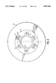
- FIG. 2 depicts the intake manifold of FIG. 1 as viewed from the combustion engine
- FIGS. 3 and 4 illustrate a second embodiment, in which the intake manifold has a multipart design.
- FIGS. 1 and 2 show an intake manifold for a combustion engine, the induction pipe body 1 being constructed of polymer material and having first and second flow-through openings 2 and 6, which are each provided with adjusting elements 3 and 7, respectively, to alter an associated cross-sectional area of passage.
- the first adjusting element 3 is a throttle valve 5, which is secured to a throttle shaft and is supported by this shaft in the intake manifold.
- the second flow-through opening 6 is formed by a cage 9 of a one-way valve 8, which as a non-return valve can only be traversed by flow in the direction of the combustion engine.
- the second flow-through openings 6 are formed as perforations 10 in the cage 9, the perforations 10 being designed to serve as a valve seat 12 that can be forcibly engaged with the elastomeric sealing members 11.
- the intake manifold is flange-mounted directly on the cylinder head in the immediate vicinity of the intake valve of the combustion engine.
- the one-way valve 8 is secured to the front side of the induction pipe body 1 facing the combustion engine, the cage 9 with its inner circumference forming the boundary wall 4 of the first flow-through opening 2.
- the throttle valve is rotatably supported inside the induction pipe body 1.
- the sealing members 11 of the one-way valve 8, which in this exemplary embodiment are made of an elastomeric material, are each secured to the cage 9 in a gas-tight manner by a fastening element 11'.
- the second adjusting element 7 of FIG. 1 is further shown in FIG. 2.
- This illustrative embodiment provides for six second flow-through openings 6, which are distributed uniformly in the circumferential direction.
- the combustion engine (not shown here) is operated in the low speed range, so that the air or the air-fuel mixture only flows through the second adjusting elements 7 and is fed to the combustion chambers.
- the sealing members 11 are designed so that they can be forced automatically into the closed position, given a relative overpressure on the side facing the combustion engine.
- FIG. 3 depicts a second embodiment, which has an intake manifold similar to that of the embodiment of FIG. 1.
- the intake manifold of FIG. 3 has a multipart design, the second adjusting element 7 being arranged between two axially adjacent parts 1.1 and 1.2 of the induction pipe body 1.
- the combustion engine (not shown) is operated at high speed in the full-load state.
- the throttle valve 5 in the first flow-through opening 2 is completely open.
- the second flow-through opening 6 is sealed by the sealing members 11, which engage with the valve seats 1.2.
- the induction pipe body 1 is provided with a spigot 13, inside of which the cage 9 is accommodated. Moreover, it is advantageous that the cage 9 and the induction pipe body 1 form one unit that can be preassembled, as this arrangement offers significant advantages with regard to assembly engineering and with respect to minimizing assembly errors.
Landscapes
- Engineering & Computer Science (AREA)
- Chemical & Material Sciences (AREA)
- Combustion & Propulsion (AREA)
- Mechanical Engineering (AREA)
- General Engineering & Computer Science (AREA)
- Characterised By The Charging Evacuation (AREA)
- Control Of Throttle Valves Provided In The Intake System Or In The Exhaust System (AREA)
- Lift Valve (AREA)
- Cylinder Crankcases Of Internal Combustion Engines (AREA)
Applications Claiming Priority (2)
| Application Number | Priority Date | Filing Date | Title |
|---|---|---|---|
| DE4311744.9 | 1993-04-08 | ||
| DE4311744A DE4311744C2 (de) | 1993-04-08 | 1993-04-08 | Ansaugrohr einer Verbrennungskraftmaschine |
Publications (1)
| Publication Number | Publication Date |
|---|---|
| US5487366A true US5487366A (en) | 1996-01-30 |
Family
ID=6485166
Family Applications (1)
| Application Number | Title | Priority Date | Filing Date |
|---|---|---|---|
| US08/225,198 Expired - Fee Related US5487366A (en) | 1993-04-08 | 1994-04-08 | Intake manifold |
Country Status (4)
| Country | Link |
|---|---|
| US (1) | US5487366A (it) |
| JP (1) | JP2540447B2 (it) |
| DE (1) | DE4311744C2 (it) |
| IT (1) | IT1272188B (it) |
Cited By (5)
| Publication number | Priority date | Publication date | Assignee | Title |
|---|---|---|---|---|
| US5704327A (en) * | 1993-05-05 | 1998-01-06 | Firma Carl Freudenberg | Intake pipe for an internal combustion engine |
| ES2222055A1 (es) * | 1996-10-22 | 2005-01-16 | Cesar Torralba Gimeno | Mejoras introducidas en la patente de invencion n.9602225 por: compensador de vacio para motores de explosion. |
| ES2234372A1 (es) * | 2002-11-05 | 2005-06-16 | Cesar Torralba Gimeno | Compensador de vacio para motores de explosion. |
| CN100513766C (zh) * | 2005-07-07 | 2009-07-15 | 爱三工业株式会社 | 节气阀体 |
| CN102042136A (zh) * | 2010-12-24 | 2011-05-04 | 杨思恩 | 一种机动车用可变进气岐管 |
Families Citing this family (4)
| Publication number | Priority date | Publication date | Assignee | Title |
|---|---|---|---|---|
| DE19501411A1 (de) * | 1995-01-19 | 1996-07-25 | Mann & Hummel Filter | Ansaugvorrichtung für einen Verbrennungsmotor |
| DE19504382A1 (de) * | 1995-02-10 | 1996-08-14 | Mann & Hummel Filter | Ansaugsystem |
| DE19932826A1 (de) * | 1999-07-14 | 2001-01-25 | Mann & Hummel Filter | Rohr mit veränderbarem Ansaugquerschnitt |
| AT511721B1 (de) * | 2011-11-03 | 2013-02-15 | Avl List Gmbh | Einlassstrang für eine brennkraftmaschine |
Citations (3)
| Publication number | Priority date | Publication date | Assignee | Title |
|---|---|---|---|---|
| US4779580A (en) * | 1986-07-03 | 1988-10-25 | Dr. Ing. H.C.F. Porsche Aktiengesellschaft | Suction system for a reciprocating piston internal combustion engine |
| US5179917A (en) * | 1991-05-21 | 1993-01-19 | Toyota Jidosha Kabushiki Kaisha | Intake air control device for an internal combustion engine |
| US5255648A (en) * | 1991-05-21 | 1993-10-26 | Toyota Jidosha Kabushiki Kaisha | Intake air control device for an internal combustion engine |
Family Cites Families (4)
| Publication number | Priority date | Publication date | Assignee | Title |
|---|---|---|---|---|
| JPS60115041A (ja) * | 1983-11-26 | 1985-06-21 | Trio Kenwood Corp | 回転ヘツド式pcmテ−プレコ−ダ |
| IT1229893B (it) * | 1989-02-17 | 1991-09-13 | Alfa Lancia Ind | Dispositivo di alimentazione per un motore a c.i.. |
| JPH0419324A (ja) * | 1990-05-11 | 1992-01-23 | Nissan Motor Co Ltd | 内燃機関の吸気制御装置 |
| JPH04103829A (ja) * | 1990-08-21 | 1992-04-06 | Nissan Motor Co Ltd | 内燃機関の吸気装置 |
-
1993
- 1993-04-08 DE DE4311744A patent/DE4311744C2/de not_active Expired - Fee Related
-
1994
- 1994-03-18 IT ITRM940146A patent/IT1272188B/it active IP Right Grant
- 1994-04-08 JP JP6071118A patent/JP2540447B2/ja not_active Expired - Fee Related
- 1994-04-08 US US08/225,198 patent/US5487366A/en not_active Expired - Fee Related
Patent Citations (3)
| Publication number | Priority date | Publication date | Assignee | Title |
|---|---|---|---|---|
| US4779580A (en) * | 1986-07-03 | 1988-10-25 | Dr. Ing. H.C.F. Porsche Aktiengesellschaft | Suction system for a reciprocating piston internal combustion engine |
| US5179917A (en) * | 1991-05-21 | 1993-01-19 | Toyota Jidosha Kabushiki Kaisha | Intake air control device for an internal combustion engine |
| US5255648A (en) * | 1991-05-21 | 1993-10-26 | Toyota Jidosha Kabushiki Kaisha | Intake air control device for an internal combustion engine |
Cited By (7)
| Publication number | Priority date | Publication date | Assignee | Title |
|---|---|---|---|---|
| US5704327A (en) * | 1993-05-05 | 1998-01-06 | Firma Carl Freudenberg | Intake pipe for an internal combustion engine |
| ES2222055A1 (es) * | 1996-10-22 | 2005-01-16 | Cesar Torralba Gimeno | Mejoras introducidas en la patente de invencion n.9602225 por: compensador de vacio para motores de explosion. |
| ES2222055B1 (es) * | 1996-10-22 | 2006-03-16 | Cesar Torralba Gimeno | Mejoras introducidas en la patente de invencion n.9602225 por: compensador de vacio para motores de explosion. |
| ES2234372A1 (es) * | 2002-11-05 | 2005-06-16 | Cesar Torralba Gimeno | Compensador de vacio para motores de explosion. |
| ES2234372B1 (es) * | 2002-11-05 | 2006-10-01 | Cesar Torralba Gimeno | Compensador de vacio para motores de explosion. |
| CN100513766C (zh) * | 2005-07-07 | 2009-07-15 | 爱三工业株式会社 | 节气阀体 |
| CN102042136A (zh) * | 2010-12-24 | 2011-05-04 | 杨思恩 | 一种机动车用可变进气岐管 |
Also Published As
| Publication number | Publication date |
|---|---|
| DE4311744C2 (de) | 2003-04-17 |
| IT1272188B (it) | 1997-06-16 |
| DE4311744A1 (de) | 1994-10-13 |
| ITRM940146A0 (it) | 1994-03-18 |
| JPH06299919A (ja) | 1994-10-25 |
| ITRM940146A1 (it) | 1995-09-18 |
| JP2540447B2 (ja) | 1996-10-02 |
Similar Documents
| Publication | Publication Date | Title |
|---|---|---|
| US6217001B1 (en) | Pressure balanced gas valve | |
| JP4706775B2 (ja) | 内燃機関の吸気装置 | |
| US5696318A (en) | Air intake for an internal combustion engine | |
| US5487366A (en) | Intake manifold | |
| US7654537B2 (en) | Gasket for a valve in an internal combustion engine | |
| US5511531A (en) | EGR valve with force balanced pintle | |
| US8764019B2 (en) | Gasket for a valve in an internal combustion engine | |
| JP2002501138A5 (it) | ||
| US3788071A (en) | All-metal check valve for air injection system | |
| KR940019986A (ko) | 왕복내연기관의 연료분사밸브 | |
| BRPI0616748A2 (pt) | Válvula para o controle de um fluido | |
| US5778851A (en) | Piston-type internal combustion engine having at least two intake valves per cylinder | |
| US3265084A (en) | Engine crankcase breather valve | |
| US3370785A (en) | Fluid flow control mechanism | |
| US3999737A (en) | Flow control valve for exhaust gas purifying system | |
| US4905657A (en) | Emission control valve with gas flow shut-off | |
| KR930010357A (ko) | 2 행정 엔진 | |
| US4905656A (en) | Emission control valve with internal spring | |
| US4886033A (en) | Stabilized flow control valve | |
| JP2017219162A (ja) | 二重偏心弁 | |
| CN222797581U (zh) | 发动机和车辆 | |
| JPH1185U (ja) | 燃料タンク用コネクタ | |
| US7117837B2 (en) | Unit for supplying combustion air to the cylinders of an endothermic engine | |
| US20080224418A1 (en) | Rotary Valve Internal Combustion Engine and Seal Arrangement | |
| JPS5834305Y2 (ja) | 液体ポンプ |
Legal Events
| Date | Code | Title | Description |
|---|---|---|---|
| AS | Assignment |
Owner name: FIRMA CARL FREUDENBERG, GERMANY Free format text: ASSIGNMENT OF ASSIGNORS INTEREST;ASSIGNOR:DOHRING, KLAUS;REEL/FRAME:006948/0082 Effective date: 19940316 |
|
| FPAY | Fee payment |
Year of fee payment: 4 |
|
| FPAY | Fee payment |
Year of fee payment: 8 |
|
| REMI | Maintenance fee reminder mailed | ||
| LAPS | Lapse for failure to pay maintenance fees | ||
| STCH | Information on status: patent discontinuation |
Free format text: PATENT EXPIRED DUE TO NONPAYMENT OF MAINTENANCE FEES UNDER 37 CFR 1.362 |
|
| FP | Lapsed due to failure to pay maintenance fee |
Effective date: 20080130 |