US5394591A - Autoleveller drafting arrangement with mass fluctuation control - Google Patents
Autoleveller drafting arrangement with mass fluctuation control Download PDFInfo
- Publication number
- US5394591A US5394591A US07/765,570 US76557091A US5394591A US 5394591 A US5394591 A US 5394591A US 76557091 A US76557091 A US 76557091A US 5394591 A US5394591 A US 5394591A
- Authority
- US
- United States
- Prior art keywords
- drafting
- measuring element
- outlet side
- sliver
- side measuring
- Prior art date
- Legal status (The legal status is an assumption and is not a legal conclusion. Google has not performed a legal analysis and makes no representation as to the accuracy of the status listed.)
- Expired - Fee Related
Links
Images


Classifications
-
- D—TEXTILES; PAPER
- D01—NATURAL OR MAN-MADE THREADS OR FIBRES; SPINNING
- D01H—SPINNING OR TWISTING
- D01H5/00—Drafting machines or arrangements ; Threading of roving into drafting machine
- D01H5/18—Drafting machines or arrangements without fallers or like pinned bars
- D01H5/32—Regulating or varying draft
- D01H5/38—Regulating or varying draft in response to irregularities in material ; Measuring irregularities
Definitions
- the present invention relates broadly to textile machines containing drafting arrangements, and, more specifically, to a new and improved autoleveller drafting arrangement and to a method of operating such autoleveller drafting arrangement.
- An autoleveller drafting arrangement is a drafting arrangement at which there can be altered in a controlled or regulated manner the draft of the textile material, in order to even out mass fluctuations at a drafted sliver.
- Such drafting arrangements are frequently used in so-called autolevelling systems in short staple fiber spinning mills, but also can be employed at cards, combing machines and combing preparatory machines in short staple fiber spinning mills. Of course, the same principles are also suitable for use in long staple fiber spinning mills.
- a second embodiment of the same proposal contemplates establishing threshold values for the setting or adjustment signal which governs the drafting operation.
- a threshold value upon exceeding a threshold value there is triggered an alarm and the machine is shutdown.
- the fiber sliver is checked by an operator.
- conclusions are drawn concerning errors in the inlet measuring system or in the production of the feed material or supply stock, that is, at the production machines upstream of such drafting arrangement.
- the monitoring operation is set to merely detect a short-time (possibly seldom) fault occurrence or "runaway” situation, the piece or section of the sliver to be examined by the operator no longer contains a corresponding "event", so that again there exists the risk of reaching a deceptive conclusion.
- Another and more specific object of the present invention aims at further developing autoleveller drafting arrangements in such a manner that the interactions decisive for operation of such autoleveller drafting arrangements can be taken into even better account than considered in the aforementioned U.S. application Ser. No. 07/566,627.
- the present invention contemplates the provision of an autoleveller drafting arrangement for slivers, which is equipped with an outlet measuring element, at least one drafting zone, a drive system and a control or regulation system (sometimes simply generically or broadly referred to herein as a regulation system) for the drive system.
- This control or regulation system responds to a measurement signal delivered by the outlet measuring element, so that by means of the drive system the drafting of the textile material in the drafting zone can be changed in such a manner that mass fluctuations in the feed sliver are corrected.
- the autoleveller drafting arrangement of the present development is manifested, among other things, by the features that the measurement signal of the outlet measuring element is adjusted as a function of the operating conditions in order to compensate effects exerted upon the measurement result due to such operating conditions.
- One such operating condition or more specifically, one such operational parameter is the degree of drafting exerted upon that section of the sliver which is responsible for the measurement signal.
- a further such operating condition or operational parameter is the delivery velocity or speed of the sliver.
- the present invention provides an autoleveller drafting arrangement for slivers having an inlet side and an outlet side, which comprises:
- an outlet measuring element for measuring the drafted sliver and delivering a measurement signal as a result of the measuring of the drafted sliver in order to provide a measurement result
- the regulation means being operatively connected with the outlet measuring element and responsive to the measurement signal delivered by the outlet measuring element for regulating the drive means such that the drafting of the textile material in the drafting zone can be changed in such a manner that mass fluctuations in the at least one feed sliver are corrected;
- said regulation means adjusting the measurement signal of the outlet measuring element as a function of at least one operating condition prevailing at the drafting arrangement in order to compensate effects exerted upon the measurement result due to the at least one operating condition.
- the inlet measuring element can be responsive to both the mass of the textile material delivered from the inlet side of the drafting arrangement and to a quantity of at least one medium or substance entrained by the textile material, such as the moisture content of the textile material or the air entrained between the fibers of the textile material.
- a further aspect of the present invention entails providing means for obtaining from the inlet measuring element a measurement signal comprising two signal components composed of respective signal component pairs, wherein each respective signal component pair is unambiguously correlatable to a predeterminable quantity of fibers of the textile material, and means for correlating signal component pairs to quantities of fibers of the drafted sliver determined by the outlet measuring element while taking into account the action of the at least one drafting zone upon the mass of the fibers of the textile material located between the inlet measuring element and the outlet measuring element.
- the invention is furthermore directed to a method of operating an autoleveller drafting arrangement for slivers having an inlet side and an outlet side, which comprises the steps of:
- an outlet measuring element for measuring the drafted sliver and delivering an output measurement signal representative of the fiber mass of the drafted sliver and air entrained by the fiber mass of the drafted sliver;
- regulating drive means of the at least one drafting zone by regulation means responsive to the output measurement signal delivered by the outlet measuring element such that the drafting of the textile material in the drafting zone can be changed in such a manner that mass fluctuations in the textile material originating from one or more feed slivers are corrected;
- each respective signal component pair being unambiguously correlatable to a predeterminable quantity of fibers of the textile material
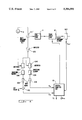
- FIG. 1 schematically illustrates a drafting arrangement containing a preliminary drafting zone or region and a main drafting zone or region and the principle measuring devices in general correspondence with the system disclosed in the commonly assigned, U.S. application Ser. No. 07/552,491, filed Jul. 16, 1990, and entitled “Drafting Arrangement With Feedback Drive Groups", the disclosure of which is incorporated in its entirety herein by reference;
- FIG. 2 illustrates a measuring transducer constituting the inlet measuring element of the drafting arrangement depicted in FIG. 1;
- FIG. 3 illustrates the function principle of the method accomplished with the aforementioned commonly assigned, U.S. application Ser. No. 07/566,627, filed Aug. 13, 1990;
- FIG. 4 depicts in block circuit diagram a simplified version of the method accomplished with the structure depicted in FIG. 3;
- FIGS. 4A and 4B are respective diagrams for explaining evaluation of the signal delivered by the inlet measuring element.
- FIG. 5 is a block circuit diagram of the system for taking into account possible measuring errors at the outlet measuring element.
- FIG. 1 there is schematically depicted an exemplary embodiment of drafting arrangement D of a textile machine, such as a draw frame.
- pre-draft preliminary draft
- the web 18 issuing from the drafting arrangement D is thinner than the web formed by the infed slivers 15.1 to 15.6 and correspondingly longer. Since the drafting operations can be regulated as a function of the cross-section of the infed slivers 15.1 to 15.6, these slivers and, more specifically, the resultant web is evened out during its passage through the drafting arrangement D.
- the drafting arrangement D depicted in FIG. 1 specifically will be seen to comprise a preliminary drafting zone or region 11 and a main drafting zone or region 12. It is to be expressly understood that the teachings of the present invention can be, of course, employed in analogous manner in conjunction with drafting arrangements having only one or more than two drafting zones or regions,
- the infed slivers 15.1 to 15.6 are delivered into the drafting arrangement D by the two roller systems 1 and 2 comprising, for example, conveyor or transport rolls 1.1, 1.2 and 2.1, 2.2 and 2.3, respectively.
- the infed slivers 15.1 to 15.6 grouped or gathered together into a loose fleece or web are transported through the first roller system 1 which comprises, for instance, the just mentioned two rolls or rollers 1.1 and 1.2.
- the second roller system 2 Arranged downstream of the first roller system 1, as viewed with respect to the predetermined direction of travel of the slivers 15.1 to 15.6, is the second roller system 2, here comprising an active or driven conveying or transport roll or roller 2.1 and two passive or non-positively driven conveying or transport rolls or rollers 2.2 and 2.3.
- the infed slivers 15.1 to 15.6 are grouped together adjacent one another to form the composite web 16.
- peripheral velocities v 1 and v 2 (equal to v in ) of all of the rolls 1.1, 1.2 and 2.1, 2.2 and 2.3 of both of the roller systems 1 and 2 of this textile material infeed structure are of approximately the same magnitude, so that the thickness of the web 16 corresponds to the thickness of the infed slivers 15.1 to 15.6.
- a third roller system 3 follows, in the predetermined direction of travel of the web 16, the first and second roller systems 1 and 2 of the previously considered textile material infeed structure.
- This third roller system 3 comprises the preliminary or pre-draft rolls or rollers 3.1 and 3.2. between which the web 16 is further transported.
- the peripheral velocity v 3 of the preliminary draft rolls 3.1 and 3.2 is greater than the peripheral velocities v 1 and v 2 of the rolls 1.1 and 1.2 of the roller system 1 and the rolls 2.1, 2.2 and 2.3 of the roller system 2. Consequently, the web 16 is drafted between the transport or infeed rolls 2.2 and 2.3 of the roller system 2 and the preliminary draft rolls 3.1 and 3.2 of the roller system 3 in the preliminary drafting zone 11, and the cross-section of such web 16 is reduced.
- a further or fourth roller system 4 follows the roller system 3 containing the preliminary draft rolls 3.1 and 3.2 in the predetermined direction of travel of the preliminary drafted web 17.
- This further roller system 4 comprises, for example, an active or driven roll or roller 4.1 and two passive or non-positively driven rolls or rollers 4.2 and 4.3 for the further transport of the web 17.
- the peripheral velocity v 4 of these transport or conveying rolls 4.1, 4.2 and 4.3 of the roller system 4 is the same as the peripheral velocity v 3 of the preliminary draft rolls 3.1 and 3.2 of the roller system 3.
- a fifth roller system 5 containing the main draft rolls 5.1 and 5.2 follows the fourth roller system 4 in the predetermined direction of travel of the web 17.
- these main draft rolls 5.1 and 5.2 have a greater peripheral velocity v 5 than the peripheral velocity v 4 of the upstream located transport or conveying rolls 4.1, 4.2 and 4.3 of the fourth roller system 4, so that the preliminary drafted web 17 is further drafted in the main drafting zone 12, between the rolls 4.1, 4.2 and 4.3 and the main draft rolls 5.1 and 5.2, in order to form the finished or final drafted sliver 18.
- This finally drafted web 18 is condensed or gathered together by the condenser or funnel T to form a sliver 18'.
- the finally drafted sliver 18' is removed from the drafting arrangement D by a roller pair 6 composed of the delivery or outfeed rolls or rollers 6.1 and 6.2 having a peripheral velocity v 6 (v out ) which is equal to the peripheral velocity v 5 of the upstream located main draft rolls 5.1 and 5.2.
- the removed sliver 18' is deposited, for example, into rotating sliver cans 13.
- the roller systems 1, 2 and 4 are driven by a first drive motor or drive 7.1 by means of a suitable transmission, preferably toothed belts, generally indicated by reference numeral 7a.
- the preliminary draft rolls 3.1 and 3.2 of the roller system 3 are mechanically coupled, as schematically indicated by the coupling line 4a, with the roller system 4, specifically, for example, with the driven roll or roller 4.1 thereof, and the transmission ratio can be adjusted relative to the roller systems 1 and 2 or there can be preset a reference or set value.
- the transmission determines the ratio between the peripheral velocities v in , that is the peripheral velocities v 1 and v 2 of the rolls 1.1, 1.2 and 2.1, 2.2 and 2.3 of both of the roller systems 1 and 2 and the peripheral velocity v 3 of the preliminary draft rolls 3.1 and 3.2 of the roller system 3 together with the preliminary drafting ratio.
- the infeed or transport rolls 1.1 and 1.2 of the roller system 1, as explained above, can be driven by the first drive motor 7.1 or else, if desired, directly by an independent drive motor 7.3.
- roller systems 5 and 6 are driven by a second drive motor or drive 7.2 through the action of a suitable transmission, again preferably toothed belts, generally indicated by reference numeral 7b.
- a suitable transmission again preferably toothed belts, generally indicated by reference numeral 7b.
- both of the drive motors or drives 7.1 and 7.2 have operatively associated therewith their own regulator or controller 8.1 and 8.2, respectively.
- the regulation or control operation is accomplished by a respective closed regulation circuit 8a, 8b and 8c, 8d provided for the regulators or controllers 8.1 and 8.2, respectively.
- any one drive motor 7.1 or 7.2 can be transmitted in one or the other direction to the other drive motor 7.2 or 7.1 by a control connection 8e interconnecting the regulators or controllers 8.1 and 8.2, so that each such drive motor 7.1 and 7.2 can appropriately respond to reference or set value deviations of the other drive motor.
- the entire cross-section or cross-sectional area of the infed slivers 15.1 to 15.6 is measured by an inlet measuring or measurement element or means 9.1.
- the cross-section or cross-sectional area of the emerging sliver 18 is measured by an outlet measuring or measurement element or means 9.2.
- a central computer unit 10 transmits an initial setting of the reference or set value for the first drive motor or drive 7.1 by means of the connection or transmission line 10a to the first regulator 8.1.
- the measurement or measuring values of both of the measuring elements 9.1 and 9.2 are continuously transmitted during the drafting operation by means of the connection or transmission lines 9a and 9b to the central computer unit 10.
- the reference or set value for the second drive motor or drive 8.2 is determined by the central computer unit 10 and possibly provided further elements according to the invention from these measurement values or results and from the reference or set value for the cross-section of the emerging sliver 18'.
- This reference or set value is continuously inputted by the connection or transmission line 10b to the second regulator 8.2.
- the regulators or controllers in the auxiliary regulation are advantageously position regulators or controllers (not rotational speed regulators), since such position regulators or controllers permit carrying out the regulation operation also in the event of standstill of a drive motor.
- the corresponding regulators 8.1 and 8.2 (and possible further regulators as contemplated according to a variant embodiment) can contain separate computer units (for example, having digital computer elements; microprocessors) or, however, can be designed as modules of the central computer unit 10.
- the objective is to produce a constant or essentially constant preliminary draft.
- the sliver cross-section is controlled and equalized substantially by varying the draft in the main drafting zone 12.
- the inlet measuring element 9.1 delivers the inlet-side measuring signal containing information about the cross-section of the infed slivers 15.1 to 15.6.
- the dielectric constant ⁇ w of water is 81, as compared with the dielectric constant ⁇ B of cotton, which is about 4.
- the difficulty is to obtain the desired signal directly via the transducer and by using the fiber mass which is in the capacitor at a given time.
- the voltage U is measured across the capacitor 21 and the resulting signal is divided into a real part R x and an imaginary part C x .
- Signals R x and C x are evaluated in the regulation system, as will be explained more fully hereinafter, and also while taking account of the outlet measurement or measured signal.
- the difficulties in measurement on the input or inlet side are one reason for constructing the regulation system according to the invention in such a manner that errors in measurement are compensated by adaptive regulation or control.
- the outlet measuring element 9.2 can be a conventional measuring instrument which delivers a signal A out containing data or information about the cross-section of the emerging sliver 18'. This signal also is subsequently additionally processed for regulation purposes.
- the required measurements need not be only made directly at the inlet or outlet. It is only necessary to dispose one measuring element or means in front, that is, in an upstream zone, and one behind, that is, in a downstream zone, with respect to the regulated or controlled system, that is, the main drafting zone 12 in the present case. It would also be advantageous, for example, to dispose the input-side or input-end measuring element 9.1 immediately in front or upstream of the main drafting zone 12, to obtain advantageous time-dependence of the regulation accomplished by the regulation system.
- the regulation needs to keep the mean or average value of the sliver substantially constant (the first priority) and also to eliminate irregularities in the sliver.
- the deviations of the regulated or controlled variables or magnitudes can be detected by the regulation or control system as high-frequency and low-frequency components of the measured variables or magnitudes.
- the problem as regards measurement technology and automatic regulation or control engineering is to obtain information about these variables or magnitudes and convert them into the desired manipulated or adjustment variable or magnitude. In particular, in the case of high-frequency changes, there must be taken into account the transit time between the measuring element and the final control or adjustment element.
- FIG. 3 illustrates the regulation or control principle and the method according to the invention, in a schematic diagram of the main regulation or control system.
- the drafting arrangement is indicated by arrows representing the direction of travel of the sliver, as well as a block 11 for the preliminary draft and a block 12 for the main draft.
- the actual cross-section m E of the slivers 15.1 to 15. 6 at the inlet is represented by the variable or magnitude m e
- the actual cross-section m A of the already finished drafted sliver 18' is represented by the variable or magnitude m a .
- the slivers 15.1 to 15.6 are delivered at the inlet at a speed v in and the finished drafted sliver 18' emerges at the outlet at a speed v out .
- the amount of preliminary draft or drafting K1 can be adjusted by a presetting means 19.
- the regulation path, in terms of the regulation, is formed by the main drafting zone 12 in the present case.
- the transit time between the inlet measuring element or means 9.1 and the main drafting zone 12 is denoted by reference character t1
- the transit time between the main drafting zone 12 and the outlet measuring element or means 9.2 is denoted by reference character T2.
- the measured magnitudes or variables A out , R x , and C x are the input variables or magnitudes to a regulation or control system.
- the regulation or control system comprises a central computer unit 10 which is supplied with the measured magnitudes or variables C x , R x , the temperature I T at input 10c and any additional data or information I 1-n at input 10d, such as the air humidity, air pressure and so forth.
- the magnitude or variable A set is set as the guide magnitude or variable.
- a first path 1 contains the central computer unit 10 with inlet and outlet leads, that is, inputs and outputs, and a number of time function elements Z1.1-Z3 and is used according to the invention for processing measured data.
- a second path 2 is for optimizing the delay time t1.
- a third path 3 is for optimizing the process of keeping the sliver mean value constant, and compensating long-term defects.
- a fourth path 4 is provided for optimized compensation of short-term defects.
- the regulation or control system used in the invention is preferably digital, so that all of the components of the regulation or control system can be embodied in a computer. In order to illustrate the regulation or control principle, the essential components necessary for understanding the invention are diagrammatically illustrated in FIG. 3.
- a comparator 35 is provided and forms the difference between the output signal A out and the set value A set .
- the thus-determined deviation dA is fed through an I-element 38 to an adder 36.
- the deviations from the mean value are integrated in I-element 38, forming the signal Am, and unity is added.
- the deviation is added in a second adder 37 to deviations ⁇ h caused by short-term disturbances or defects and determined in path 1 and path 4 as explained hereinafter, and finally the factor 1+ ⁇ m+ ⁇ h is multiplied in a multiplier 39 by the preset nominal value K3 of the main draft.
- the corresponding multiplication gives the required adjustment magnitude or manipulated variable y for controlling the main draft.
- the outlet measured signal A out is also fed to a high-pass element or filter 47 of path 2.
- the filtered signal is squared by a multiplier 40 to obtain the signal ⁇ H, which gives the high-frequency component of the fluctuations in the mean value.
- account is taken of the high-frequency components, which in this embodiment are up to about 300 Hz.
- the signal ⁇ H is fed to a first regulation or control unit R1 having a transmission function for minimalizing ⁇ H.
- the regulation or control element R1 outputs the signal S t1 , which has an optimizing influence on the delay time of various time function elements Z1.1, Z1.2, Z4 and is directly fed to the central computer unit 10.
- the core or salient member connecting path 1 and path 4 is an identification-field or performance characteristic element 50.
- Identification-field element 50 can, for example, be a read-write memory and can be incorporated in the central computer unit 10.
- the identification-field element 50 is supplied with the measured pairs of values R x , C x and delivers the magnitude or variable m e as the output signal.
- the identification field or performance characteristic is continuously adjusted during operation, the adjustment being made in path 1.
- the signals R x , C x after being delayed in corresponding time function elements Z1.1-Z2.2, are fed to the central computer unit 10.
- the time function elements Z1.1-Z2.2 serve to take account of the entire transit time t1+T2 from the inlet measuring element or means 9.1 to the outlet measuring element or means 9.2.
- the filtered variable m e (t1) after being delayed to allow for the transit time t1 and after being draft-compensated in a divider 43, is supplied via a time function element Z3 to an additional input 10e of the central computer unit 10.
- the signal A out containing information or data about the outlet sliver cross-section m A represented by the measured magnitude or variable m a , is preferably likewise filtered prior to being delivered to the central computer unit 10.
- the low-frequency signal components are clipped in a suitable filter 46 in path 1.
- the transit time t1 can alternatively be taken directly into account by the central computer unit 10, by feeding thereto the output signal S t1 in path 2.
- All of the signals delivered to the central computer unit 10 are subsequently used for correcting the identification field or performance characteristic of identification-field element 50, for which purpose the ("effective") magnitude or variable m e relating to the respective pair of values C x , R x , and obtained by evaluating the measured data, constitute the output of the central computer unit 10 and are transmitted to the identification-field element 50.
- the identification field is permanently adapted to changes within the regulation or control process.
- the central computer unit 10 must evaluate at least the signals m e , R x , C x , m a in order to ensure that the identification field is adapted. Under certain conditions, however, the aforementioned additional measurement data I T , I 1-n can be used for further improvement of the regulation or control.
- the signal A out is filtered, but this time by a band-pass element or filter 48 instead of a high-pass element or filter.
- the band-pass element 48 is followed by a multiplier 44 and a regulation or control unit R2 for minirealizing the corresponding signal ⁇ B.
- the regulation or control unit R2 outputs a factor f B which is multiplied by the signal m e (t1) in a multiplier 42.
- the signal m e (t1) appears at the output of a filter 49, to which the signal m e from the identification-field element 50 is supplied via the time function element Z4. Filter 49 clips the low-frequency components of the signal.
- Path 4 also contains a threshold-value switch 25 having an adjustable preset value ⁇ to both sides of the mean value. If the signal m e (t1) is below the preset value ⁇ , that is, within the tolerance band or limits about the mean value, then the threshold-value switch 25 will be in a first position p1. As soon as the preset value ⁇ is exceeded in the one or other direction, that is, m e fluctuates widely around the mean value, the threshold-value switch 25 changes to a position p2 at which the signal m e (t1) travels directly to path 3, so that these fluctuations are fully taken into account for the main draft.
- path 4 is used for optimization.
- the signal m e (t1) is multiplied in multiplier 42 by the factor f B determined by means of the minimalization function of the regulation or control unit R2, and the output signal from the multiplier 42 is supplied to path 3 via the threshold-value switch 25.
- the switching-over by means of the threshold-value switch 25 and the optimization which is taken into account by the regulation or control unit R2, serves to prevent any disturbances caused, for example, by noise from being introduced into path 3 during small or very small temporary deviations from the mean value.
- the threshold-value switch 25 is also used for switching on or off the optimization by the regulation or control units R1 and R2. Optimization by the regulation or control units R1 and R2 is switched off if m e is above the preset value ⁇ , and switched on otherwise. It is not absolutely necessary to switch off the optimization by the regulation or control units R1 and R2 if the preset value ⁇ is exceeded, but running away of the corresponding regulation or control also can be achieved by compensation elements. In a digital regulation or control system, however, switching the corresponding regulators or controls on and off is very simple, so that this variant is preferred. After switching-off the optimization by the regulator or controller R1 the last switched-in time-delay t1 remains unchanged until re-newed switching-in of the optimization by the regulator or controller R1.
- the threshold-value switch 25 can also be embodied by a non-linear device or can be incorporated in the identification field or performance characteristic .
- the identification-field or performance characteristic element 50 delivers both the output variable m e and also the required signal for activating or deactivating the optimization by regulation or control units R1 and R2, or delivers a parameter dependent on amplitude.
- the high-pass element or filter in path 2 can filter, for example, frequencies above 100 Hz, whereas the band-pass element or filter can filter frequencies in the range from 10 to 100 Hz.
- the frequency ranges depend on the transit speeds of the slivers, which in the present case are assumed to be in the range of about 600 meters per minute.
- the transmission functions of the regulation or control units R1 and R2 can vary with the construction of the regulation or control system.
- the filters in paths 2 and 4 can be omitted and the transmission functions can be determined in a manner which takes the frequencies in question into account in the required manner.
- the filter 46 in path 1 also can be omitted and filtering can be carried out by the central computer unit 10.
- Another advantage of being able to alter the parameters of the corresponding transmission functions is ease of adaptation to different operating conditions (for example, variations in the throughput speed of the slivers).
- a specific embodiment comprises adaptive adjustment of the regulation or control parameters.
- the parameters of the transmission functions of the regulation or control units R1 and R2 are altered during the regulation or control, so that the variations of the adjustment magnitude or manipulated variable are minimized.
- the parameters of the transmission functions are determined by the central computer unit 10, using the measured magnitudes or quantities.
- adaptive regulation or control great stress must be laid on stability, which can be realized by appropriate determination of the corner values of the identification field or performance characteristic.
- the central computer unit 10 is preferably a digital computing apparatus.
- the functions of the various paths 1-4 explicitly shown in FIG. 3 for explaining the principle of operation can be partly or completely integrated in a single computer.
- the starting identification field or performance characteristic for m e can be obtained, for example, by static measurements at the measuring capacitor 21 and then stored in the form of a table. It is to be noted that other identification fields or performance characteristics have to be determined if the method of measurement is varied. Accordingly, the inventive principle can be applied to other inlet and outlet measuring elements, using corresponding identification fields or performance characteristics.
- the regulation or control principle according to the invention ensures excellent homogenizing or equalization even if there are unforeseen changes in operating conditions. More particularly, measuring errors on the inlet side are also compensated by the regulation or control. Short-term defects and also slow changes can both be compensated in optimum manner by the regulation or control. If the aforementioned method is used for the main regulation or control of the drafting unit in conjunction with the auxiliary regulation or control of the independent drive groups and a corresponding interlinked regulation or control is provided, the conditions are particularly advantageous. Accordingly, the adjustment magnitude or manipulated variable y determined by the main regulation or control is used as a set value for the regulator or controller 8.2 of the drive for the main drafting zone 12.
- the methods and regulation or control according to the invention are suitable for all devices in the textile industry which require regulation or control of a drafting unit, and are not limited to the draw frame mentioned in the description.
- FIG. 4 illustrates a simplified version of FIG. 3.
- FIG. 4 depicts the inlet measuring element or means 9.1 and the outlet measuring element or means 9.2, the preliminary drafting or pre-draft zone 11, the main drafting zone 12 and the central computer unit 10 with its inputs for the signals R x , C x , A set , A out , 1 t and 1 i-n .
- This FIG. 4 underscores the fact that all regulation operations are realized in the computer software, that is, the "elements" of the paths 1, 2, 3 and 4 of FIG. 3 constitute aspects of the programming of the central computer unit 10.
- the magnitude m e should represent the mass of the fibers located in the measuring field or region of the inlet measuring element 9.1.
- the individual signal components R x and C x do not correspond to this mass magnitude m e because they are dependent upon at least one further variable (the "parameter").
- the "parameter” it is possible to determine for this important parameter a "family" of curves representative of the course of both of the individual signal components R x and C x as a function of the fiber mass, that is, as a function of the magnitude m e for random selected values of the parameter. This has been depicted in the diagram (signal component C x ) of FIG. 4A and in the diagram (signal component R x ) of FIG.
- FIGS. 4A and 4B each respectively show three characteristics, namely, a characteristic for 10% water, one for 20% water and the remaining one for 30% water.
- FIG. 4B shows horizontal "curves" which is not quite true in actual practice, but can be assumed to be so as a good approximation).
- the identification field or performance characteristic there are accordingly inserted (read into a storage or memory of the central computer unit 10) individual correlations of empirically determined signal component pairs R x and C x to known fiber masses, more precisely, known fiber- and water masses, in the identification field .
- a theoretically computed "model" of the identification field then enables the extrapolation of the empirically determined values in order to form a sufficiently extensive and detailed identification field (as a first approximation), so as to cover the desired working or operating region (fiber mass and water content) with the desired precision.
- the regulation or control system now can work (however, not optimized) with this identification field which has been derived partially theoretically, partially empirically.
- outlet measuring element or means 9.2 has a different construction than that of the inlet measuring element or means 9.1 and responds directly to the fiber mass (or the cross-section of the sliver).
- a preferred construction of outlet measuring element means comprises a feeler roll pair, for instance, as disclosed in the commonly assigned U.S. Pat. No. 4,539,729, granted Sep. 10, 1985, to which reference may be readily had and the disclosure of which is incorporated in its entirety herein by reference.
- This reconstructed value of the fiber mass in the feed sliver is correlated, as the magnitude m e in the identification field to the relevant signal component pair R x and C x , and there is erased the original (theoretical) computed value of the magnitude m e for this signal component pair R x and C x .
- the regulation or control system After a certain period of "experience", the regulation or control system has formed in this manner its own identification field or performance characteristic which has been tailored thereto and can correspondingly operate in an optimized fashion.
- a single "disturbance factor” namely, the water or moisture content of the sliver.
- disturbances Belonging to such disturbances are, for example, changes in the air humidity which affect draftability of the sliver and the delivery velocity or speed which can influence the behavior of the regulation or control system or circuit.
- the changeable variables as "parameter" and for different values of this parameter to form a respective identification field or performance characteristic. There is then switched over from one identification field or performance characteristic to the other as a function of, for example, a signal at the input carrying the previously mentioned data 1 1-n or as a function of the setting of the delivery velocity.
- the regulation or control system will be affected due to aging of the inlet measuring element 9.1 or the outlet measuring element 9.2 or the drafting rolls, so that the behavior of the regulation or control system changes with time.
- a change in the type of textile material undergoing processing also can result in a change in the behavior of the regulation or control system.
- such changes can be taken into account through continual adjustment or correction of the identification field or performance characteristic .
- the inlet measuring element 9.1 delivers two signal components R x and C x which can be unambiguously correlated as a pair to a predeterminable fiber mass and that this determination can be accomplished based upon the signal delivered by the outlet measuring element and known or determinable parameters of the regulated system.
- FIG. 4 illustrates a possibility of realizing this signal division.
- the inlet measuring element or means 9.1 comprises a capacitor 9.1', an amplifier 100 and two rectifiers or rectifier units 102 and 104, each equipped with a smoothing element 106 and an amplifier 108.
- a suitable alternating-current source Q delivers electrical energy at a suitable frequency to the capacitor 9.1' and also to the rectifiers 102 and 104.
- One of the rectifiers 102 and 104, here the rectifier 102 is powered in-phase and the other rectifier 104 90° out-of-phase with respect to the capacitor 9.1'.
- the rectifier 104 delivers a signal representative of 1/R x and the other rectifier 102 delivers a signal to an adder or addition element 110 where such signal is combined with a set or reference value Co corresponding to the capacitance of the "empty" capacitor 9.1', that is when there is not present a sliver.
- the output line of the adder 110 carries the signal C x in the form of deviations with respect to the set or reference value Co.
- the inventive system can provide an additional advantage, namely, when the inlet measuring element or means can not deliver absolute values, only relative results. This is the case, for instance, where, as in FIG. 2, the inlet measuring element is constructed as a capacitor.
- the outlet measuring element or means 9.2 plays an important role both in terms of the regulation (path 3 of FIG. 3) for maintaining constant the mean value of the delivered sliver as well as also for the regulation or control (paths 1, 2 and 4 of FIG. 3) for equalizing short-wave mass fluctuations.
- the inlet measuring element 9.1 must be responsive to a web (FIG. 2), the outlet measuring element 9.2 can be placed at a measuring location following the condensing or gathering of the drafted web into a sliver (in the condenser or funnel T of FIG. 1).
- Charges in the packing density of the fibers of the sliver are responsible for fluctuations in the quantity of entrained air.
- the quantity of air in the sliver during the measurement operation is also dependent upon how much air is expressed or squeezed out during compression of the sliver.
- Both the packing density of the fibers of the sliver and the resistance opposing the squeezing out of the air essentially depend upon the degree of parallelization of the fibers.
- This degree of parallelization of the fibers of a sliver delivered by a drafting arrangement depends, on the one hand, upon the degree of parallelization of the fibers of the feed material and, on the other hand, upon the draft performed in the drafting arrangement. Since the draft continually changes in an autoleveller drafting arrangement, there is to be expected a variable packing density of the fibers in the delivered sliver, and thus, a variable proportion of air throughout the cross-section of the sliver.
- FIG. 5 schematically illustrates a "hardware" solution, which also can be realized by appropriately programming the central computer unit 10.
- This proposal encompasses a "signal transmitter" 120, for example, the element 43 of FIG. 3, which delivers a signal dependent upon the drafting operation to a time-shift element 122, for instance, the element Z3 of the arrangement of FIG. 3.
- the time-shifted or time-displaced signal is delivered to a threshold-value switch 124, so that upon exceeding the threshold value, corresponding to a predetermined degree of drafting or drafting level, there is further delivered a correction signal via an amplifier 126 to an adder or addition element 128.
- This adder 128 also receives the output signal A out of the outlet measuring element or means 9.2 and adds this signal to the correction signal when the latter is received by the amplifier 126. The result is delivered by the output 130 to the paths 1, 2, 3 and 4 for evaluation. In the event there is not generated any correction signal, because the threshold determined by the threshold-value switch 124 has not been exceeded, then the adder 128 simply further delivers the output signal A out , without correction, by means of the output 130.
- the degree of parallelization of the fibers in the delivered sliver is not only dependent upon the drafting which has been carried out, but also upon the degree of parallelization of the fibers in the feed material.
- the correction of the output signal of the outlet measuring element or means 9.2 becomes correspondingly more important the earlier that the autoleveller drafting arrangement is incorporated into the processing line; and a suitable correction is also dependent upon this "environmental factor”. Therefore, in practice, it is advantageous to use as the amplifier 126 an adjustable amplifier, so that at this location of the processing line there can be accommodated the correction signal.
- threshold-value switch 124 Use of the threshold-value switch 124 is not absolutely necessary. A signal dependent upon the degree of drafting can be continuously delivered to the amplifier 126, so that the output signal A out is always corrected as a function of the degree of drafting. Also, two or more threshold values could be defined, which initiate different corrections and these corrections are constituted by known empirical values.
- a further problem in evaluating the output signal delivered by the outlet measuring element is constituted by the previously mentioned squeezing out or expulsion of the entrapped air during the measuring operation or method. This effect is also dependent upon the delivery velocity of the sliver. The greater such delivery velocity the less the amount of entrapped air which can be expressed from the sliver by the roll pair of the outlet measuring element. Therefore, an increase in the delivery velocity of the sliver results in an apparent reduction in the sliver cross-section (the fiber mass).
- the output signal of the outlet measuring element is a function of the instantaneous delivery velocity (at least during stopping or run-up-to-speed of the drafting arrangement).
- the correction is not shown in detail in FIG. 5, since it essentially can be accomplished in the manner of the illustrated and considered draft correction.
- the correction signal is, of course, not derived from the draft, rather from the delivery velocity of the sliver and is furnished to a suitable location, for instance, to the adder 128 where it can be combined with the output signal of the outlet measuring element 9.2.
Landscapes
- Engineering & Computer Science (AREA)
- Mechanical Engineering (AREA)
- Textile Engineering (AREA)
- Preliminary Treatment Of Fibers (AREA)
- Spinning Or Twisting Of Yarns (AREA)
Applications Claiming Priority (2)
| Application Number | Priority Date | Filing Date | Title |
|---|---|---|---|
| CH3100/90 | 1990-09-26 | ||
| CH310090 | 1990-09-26 |
Publications (1)
| Publication Number | Publication Date |
|---|---|
| US5394591A true US5394591A (en) | 1995-03-07 |
Family
ID=4248624
Family Applications (1)
| Application Number | Title | Priority Date | Filing Date |
|---|---|---|---|
| US07/765,570 Expired - Fee Related US5394591A (en) | 1990-09-26 | 1991-09-25 | Autoleveller drafting arrangement with mass fluctuation control |
Country Status (4)
| Country | Link |
|---|---|
| US (1) | US5394591A (de) |
| EP (1) | EP0477589B1 (de) |
| JP (1) | JPH04245931A (de) |
| DE (1) | DE59107714D1 (de) |
Cited By (9)
| Publication number | Priority date | Publication date | Assignee | Title |
|---|---|---|---|---|
| GB2326888A (en) * | 1997-07-01 | 1999-01-06 | Truetzschler & Co | Regulated drawing system for fibre material |
| US6286188B1 (en) * | 1997-09-01 | 2001-09-11 | Maschinenfabrik Rieter Ag | Regulated drawing frame |
| US20020067410A1 (en) * | 2000-12-04 | 2002-06-06 | Achim Breuer | Draw frame including a sliver quality sensing camera |
| FR2821090A1 (fr) * | 2001-02-16 | 2002-08-23 | Truetzschler Gmbh & Co Kg | Dispositif sur un banc d'etirage autoregulateur pour determiner des valeurs de reglage de l'etirage preliminaire |
| FR2833621A1 (fr) * | 2001-12-19 | 2003-06-20 | Truetzschler & Co | Dispositif dans un banc d'etirage, pour determiner des valeurs de reglages pour l'etirage preliminaire |
| US6581248B1 (en) * | 1997-01-23 | 2003-06-24 | Maschinenfabrik Rieter Ag | Carding machine with drawing rollers at the outlet |
| US20050278900A1 (en) * | 2002-08-10 | 2005-12-22 | Joachim Dammig | Method and device for drafting at least one sliver |
| US9873960B2 (en) * | 2013-12-02 | 2018-01-23 | Rieter Ingolstadt Gmbh | Textile machine with variable tension draft |
| CN111058132A (zh) * | 2020-01-06 | 2020-04-24 | 北京经纬纺机新技术有限公司 | 并条匀整死区精确测量系统及测量方法 |
Families Citing this family (9)
| Publication number | Priority date | Publication date | Assignee | Title |
|---|---|---|---|---|
| DE4306343C1 (de) * | 1993-02-25 | 1994-07-14 | Grosenhainer Textilmaschbau | Verfahren zur Vergleichmäßigung von textilen Faserbändern |
| DE4441067A1 (de) * | 1993-12-20 | 1995-06-22 | Truetzschler Gmbh & Co Kg | Regulierstreckwerk für Faserbänder an einer Strecke mit einem Einlaufmeßorgan |
| DE19921429B4 (de) * | 1998-06-29 | 2017-03-02 | Rieter Ingolstadt Gmbh | Verfahren und Vorrichtung zur Fehlerkorrektur eines von einem Meßorgan gelieferten Meßwertes von Faserband in einer Textilmaschine |
| DE19908371A1 (de) * | 1999-02-26 | 2000-08-31 | Truetzschler Gmbh & Co Kg | Vorrichtung an einer Strecke zur Verarbeitung eines Faserverbandes aus Faserbändern |
| DE10140645B4 (de) * | 2000-08-23 | 2011-11-24 | Rieter Ingolstadt Gmbh | Verfahren zum Betreiben eines Streckwerks sowie Streckwerk |
| DE10057699A1 (de) * | 2000-11-21 | 2002-05-23 | Truetzschler Gmbh & Co Kg | Vorrichtung an einer Strecke zur Verarbeitung von Faserbändern, z. B. Baumwolle, Chemiefasern u. dgl. |
| DE10153999B4 (de) * | 2001-11-02 | 2011-07-14 | Rieter Ingolstadt GmbH, 85055 | Simulationsverfahren für eine Spinnereimaschine, Spinnereimaschine, sowie Softwareprogamm-Erzeugnis |
| DE10214955B9 (de) * | 2002-04-04 | 2017-06-29 | Rieter Ingolstadt Gmbh | Spinnereivorbereitungsmaschine |
| DE10335856A1 (de) * | 2003-08-06 | 2005-03-03 | Rieter Ingolstadt Spinnereimaschinenbau Ag | Verfahren und Vorrichtung zum Messen der Bandmasse und/oder der Bandmasseschwankungen eines laufenden Faserverbandes sowie Spinnereivorbereitungsmaschine mit einer Messvorrichtung |
Citations (26)
| Publication number | Priority date | Publication date | Assignee | Title |
|---|---|---|---|---|
| GB824070A (en) * | 1956-10-18 | 1959-11-25 | Fielden Electronics Ltd | Improvements relating to textile drafting eqipment |
| US2930084A (en) * | 1955-10-28 | 1960-03-29 | Bates Mfg Co | Apparatus for corrective drafting of strands of discontinuous fibers |
| US2950508A (en) * | 1954-12-31 | 1960-08-30 | Zellweger Uster Ag | Method and apparatus for automatically controlling the weight per unit length of textile materials |
| US3088175A (en) * | 1958-01-10 | 1963-05-07 | Aoki Akira | Automatic level control system for product sliver weight |
| US3099048A (en) * | 1958-01-09 | 1963-07-30 | Zellweger Uster Ag | Apparatus for automatically controlling the drafting of elongate materials |
| US3925850A (en) * | 1973-11-01 | 1975-12-16 | Fibers Controls Corp | Density sensing and controlling equipment |
| US3958305A (en) * | 1972-10-30 | 1976-05-25 | Zellweger, Ltd. | Method of and an apparatus for uniformalizing combing machine slivers |
| US4038723A (en) * | 1974-02-28 | 1977-08-02 | Zellweger, Ltd. | Method of and an arrangement for standardizing comber slivers |
| US4163927A (en) * | 1977-05-04 | 1979-08-07 | Fiber Controls Corporation | Auto-leveler circuit |
| GB2061338A (en) * | 1979-09-27 | 1981-05-13 | Elitex Zavody Textilniho | Method of and Device for Compensating Errors in Sliver Density Control in Textile Machines |
| GB2062712A (en) * | 1979-10-13 | 1981-05-28 | Zinser Textilmaschinen Gmbh | Drawframes |
| GB2081758A (en) * | 1980-08-12 | 1982-02-24 | Le Nii Textilnoi | Regulating Apparatus for Automatically Controlling the Evenness of the Linear Density of a Sliver |
| US4336684A (en) * | 1979-03-23 | 1982-06-29 | Zinser Textilmaschinen Gmbh | Driving assembly for ring spinning or twisting machine |
| FR2521597A1 (fr) * | 1982-02-18 | 1983-08-19 | Zinser Textilmaschinen Gmbh | Banc d'etirage pour metier a filer |
| US4494204A (en) * | 1981-05-20 | 1985-01-15 | Trutzschler Gmbh & Co. Kg | Carding machine or roller card |
| US4539729A (en) * | 1981-10-29 | 1985-09-10 | Rieter Machine Works Ltd. | Apparatus for the continuous compression or determination of the mass of a fiber sliver |
| US4653153A (en) * | 1984-09-25 | 1987-03-31 | Zellweger Uster Ltd. | Method and device for the optimization of the drawing process on autoleveller drawframes in the textile industry |
| US4703431A (en) * | 1983-09-05 | 1987-10-27 | Chuba Seiko Co., Ltd. | Sliver drawing apparatus |
| DE3622584A1 (de) * | 1986-07-04 | 1988-01-07 | Zinser Textilmaschinen Gmbh | Verfahren und vorrichtung zur regulierung des verzugs eines faserbands bei einer textilmaschine |
| US4791706A (en) * | 1986-05-24 | 1988-12-20 | Tr/u/ tzschler GmbH & Co. KG | Method and apparatus for evening the sliver produced by a card |
| US4812993A (en) * | 1986-06-07 | 1989-03-14 | Zinser Textilmaschinen Gmbh | Method and means for controlling the drafting of sliver in a draw frame |
| US4864694A (en) * | 1986-10-17 | 1989-09-12 | Zinser Textilemaschinen Gmbh | Apparatus for controlling the sliver drafting arrangement in a textile draw frame |
| EP0340756A1 (de) * | 1988-05-04 | 1989-11-08 | Trützschler GmbH & Co. KG | Verfahren und Vorrichtung zur Überwachung des Vergleichmässigens mindestens eines Faserverbandes in einem Regulierstreckwerk |
| US4974296A (en) * | 1990-02-23 | 1990-12-04 | Platt Saco Lowell Corporation, Inc. | Apparatus for correcting irregularities in a textile strand |
| US4987734A (en) * | 1988-02-12 | 1991-01-29 | Rieter Machine Works, Ltd. | Ring spinning machine |
| US5134755A (en) * | 1989-08-11 | 1992-08-04 | Maschinenfabrik Rieter Ag | Method and apparatus for controlling a drafting unit |
-
1991
- 1991-09-02 DE DE59107714T patent/DE59107714D1/de not_active Expired - Fee Related
- 1991-09-02 EP EP91114720A patent/EP0477589B1/de not_active Expired - Lifetime
- 1991-09-25 US US07/765,570 patent/US5394591A/en not_active Expired - Fee Related
- 1991-09-26 JP JP3247249A patent/JPH04245931A/ja active Pending
Patent Citations (33)
| Publication number | Priority date | Publication date | Assignee | Title |
|---|---|---|---|---|
| US2950508A (en) * | 1954-12-31 | 1960-08-30 | Zellweger Uster Ag | Method and apparatus for automatically controlling the weight per unit length of textile materials |
| US2930084A (en) * | 1955-10-28 | 1960-03-29 | Bates Mfg Co | Apparatus for corrective drafting of strands of discontinuous fibers |
| GB824070A (en) * | 1956-10-18 | 1959-11-25 | Fielden Electronics Ltd | Improvements relating to textile drafting eqipment |
| US3099048A (en) * | 1958-01-09 | 1963-07-30 | Zellweger Uster Ag | Apparatus for automatically controlling the drafting of elongate materials |
| US3088175A (en) * | 1958-01-10 | 1963-05-07 | Aoki Akira | Automatic level control system for product sliver weight |
| US3958305A (en) * | 1972-10-30 | 1976-05-25 | Zellweger, Ltd. | Method of and an apparatus for uniformalizing combing machine slivers |
| US3925850A (en) * | 1973-11-01 | 1975-12-16 | Fibers Controls Corp | Density sensing and controlling equipment |
| US4038723A (en) * | 1974-02-28 | 1977-08-02 | Zellweger, Ltd. | Method of and an arrangement for standardizing comber slivers |
| US4163927A (en) * | 1977-05-04 | 1979-08-07 | Fiber Controls Corporation | Auto-leveler circuit |
| US4336684A (en) * | 1979-03-23 | 1982-06-29 | Zinser Textilmaschinen Gmbh | Driving assembly for ring spinning or twisting machine |
| GB2061338A (en) * | 1979-09-27 | 1981-05-13 | Elitex Zavody Textilniho | Method of and Device for Compensating Errors in Sliver Density Control in Textile Machines |
| GB2062712A (en) * | 1979-10-13 | 1981-05-28 | Zinser Textilmaschinen Gmbh | Drawframes |
| US4473924A (en) * | 1979-10-13 | 1984-10-02 | Zinser Textilmaschinen Gmbh | Means for controlling fiber-drawing apparatus |
| US4512061A (en) * | 1979-10-13 | 1985-04-23 | Zinser Textilmaschinen Gmbh | Method of controlling fiber-drawing apparatus |
| GB2081758A (en) * | 1980-08-12 | 1982-02-24 | Le Nii Textilnoi | Regulating Apparatus for Automatically Controlling the Evenness of the Linear Density of a Sliver |
| US4494204A (en) * | 1981-05-20 | 1985-01-15 | Trutzschler Gmbh & Co. Kg | Carding machine or roller card |
| US4539729A (en) * | 1981-10-29 | 1985-09-10 | Rieter Machine Works Ltd. | Apparatus for the continuous compression or determination of the mass of a fiber sliver |
| US4506414A (en) * | 1982-02-18 | 1985-03-26 | Zinser Textilmaschinen Gmbh | Yarn-drafting apparatus |
| FR2521597A1 (fr) * | 1982-02-18 | 1983-08-19 | Zinser Textilmaschinen Gmbh | Banc d'etirage pour metier a filer |
| US4589168A (en) * | 1982-02-18 | 1986-05-20 | Zinser Textilmaschinen Gmbh | Yarn-drafting apparatus |
| US4703431A (en) * | 1983-09-05 | 1987-10-27 | Chuba Seiko Co., Ltd. | Sliver drawing apparatus |
| US4653153A (en) * | 1984-09-25 | 1987-03-31 | Zellweger Uster Ltd. | Method and device for the optimization of the drawing process on autoleveller drawframes in the textile industry |
| EP0176661B1 (de) * | 1984-09-25 | 1992-01-08 | Zellweger Luwa Ag | Verfahren und Vorrichtung zur Optimierung des Streckprozesses bei Regulierstrecken der Textilindustrie |
| US4791706A (en) * | 1986-05-24 | 1988-12-20 | Tr/u/ tzschler GmbH & Co. KG | Method and apparatus for evening the sliver produced by a card |
| US4812993A (en) * | 1986-06-07 | 1989-03-14 | Zinser Textilmaschinen Gmbh | Method and means for controlling the drafting of sliver in a draw frame |
| US4819301A (en) * | 1986-07-04 | 1989-04-11 | Zinser Textilmaschinen Gmbh | Method and apparatus for controlling the drafting of sliver in a drawing frame |
| CH672928A5 (de) * | 1986-07-04 | 1990-01-15 | Zinser Textilmaschinen Gmbh | |
| DE3622584A1 (de) * | 1986-07-04 | 1988-01-07 | Zinser Textilmaschinen Gmbh | Verfahren und vorrichtung zur regulierung des verzugs eines faserbands bei einer textilmaschine |
| US4864694A (en) * | 1986-10-17 | 1989-09-12 | Zinser Textilemaschinen Gmbh | Apparatus for controlling the sliver drafting arrangement in a textile draw frame |
| US4987734A (en) * | 1988-02-12 | 1991-01-29 | Rieter Machine Works, Ltd. | Ring spinning machine |
| EP0340756A1 (de) * | 1988-05-04 | 1989-11-08 | Trützschler GmbH & Co. KG | Verfahren und Vorrichtung zur Überwachung des Vergleichmässigens mindestens eines Faserverbandes in einem Regulierstreckwerk |
| US5134755A (en) * | 1989-08-11 | 1992-08-04 | Maschinenfabrik Rieter Ag | Method and apparatus for controlling a drafting unit |
| US4974296A (en) * | 1990-02-23 | 1990-12-04 | Platt Saco Lowell Corporation, Inc. | Apparatus for correcting irregularities in a textile strand |
Non-Patent Citations (2)
| Title |
|---|
| PTO Forms 1449 and 892 from United States Application No. 07/552,491. * |
| PTO Forms 1449 and 892 from United States Application No. 07/566,627. * |
Cited By (13)
| Publication number | Priority date | Publication date | Assignee | Title |
|---|---|---|---|---|
| US6581248B1 (en) * | 1997-01-23 | 2003-06-24 | Maschinenfabrik Rieter Ag | Carding machine with drawing rollers at the outlet |
| US6088882A (en) * | 1997-07-01 | 2000-07-18 | Trutzschler Gmbh & Co. Kg | Regulated sliver drawing unit having at least one drawing field and method of regulation |
| GB2326888B (en) * | 1997-07-01 | 2001-08-15 | Truetzschler & Co | Regulated drawing system for fibre material |
| GB2326888A (en) * | 1997-07-01 | 1999-01-06 | Truetzschler & Co | Regulated drawing system for fibre material |
| US6286188B1 (en) * | 1997-09-01 | 2001-09-11 | Maschinenfabrik Rieter Ag | Regulated drawing frame |
| US7239340B2 (en) * | 2000-12-04 | 2007-07-03 | Trutzschler Gmbh & Co. Kg | Draw frame including a sliver quality sensing camera |
| US20020067410A1 (en) * | 2000-12-04 | 2002-06-06 | Achim Breuer | Draw frame including a sliver quality sensing camera |
| FR2821090A1 (fr) * | 2001-02-16 | 2002-08-23 | Truetzschler Gmbh & Co Kg | Dispositif sur un banc d'etirage autoregulateur pour determiner des valeurs de reglage de l'etirage preliminaire |
| FR2833621A1 (fr) * | 2001-12-19 | 2003-06-20 | Truetzschler & Co | Dispositif dans un banc d'etirage, pour determiner des valeurs de reglages pour l'etirage preliminaire |
| CN100451195C (zh) * | 2001-12-19 | 2009-01-14 | 特鲁菲舍尔股份有限公司及两合公司 | 测定前端扭曲的调整值的装置 |
| US20050278900A1 (en) * | 2002-08-10 | 2005-12-22 | Joachim Dammig | Method and device for drafting at least one sliver |
| US9873960B2 (en) * | 2013-12-02 | 2018-01-23 | Rieter Ingolstadt Gmbh | Textile machine with variable tension draft |
| CN111058132A (zh) * | 2020-01-06 | 2020-04-24 | 北京经纬纺机新技术有限公司 | 并条匀整死区精确测量系统及测量方法 |
Also Published As
| Publication number | Publication date |
|---|---|
| DE59107714D1 (de) | 1996-05-30 |
| EP0477589B1 (de) | 1996-04-24 |
| EP0477589A1 (de) | 1992-04-01 |
| JPH04245931A (ja) | 1992-09-02 |
Similar Documents
| Publication | Publication Date | Title |
|---|---|---|
| US5394591A (en) | Autoleveller drafting arrangement with mass fluctuation control | |
| US5134755A (en) | Method and apparatus for controlling a drafting unit | |
| US5018248A (en) | Drafting apparatus with autolevelling | |
| US4512061A (en) | Method of controlling fiber-drawing apparatus | |
| US7735202B2 (en) | Apparatus on a spinning preparation machine for ascertaining the mass and/or fluctuations in the mass of a fibre material | |
| GB2326888A (en) | Regulated drawing system for fibre material | |
| US5457851A (en) | Combing machine with evenness and waste monitoring | |
| CN1089381C (zh) | 形成纤维条子的装置和方法 | |
| US6874204B2 (en) | Apparatus for the optimizing of the regulation adjustment of a spinning machine as well as a procedure corresponding thereto | |
| US6611994B2 (en) | Method and apparatus for fiber length measurement | |
| US5388310A (en) | Autolevelling method and apparatus | |
| JP3535242B2 (ja) | 入口測定部材を有する練条機におけるスライバ用自動調節ドラフト装置 | |
| US5052080A (en) | Method and apparatus for controlling yarn preparation operations to enhance product uniformity | |
| US6640154B2 (en) | Device for determining adjustment values for the pre-draft of a sliver | |
| Dutta et al. | 48—THE DYNAMIC RESPONSE OF DRAFTING TENSION TO SINUSOIDAL VARIATIONS IN DRAFT RATIO UNDER CONDITIONS OF SLIVER ELASTICITY IN SHORT-STAPLE DRAFTING | |
| US6640392B2 (en) | Method and apparatus for determining the point of regulation for a drafting unit in a fiber processing machine | |
| US6880207B2 (en) | Method and device to evaluate signals of a sensor to monitor a textile machine | |
| US6453514B1 (en) | Method of directly determining setting values for the application point of regulation in a regulated draw frame | |
| US6430781B1 (en) | Method of directly determining setting values for the application point of regulation in a regulating draw frame for fiber material | |
| US6157146A (en) | Procedure and apparatus for speed related error correction of measurement signals from fiber band speed in a textile machine | |
| US20050198784A1 (en) | Procedure and apparatus for drafting at least one fiber band | |
| US6581248B1 (en) | Carding machine with drawing rollers at the outlet | |
| US6058570A (en) | Inflow sensor for a drawing equipment | |
| US6543092B2 (en) | Method of determining setting values for a preliminary draft in a regulated draw frame | |
| GB2366299A (en) | Apparatus for an autoleveller draw frame for determination of index values for the regulation starting point |
Legal Events
| Date | Code | Title | Description |
|---|---|---|---|
| AS | Assignment |
Owner name: MASCHINENFABRIK RIETER AG. A CORPORATION OF SWI Free format text: ASSIGNMENT OF ASSIGNORS INTEREST.;ASSIGNORS:JORNOT, ERICH;KELLER, URS;REEL/FRAME:005872/0625;SIGNING DATES FROM 19910919 TO 19910921 |
|
| FEPP | Fee payment procedure |
Free format text: PAYOR NUMBER ASSIGNED (ORIGINAL EVENT CODE: ASPN); ENTITY STATUS OF PATENT OWNER: LARGE ENTITY |
|
| FPAY | Fee payment |
Year of fee payment: 4 |
|
| FPAY | Fee payment |
Year of fee payment: 8 |
|
| REMI | Maintenance fee reminder mailed | ||
| LAPS | Lapse for failure to pay maintenance fees | ||
| STCH | Information on status: patent discontinuation |
Free format text: PATENT EXPIRED DUE TO NONPAYMENT OF MAINTENANCE FEES UNDER 37 CFR 1.362 |
|
| FP | Lapsed due to failure to pay maintenance fee |
Effective date: 20070307 |