US5363537A - Vehicle window weather seal retaining clip - Google Patents
Vehicle window weather seal retaining clip Download PDFInfo
- Publication number
- US5363537A US5363537A US08/061,126 US6112693A US5363537A US 5363537 A US5363537 A US 5363537A US 6112693 A US6112693 A US 6112693A US 5363537 A US5363537 A US 5363537A
- Authority
- US
- United States
- Prior art keywords
- clip
- central portion
- upwardly extending
- set forth
- extending arm
- Prior art date
- Legal status (The legal status is an assumption and is not a legal conclusion. Google has not performed a legal analysis and makes no representation as to the accuracy of the status listed.)
- Expired - Lifetime
Links
Images

Classifications
-
- B—PERFORMING OPERATIONS; TRANSPORTING
- B60—VEHICLES IN GENERAL
- B60J—WINDOWS, WINDSCREENS, NON-FIXED ROOFS, DOORS, OR SIMILAR DEVICES FOR VEHICLES; REMOVABLE EXTERNAL PROTECTIVE COVERINGS SPECIALLY ADAPTED FOR VEHICLES
- B60J10/00—Sealing arrangements
- B60J10/70—Sealing arrangements specially adapted for windows or windscreens
- B60J10/74—Sealing arrangements specially adapted for windows or windscreens for sliding window panes, e.g. sash guides
- B60J10/75—Sealing arrangements specially adapted for windows or windscreens for sliding window panes, e.g. sash guides for sealing the lower part of the panes
-
- B—PERFORMING OPERATIONS; TRANSPORTING
- B60—VEHICLES IN GENERAL
- B60J—WINDOWS, WINDSCREENS, NON-FIXED ROOFS, DOORS, OR SIMILAR DEVICES FOR VEHICLES; REMOVABLE EXTERNAL PROTECTIVE COVERINGS SPECIALLY ADAPTED FOR VEHICLES
- B60J10/00—Sealing arrangements
- B60J10/20—Sealing arrangements characterised by the shape
- B60J10/26—Sealing arrangements characterised by the shape characterised by the surface shape
- B60J10/265—Sealing arrangements characterised by the shape characterised by the surface shape the surface being primarily decorative
-
- Y—GENERAL TAGGING OF NEW TECHNOLOGICAL DEVELOPMENTS; GENERAL TAGGING OF CROSS-SECTIONAL TECHNOLOGIES SPANNING OVER SEVERAL SECTIONS OF THE IPC; TECHNICAL SUBJECTS COVERED BY FORMER USPC CROSS-REFERENCE ART COLLECTIONS [XRACs] AND DIGESTS
- Y10—TECHNICAL SUBJECTS COVERED BY FORMER USPC
- Y10T—TECHNICAL SUBJECTS COVERED BY FORMER US CLASSIFICATION
- Y10T24/00—Buckles, buttons, clasps, etc.
- Y10T24/30—Trim molding fastener
- Y10T24/304—Resilient metal type
- Y10T24/307—Sheet metal formed
Definitions
- the invention relates to a retaining clip for attaching a first article to a second article and more particularly the invention relates to a retaining clip which is adapted to be securely received within a peripheral aperture of a window opening of an automotive vehicle and which is capable of retaining a window weather sealing strip.
- retaining clips are frequently used to secure weather sealing strips to the periphery of a window opening.
- the retaining clips are generally designed so that they can be mounted onto the periphery of the window opening by inserting a portion of the retaining clip into an elongate aperture or slot pierced into the sheet metal defining the window opening. While it is desirable that the retaining clips be capable of being easily inserted into the slots with a minimal amount of force, it is also desirable that the retaining clips upon being inserted into the slots of the window opening are held fast so that they cannot be easily extracted by exerting forces on the retainer clip or attached weather seals in a direction outward from the slot, i.e.
- a high ratio of extraction forces to insertion forces is highly desired to facilitate installation while also reducing the potential for inadvertent extraction. While it is highly desirable that the extraction forces necessary to remove the clip be relatively high to prevent inadvertent extraction, it is also desirable that the retaining clip be provided with means for facilitating extraction when desired such as for servicing or replacement.
- FIGS. 1-3 show a typical prior art retaining clip 10 which is designed to be mounted within a rectangular slot pierced into a narrow surface which defines the lower perimeter or beltline of a window opening in an automotive vehicle door.
- an exposed metal sheet which forms the outer door panel 12 is generally bent or stamped inwardly and then sharply downward to form a narrow inverted U-shaped channel 14 between the outer exposed sheet 12 and an inner downwardly depending leg 16.
- a narrow, substantially horizontal surface at the top of the inverted U-shaped channel 14 defines the lower periphery of the window opening.
- a plurality of narrow, rectangular slots are pierced or cut into the sheet metal along the narrow, substantially planar surface defining the lower periphery of the window opening with the long side of the slot aligned with the bottom periphery of the window opening.
- the retaining clips 10 are designed to be inserted and locked into the rectangular slots.
- the retaining clip 10 has a sinusoidal-like cross section, as shown in FIG. 2, which is defined by a substantially planar central portion 18, an integral planar arm 20 which extends downwardly from the top of the central portion via an inverted U-shaped portion 22, and an integral planar arm 24 which extends upwardly from the bottom of the central portion via a U-shaped portion 26.
- the entire clip 10 is made of a springy or resilient material which when deformed exerts forces in the opposite direction, tending to return the clip to its original shape.
- the retaining clip 10 is secured to the bottom periphery of the window opening by pushing the downwardly depending arm 20 through one of the narrow, rectangular slots formed in the narrow, substantially horizontal surface defining the bottom perimeter of the window opening.
- the retaining clip 10 is pushed through the slot so that the downwardly depending leg 16 is sandwiched between the central portion 18 and arm 20 of the clip.
- the long outward edge of the slot slidingly engages and inwardly depresses the outward surface 27 of an upwardly projecting springy prong 28 causing the prong to resiliently bend toward the central portion of the clip.
- the prong 28 has a shoulder portion 30 and an inwardly offset upright lip 32.
- the upwardly extending arm 24 is shaped and spaced from the central portion 18 to securely accommodate a beltline sealing strip 34.
- a horizontal groove 36 near the top of the inward wall of the upwardly extending arm 24 is provided to receive a conforming rib 38 of the sealing strip.
- the rib 38 is narrower at its base than at its top and the groove 36 is wider at its bottom than at its opening to ensure that the sealing strip is firmly secured by the clip.
- the lip can be lengthened to extend into the window opening to facilitate removal, this is generally not desirable since it would interfere with and require a bulkier sealing strip design to accommodate an outwardly projecting lip. In addition, such a design would tend to increase the possibility of inadvertent removal of the clip when relatively small forces are laterally exerted on the sealing strip 34.
- a retaining clip for securing a weather sealing strip to the periphery of a window opening in an automotive vehicle and having a high ratio of extraction forces to insertion forces to facilitate installation while also reducing the possibility of inadvertent extraction, and which can be easily removed for servicing or replacement yet be free of parts which project substantially above the slotted opening into which it is inserted and retained would have advantages over the prior art and would thus be highly desirable.
- the present invention is a retaining clip for securing a weather sealing strip to the periphery of a window opening in an automotive vehicle, the clip having a high ratio of extraction forces to insertion forces by virtue of a pair of upstanding wings extending upwardly and outwardly from a downwardly depending arm of the clip which is inserted into a narrow rectangular slot in the periphery of a window opening, the wings exerting forces on the edges of the narrow sides of the slot.
- the invention differs from the prior art in that the clip is locked into position by a pair of upstanding wings which securely engage the narrow sides of a narrow, rectangular slot, instead of a single prong which engages a long side of a narrow rectangular slot.
- the retaining clip of the invention is similar to the described prior art clip in that it is adapted to be mounted within a rectangular slot formed into a narrow surface which defines the perimeter of the window opening.
- the retaining clip of the invention includes a substantially planar central portion, an integral planar arm which extends downwardly from the top of the centered portion via an inverted U-shaped portion, and an integral planar arm which extends upwardly from the bottom of the central portion via a second U-shaped position.
- the downwardly extending arm which is inserted into the slot formed into the perimeter of the window opening has a pair of upstanding wings which are coplanar with, and extend upwardly from the bottom of each side of, the downwardly extending arm.
- tabs are provided to facilitate easy removal of the retaining clip by applying a laterally inward force on the tabs and subsequently pulling the clip out of the slot.
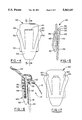
- FIG. 1 is an elevational view of a prior art retaining clip
- FIG. 2 is a cross section along lines 2--2 of FIG. 1;
- FIG. 3 is a cross section of prior art retaining clip installed in a slotted opening of a window opening and bearing a weather sealing strip;
- FIG. 4 is an elevational view of a retaining clip in accordance with the invention.
- FIG. 5 is a cross sectional edge view along lines 5--5 of FIG. 4;
- FIG. 6 is a cross section of the clip of FIGS. 4 and 5 installed in a slotted opening of a window opening and bearing a weather seal;
- FIG. 7 is an elevational view of an alternative retaining clip in accordance with the invention including an additional refinement.
- FIGS. 4 and 5 A retainer clip 40 in accordance with the invention is shown in FIGS. 4 and 5.
- the clip as can be seen in FIG. 5, has a generally sinusoidal-like shape.
- the clip includes a planar central portion 42, an integral downwardly depending arm 44 connected to the central portion by bridge 46, and an integral upwardly extending arm 48 which is connected to the bottom of the central portion by a U-shaped portion 50.
- a pair of integral upstanding wings 52 which are generally coplanar with, and extend upward and outwardly from, the downwardly depending arm 44.
- FIG. 6 wherein a retaining clip in accordance with the principles of the invention is shown inserted into a rectangular slot formed into the lower perimeter or beltline of a window opening in an automotive vehicle door.
- An exposed metal sheet which forms the outer door panel 12 is generally bent or stamped inwardly and then sharply downward to form a narrow inverted U-shaped channel 14 between the outer exposed sheet 12 and an inner downwardly depending leg 16.
- a narrow, substantially horizontal surface at the top of the inverted U-shaped channel 14 defines the lower periphery of the window opening.
- the narrow rectangular hole or slot into which the clip is inserted is annexed so that long sides are aligned with the perimeter of the window opening.
- the entire clip 40 is made of a springy or resilient material, preferably metal such as steel or plastic, which when deformed exerts forces in the opposite direction, tending to return the clip to its original shape.
- the retaining clip 40 is secured to the window opening perimeter by pushing the downwardly depending arm 44 through a narrow, rectangular slot formed in the perimeter.
- the clip is pushed through the slot so that the downwardly depending leg is sandwiched between the central portion 42 and arm 44.
- the narrow sides of the slot slidingly engage and inwardly depress the outward edges of upstanding arms 52 until the clip is fully inserted, whereupon shoulders 53 slide past the edges of the slot allowing the wings 52 to snap outwardly and slide under the edge of the slot to engage lips 54 locking the clip into position.
- the upwardly extending arm 48 is shaped and spaced from the central portion 42 to securely accommodate a beltline sealing strip 34.
- a horizontal groove 56 can be provided on the inner wall of the upwardly extending arm 48 to receive a conforming rib provided on the sealing strip in order to firmly secure the sealing strip to the clip 40.
- a retaining clip 60 generally similar to that of the retaining clip shown in FIGS. 4-6 is provided with a projecting tab 62 which is spaced from lip 54 to enable insertion of a tool such as needle-nose pliers between tab 62 and lip 54.
- the clip can be easily removed applying laterally inward forces on both tabs simultaneously to force wings 52 inward toward the center of the clip and then pulling the clip outward from the slot.
Landscapes
- Engineering & Computer Science (AREA)
- Mechanical Engineering (AREA)
- Seal Device For Vehicle (AREA)
Abstract
Description
Claims (12)
Priority Applications (1)
| Application Number | Priority Date | Filing Date | Title |
|---|---|---|---|
| US08/061,126 US5363537A (en) | 1993-05-13 | 1993-05-13 | Vehicle window weather seal retaining clip |
Applications Claiming Priority (1)
| Application Number | Priority Date | Filing Date | Title |
|---|---|---|---|
| US08/061,126 US5363537A (en) | 1993-05-13 | 1993-05-13 | Vehicle window weather seal retaining clip |
Publications (1)
| Publication Number | Publication Date |
|---|---|
| US5363537A true US5363537A (en) | 1994-11-15 |
Family
ID=22033757
Family Applications (1)
| Application Number | Title | Priority Date | Filing Date |
|---|---|---|---|
| US08/061,126 Expired - Lifetime US5363537A (en) | 1993-05-13 | 1993-05-13 | Vehicle window weather seal retaining clip |
Country Status (1)
| Country | Link |
|---|---|
| US (1) | US5363537A (en) |
Cited By (20)
| Publication number | Priority date | Publication date | Assignee | Title |
|---|---|---|---|---|
| US5544448A (en) * | 1994-12-27 | 1996-08-13 | Ford Motor Company | Structural door belt seal |
| DE19607786A1 (en) * | 1996-03-01 | 1997-09-04 | Nokia Deutschland Gmbh | Connector for detachably mounting component in wall |
| US5799442A (en) * | 1995-11-06 | 1998-09-01 | Toyoda Gosei Co., Ltd. | Door glass weather strip |
| US5913762A (en) * | 1995-12-28 | 1999-06-22 | Tokai Kogyo Co., Ltd. | Weatherstrip for motor vehicle side windows |
| US6223470B1 (en) * | 1999-09-20 | 2001-05-01 | Dura Global Technologies, Inc. | Dropglass window module |
| US6282840B1 (en) * | 1998-12-02 | 2001-09-04 | Gencorp Inc. | Mechanically interlocked weatherstrip |
| US6321490B1 (en) * | 1997-10-01 | 2001-11-27 | Gencorp Inc. | Mechanically interlocked weatherstrip |
| US20030182865A1 (en) * | 2002-03-29 | 2003-10-02 | Nestell David E. | Vertical slider window assembly |
| WO2005056270A1 (en) * | 2003-12-10 | 2005-06-23 | Lee, Hwan-Gil | Method of manufacturing integrated changable insert moldings for automobiles |
| US20050190573A1 (en) * | 2004-02-27 | 2005-09-01 | Schwab Leo F. | Releaseable fastening device |
| US20060260201A1 (en) * | 2005-05-09 | 2006-11-23 | Decoma (Germany) Gmbh | Cover strip |
| US20080110101A1 (en) * | 2006-11-09 | 2008-05-15 | Cooper-Standard Automotive Inc. | Clip-on inner panel seal assembly |
| US20100300002A1 (en) * | 2007-09-11 | 2010-12-02 | Harald Ertl | Trim strip |
| US20130093141A1 (en) * | 2011-09-29 | 2013-04-18 | Hutchinson Sealing Systems | Weather Strip Seal for an Automotive Vehicle, and its Manufacturing Method |
| US20130193711A1 (en) * | 2012-01-30 | 2013-08-01 | GM Global Technology Operations LLC | Vehicle outer belt molding |
| US20130277516A1 (en) * | 2012-04-18 | 2013-10-24 | Magna International Inc. | Retention clip for outer belt weatherstrip |
| US8572897B2 (en) * | 2011-09-14 | 2013-11-05 | Ford Global Technologies, Llc | Weatherstrip cinch clip |
| US9840208B2 (en) * | 2015-10-05 | 2017-12-12 | Hyundai Motor Company | Door outbelt unit for vehicle and vehicle door thererof |
| DE102016012955A1 (en) * | 2016-10-29 | 2018-05-03 | Audi Ag | Spring clip |
| US11186153B2 (en) * | 2017-09-15 | 2021-11-30 | Psa Automobiles Sa | Windows sealing strip with ease of mounting |
Citations (23)
| Publication number | Priority date | Publication date | Assignee | Title |
|---|---|---|---|---|
| US477970A (en) * | 1892-06-28 | Device for carrying keys | ||
| US776549A (en) * | 1904-03-03 | 1904-12-06 | William H Redington | Paper-clip. |
| US788335A (en) * | 1904-07-02 | 1905-04-25 | Frank M Shepard | Garment attachment. |
| US800937A (en) * | 1904-04-19 | 1905-10-03 | Howard Parkes | Belt-holder. |
| US804905A (en) * | 1905-01-04 | 1905-11-21 | Lafayette Weaver Jr | Combination-clasp. |
| US1533702A (en) * | 1923-07-06 | 1925-04-14 | Gerla Bernard | Concealed clasp |
| US2527674A (en) * | 1947-05-03 | 1950-10-31 | Otto H Cold | Clothespin |
| US2542883A (en) * | 1948-08-12 | 1951-02-20 | Tinnerman Products Inc | Fastening device |
| US2585421A (en) * | 1950-03-18 | 1952-02-12 | Estelle T Armand | Book marking device |
| US2818624A (en) * | 1953-02-03 | 1958-01-07 | Fanteux Henri Andre | Hanger |
| US2838056A (en) * | 1954-12-07 | 1958-06-10 | Kertesz Carl | Resilient clip construction |
| US2856666A (en) * | 1957-01-31 | 1958-10-21 | Crothers Evelyn | Garment supporter |
| GB880263A (en) * | 1958-07-21 | 1961-10-18 | Ft Products Ltd | Improvements in and relating to fasteners |
| US3371900A (en) * | 1966-02-14 | 1968-03-05 | Prudential Lighting Corp | Unitary double-detent connector for lighting fixtures |
| US3414944A (en) * | 1967-04-20 | 1968-12-10 | Mildred P. Rabinowitz | Apparatus for matching paired socks and stockings |
| US3575371A (en) * | 1969-02-06 | 1971-04-20 | Paul A Carlstedt | Rope-mounting bracket |
| US3631569A (en) * | 1969-06-23 | 1972-01-04 | Trw Inc | Fastener |
| US3802032A (en) * | 1971-10-04 | 1974-04-09 | R Weed | Invisible tie clip |
| US3908312A (en) * | 1972-12-06 | 1975-09-30 | Renault | Seal and decorative strip assembly for sliding window of vehicle |
| US4023854A (en) * | 1975-09-24 | 1977-05-17 | Nack Jr Frank | Visor |
| US4402118A (en) * | 1981-09-28 | 1983-09-06 | Usm Corporation | Clip for securing a panel to a support |
| US4683622A (en) * | 1986-03-06 | 1987-08-04 | Eaton Corporation | Releasable fastener |
| US4696128A (en) * | 1985-02-05 | 1987-09-29 | Nifco, Inc. | Device for securing molding of automobile door |
-
1993
- 1993-05-13 US US08/061,126 patent/US5363537A/en not_active Expired - Lifetime
Patent Citations (23)
| Publication number | Priority date | Publication date | Assignee | Title |
|---|---|---|---|---|
| US477970A (en) * | 1892-06-28 | Device for carrying keys | ||
| US776549A (en) * | 1904-03-03 | 1904-12-06 | William H Redington | Paper-clip. |
| US800937A (en) * | 1904-04-19 | 1905-10-03 | Howard Parkes | Belt-holder. |
| US788335A (en) * | 1904-07-02 | 1905-04-25 | Frank M Shepard | Garment attachment. |
| US804905A (en) * | 1905-01-04 | 1905-11-21 | Lafayette Weaver Jr | Combination-clasp. |
| US1533702A (en) * | 1923-07-06 | 1925-04-14 | Gerla Bernard | Concealed clasp |
| US2527674A (en) * | 1947-05-03 | 1950-10-31 | Otto H Cold | Clothespin |
| US2542883A (en) * | 1948-08-12 | 1951-02-20 | Tinnerman Products Inc | Fastening device |
| US2585421A (en) * | 1950-03-18 | 1952-02-12 | Estelle T Armand | Book marking device |
| US2818624A (en) * | 1953-02-03 | 1958-01-07 | Fanteux Henri Andre | Hanger |
| US2838056A (en) * | 1954-12-07 | 1958-06-10 | Kertesz Carl | Resilient clip construction |
| US2856666A (en) * | 1957-01-31 | 1958-10-21 | Crothers Evelyn | Garment supporter |
| GB880263A (en) * | 1958-07-21 | 1961-10-18 | Ft Products Ltd | Improvements in and relating to fasteners |
| US3371900A (en) * | 1966-02-14 | 1968-03-05 | Prudential Lighting Corp | Unitary double-detent connector for lighting fixtures |
| US3414944A (en) * | 1967-04-20 | 1968-12-10 | Mildred P. Rabinowitz | Apparatus for matching paired socks and stockings |
| US3575371A (en) * | 1969-02-06 | 1971-04-20 | Paul A Carlstedt | Rope-mounting bracket |
| US3631569A (en) * | 1969-06-23 | 1972-01-04 | Trw Inc | Fastener |
| US3802032A (en) * | 1971-10-04 | 1974-04-09 | R Weed | Invisible tie clip |
| US3908312A (en) * | 1972-12-06 | 1975-09-30 | Renault | Seal and decorative strip assembly for sliding window of vehicle |
| US4023854A (en) * | 1975-09-24 | 1977-05-17 | Nack Jr Frank | Visor |
| US4402118A (en) * | 1981-09-28 | 1983-09-06 | Usm Corporation | Clip for securing a panel to a support |
| US4696128A (en) * | 1985-02-05 | 1987-09-29 | Nifco, Inc. | Device for securing molding of automobile door |
| US4683622A (en) * | 1986-03-06 | 1987-08-04 | Eaton Corporation | Releasable fastener |
Cited By (28)
| Publication number | Priority date | Publication date | Assignee | Title |
|---|---|---|---|---|
| US5544448A (en) * | 1994-12-27 | 1996-08-13 | Ford Motor Company | Structural door belt seal |
| US5799442A (en) * | 1995-11-06 | 1998-09-01 | Toyoda Gosei Co., Ltd. | Door glass weather strip |
| US5913762A (en) * | 1995-12-28 | 1999-06-22 | Tokai Kogyo Co., Ltd. | Weatherstrip for motor vehicle side windows |
| DE19607786C2 (en) * | 1996-03-01 | 2002-11-21 | Harman Audio Electronic Sys | connecting element |
| DE19607786A1 (en) * | 1996-03-01 | 1997-09-04 | Nokia Deutschland Gmbh | Connector for detachably mounting component in wall |
| US6321490B1 (en) * | 1997-10-01 | 2001-11-27 | Gencorp Inc. | Mechanically interlocked weatherstrip |
| US6282840B1 (en) * | 1998-12-02 | 2001-09-04 | Gencorp Inc. | Mechanically interlocked weatherstrip |
| US6223470B1 (en) * | 1999-09-20 | 2001-05-01 | Dura Global Technologies, Inc. | Dropglass window module |
| US20030182865A1 (en) * | 2002-03-29 | 2003-10-02 | Nestell David E. | Vertical slider window assembly |
| US6691464B2 (en) | 2002-03-29 | 2004-02-17 | Donnelly Corporation | Vertical slider window assembly |
| WO2005056270A1 (en) * | 2003-12-10 | 2005-06-23 | Lee, Hwan-Gil | Method of manufacturing integrated changable insert moldings for automobiles |
| US7404688B2 (en) * | 2004-02-27 | 2008-07-29 | General Motors Corporation | Releasable fastening device |
| US20050190573A1 (en) * | 2004-02-27 | 2005-09-01 | Schwab Leo F. | Releaseable fastening device |
| US20070284897A1 (en) * | 2004-02-27 | 2007-12-13 | General Motors Corporation | Releasable Fastening Device |
| US20060260201A1 (en) * | 2005-05-09 | 2006-11-23 | Decoma (Germany) Gmbh | Cover strip |
| US20080110101A1 (en) * | 2006-11-09 | 2008-05-15 | Cooper-Standard Automotive Inc. | Clip-on inner panel seal assembly |
| US7950186B2 (en) * | 2006-11-09 | 2011-05-31 | Cooper-Standard Automotive Inc. | Clip-on inner panel seal assembly |
| US20100300002A1 (en) * | 2007-09-11 | 2010-12-02 | Harald Ertl | Trim strip |
| US8656644B2 (en) * | 2007-09-11 | 2014-02-25 | Cadea Gesellschaft Fur Anwendung Und Realisierung Computerunterstutzter Systeme Mbh | Trim strip |
| US8572897B2 (en) * | 2011-09-14 | 2013-11-05 | Ford Global Technologies, Llc | Weatherstrip cinch clip |
| US20130093141A1 (en) * | 2011-09-29 | 2013-04-18 | Hutchinson Sealing Systems | Weather Strip Seal for an Automotive Vehicle, and its Manufacturing Method |
| US20130193711A1 (en) * | 2012-01-30 | 2013-08-01 | GM Global Technology Operations LLC | Vehicle outer belt molding |
| US8789313B2 (en) * | 2012-01-30 | 2014-07-29 | GM Global Technology Operations LLC | Vehicle outer belt molding |
| US20130277516A1 (en) * | 2012-04-18 | 2013-10-24 | Magna International Inc. | Retention clip for outer belt weatherstrip |
| US9003709B2 (en) * | 2012-04-18 | 2015-04-14 | GM Global Technology Operations LLC | Retention clip for outer belt weatherstrip |
| US9840208B2 (en) * | 2015-10-05 | 2017-12-12 | Hyundai Motor Company | Door outbelt unit for vehicle and vehicle door thererof |
| DE102016012955A1 (en) * | 2016-10-29 | 2018-05-03 | Audi Ag | Spring clip |
| US11186153B2 (en) * | 2017-09-15 | 2021-11-30 | Psa Automobiles Sa | Windows sealing strip with ease of mounting |
Similar Documents
| Publication | Publication Date | Title |
|---|---|---|
| US5363537A (en) | Vehicle window weather seal retaining clip | |
| JPH0231603Y2 (en) | ||
| AU739508B2 (en) | Clip for mounting objects on a wall stud | |
| US6665914B2 (en) | Clip | |
| KR101757243B1 (en) | Method for mounting a part on a profiled bead, intermediate attachment device for attaching a part on a profiled bead, glass sheet, and use of said device | |
| US8038167B2 (en) | Two stage high retention fastener | |
| US7226260B2 (en) | Sheet metal fastening clip | |
| US7337505B1 (en) | Panel fastener | |
| US4866895A (en) | Glass to sash channel attachment | |
| US8882421B2 (en) | Fastening structure for part and clip used therein | |
| US20200339044A1 (en) | Arrowhead Fastener Clip with Barbs | |
| CN217002565U (en) | Fastening clip assembly with expandable cap | |
| US6155010A (en) | Window grill clips | |
| US20160123053A1 (en) | Baggage door | |
| EP3779215A1 (en) | Arrowhead fastener clip with barbs | |
| EP3696428A1 (en) | Fastener clip with stabilizing shoulder tabs | |
| US2913952A (en) | Piercing fastener with deformable head and expanding legs | |
| JP2000142102A (en) | Method, device, and structure for mounting of molding | |
| CN212140146U (en) | Elastic buckle plate and magnetic door curtain fixedly installed through elastic buckle plate | |
| US20170122349A1 (en) | Baggage door | |
| US4472915A (en) | Provision of anchorage points adjacent beading mounted windows | |
| JPS6135444Y2 (en) | ||
| JP2002052936A (en) | Door inner seal mounting structure | |
| CA2147237A1 (en) | Spring snap clip | |
| JPS6332004Y2 (en) |
Legal Events
| Date | Code | Title | Description |
|---|---|---|---|
| AS | Assignment |
Owner name: GENCORP INC., OHIO Free format text: ASSIGNMENT OF ASSIGNORS INTEREST;ASSIGNORS:SCHNEIDER, STEVEN E.;ROGERS, RICK L.;GARDNER, ERIC E.;REEL/FRAME:006558/0940;SIGNING DATES FROM 19930421 TO 19930430 |
|
| STPP | Information on status: patent application and granting procedure in general |
Free format text: APPLICATION UNDERGOING PREEXAM PROCESSING |
|
| FPAY | Fee payment |
Year of fee payment: 4 |
|
| FPAY | Fee payment |
Year of fee payment: 8 |
|
| AS | Assignment |
Owner name: DEUTSCHE BANK TRUST COMPANY AMERICAS, (FORMERLY KN Free format text: ASSIGNMENT OF SECURITY INTEREST IN US TRADEMARKS AND PATENTS;ASSIGNOR:GENCORP INC.;REEL/FRAME:013386/0934 Effective date: 20021002 |
|
| AS | Assignment |
Owner name: GDX NORTH AMERICA INC., NEW YORK Free format text: ASSIGNMENT OF ASSIGNORS INTEREST;ASSIGNOR:GENCORP, INC.;REEL/FRAME:015139/0772 Effective date: 20040831 |
|
| FPAY | Fee payment |
Year of fee payment: 12 |
|
| AS | Assignment |
Owner name: KOMAGATA HOLDING B.V., NETHERLANDS Free format text: SECURITY AGREEMENT;ASSIGNOR:GDX NORTH AMERICA, INC.;REEL/FRAME:018837/0277 Effective date: 20070118 |
|
| AS | Assignment |
Owner name: MAPS HOLDINGS, INC., MICHIGAN Free format text: ASSIGNMENT OF ASSIGNORS INTEREST;ASSIGNOR:KOMAGATA HOLDING B.V.;REEL/FRAME:021590/0580 Effective date: 20071214 |
|
| AS | Assignment |
Owner name: HENNIGES AUTOMOTIVE HOLDINGS, INC., MICHIGAN Free format text: CHANGE OF NAME;ASSIGNOR:MAPS HOLDINGS, INC.;REEL/FRAME:021603/0275 Effective date: 20080114 |
|
| AS | Assignment |
Owner name: HENNIGES AUTOMOTIVE SEALING SYSTEMS NORTH AMERICA, Free format text: CHANGE OF NAME;ASSIGNOR:GDX NORTH AMERICA INC.;REEL/FRAME:021651/0352 Effective date: 20080114 |
|
| AS | Assignment |
Owner name: HENNIGES AUTOMOTIVE SEALING SYSTEMS NORTH AMERICA, Free format text: RELEASE BY SECURED PARTY;ASSIGNOR:HENNIGES AUTOMOTIVE HOLDINGS, INC.;REEL/FRAME:021731/0533 Effective date: 20081024 |
|
| AS | Assignment |
Owner name: BANK OF AMERICA, N.A., NORTH CAROLINA Free format text: SECURITY AGREEMENT;ASSIGNOR:HENNIGES AUTOMOTIVE SEALING SYSTEMS NORTH AMERICA, INC.;REEL/FRAME:022015/0801 Effective date: 20081031 |
|
| AS | Assignment |
Owner name: HENNIGES AUTOMOTIVE SEALING SYSTEMS NORTH AMERICA, Free format text: RELEASE BY SECURED PARTY;ASSIGNOR:BANK OF AMERICA, N.A.;REEL/FRAME:025464/0317 Effective date: 20101130 |
|
| AS | Assignment |
Owner name: PNC BANK, NATIONAL ASSOCIATION, AS ADMINISTRATIVE Free format text: SECURITY AGREEMENT;ASSIGNORS:HENNIGES AUTOMOTIVE HOLDINGS, INC.;SCHLEGEL CORPORATION;HENNIGES AUTOMOTIVE SEALING SYSTEMS NORTH AMERICA, INC.;REEL/FRAME:025494/0130 Effective date: 20101130 |
|
| AS | Assignment |
Owner name: PNC BANK, NATIONAL ASSOCIATION, PENNSYLVANIA Free format text: AMENDED AND RESTATED PATENT, TRADEMARK AND COPYRIGHT SECURITY AGREEMENT;ASSIGNORS:HENNIGES AUTOMOTIVE HOLDINGS, INC.;HENNIGES AUTOMOTIVE SEALING SYSTEMS NORTH AMERICA, INC.;SCHLEGEL CORPORATION;REEL/FRAME:027755/0337 Effective date: 20120224 |
|
| AS | Assignment |
Owner name: HENNIGES AUTOMOTIVE HOLDINGS, INC., MICHIGAN Free format text: RELEASE BY SECURED PARTY;ASSIGNOR:PNC BANK NATIONAL ASSOCIATION;REEL/FRAME:038139/0922 Effective date: 20160322 Owner name: SCHLEGEL CORPORATION, MICHIGAN Free format text: RELEASE BY SECURED PARTY;ASSIGNOR:PNC BANK NATIONAL ASSOCIATION;REEL/FRAME:038139/0922 Effective date: 20160322 Owner name: HENNIGES AUTOMOTIVE SEALING SYSTEMS NORTH AMERICA, Free format text: RELEASE BY SECURED PARTY;ASSIGNOR:PNC BANK NATIONAL ASSOCIATION;REEL/FRAME:038139/0922 Effective date: 20160322 |