US5313582A - Method and apparatus for buffering data within stations of a communication network - Google Patents
Method and apparatus for buffering data within stations of a communication network Download PDFInfo
- Publication number
- US5313582A US5313582A US07/693,637 US69363791A US5313582A US 5313582 A US5313582 A US 5313582A US 69363791 A US69363791 A US 69363791A US 5313582 A US5313582 A US 5313582A
- Authority
- US
- United States
- Prior art keywords
- data
- packet
- communication controller
- packet number
- data packet
- Prior art date
- Legal status (The legal status is an assumption and is not a legal conclusion. Google has not performed a legal analysis and makes no representation as to the accuracy of the status listed.)
- Expired - Lifetime
Links
Images


Classifications
-
- G—PHYSICS
- G06—COMPUTING; CALCULATING OR COUNTING
- G06F—ELECTRIC DIGITAL DATA PROCESSING
- G06F5/00—Methods or arrangements for data conversion without changing the order or content of the data handled
- G06F5/06—Methods or arrangements for data conversion without changing the order or content of the data handled for changing the speed of data flow, i.e. speed regularising or timing, e.g. delay lines, FIFO buffers; over- or underrun control therefor
-
- G—PHYSICS
- G06—COMPUTING; CALCULATING OR COUNTING
- G06F—ELECTRIC DIGITAL DATA PROCESSING
- G06F12/00—Accessing, addressing or allocating within memory systems or architectures
- G06F12/02—Addressing or allocation; Relocation
- G06F12/0223—User address space allocation, e.g. contiguous or non contiguous base addressing
-
- H—ELECTRICITY
- H04—ELECTRIC COMMUNICATION TECHNIQUE
- H04L—TRANSMISSION OF DIGITAL INFORMATION, e.g. TELEGRAPHIC COMMUNICATION
- H04L49/00—Packet switching elements
- H04L49/90—Buffering arrangements
-
- H—ELECTRICITY
- H04—ELECTRIC COMMUNICATION TECHNIQUE
- H04L—TRANSMISSION OF DIGITAL INFORMATION, e.g. TELEGRAPHIC COMMUNICATION
- H04L9/00—Cryptographic mechanisms or cryptographic arrangements for secret or secure communications; Network security protocols
- H04L9/40—Network security protocols
Definitions
- the present invention generally concerns a method and apparatus for buffering data within stations of a communications network, and more particularly to such a method and apparatus which enables each station to receive and transmit consecutive data packets in a manner less sensitive to processor interrupt latency, while optimally using memory and minimizing host processor overhead and necessity of copying data between structures.
- Local-area networks are communication systems for enabling data-processing devices, such as computer workstations, to communicate with each other through a communication (e.g. transmission) media.
- Data-processing devices in such networks are typically referred to as nodes or stations, and many such stations are likely to be relatively autonomous, requiring communication with other stations only occasionally. Other stations may require more frequent communication, and the amount of communication required by a particular station can vary from time to time.
- stations can be easily added to, removed from, and moved from place to place within the network. While there are numerous local area networks presently known, they can be classified into two general types.
- the first type of network is referred to as a "centralized network” which is characterized by the requirement of a centralized network controller which implements the network protocol.
- the second type of local area network is referred to as a "distributed network” which does not require a centralized network controller, and instead provides each station within the network with a communication controller having a medium access control (MAC) unit that locally implements the network protocol within each communication controller.
- MAC medium access control
- packet switching is a technique commonly employed to dynamically allocate the communication resources of the network among multiple communicating stations.
- messages to be communicated between stations are partitioned (by the transmitting station's processor) into packets, having a fixed maximum size.
- the packets are then ascribed a station (i.e. source) identifier.
- the packets are then placed on the communication medium by the station's communication controller. Such packets are then sensed and selectively processed by the communication controller of the destination station in the network.
- Any packet from one station to another station contains various fields of information specified in accordance with a predetermined network protocol.
- the information typically includes the identity of the source station, the identity of the destination station, and various other information concerning the characteristics of the packet.
- a number of different types of packets may appear on the communication medium in accordance with the network protocol. Typically, these packets relate to either communication control or data-transfer functions.
- FIGS. 1 through 3 To more fully appreciate the problems associated with conventional communication controllers used in the stations of distributed local-area-networks, reference is made to FIGS. 1 through 3.
- a distributed local area-network 100 comprising a plurality of stations (i.e. nodes 102A through 102M) which are operably associated to a communication medium 103, such as a cable.
- each station is shown to generally comprise a host processor (e.g., CPU) 104, a program memory 105, a system memory 106, a communication controller 107, a system bus 108, and a communication medium interface unit 109.
- the processor, program memory and system memory are each associated with a system bus 108, and the system bus, in turn, is interfaced with communication controller 107, as shown.
- the communication controller is interfaced with the communication medium by way of the communication medium interface unit.
- the communication medium interface unit is suitably adapted for the particular characteristics of the communication medium being employed in the network.
- communication controllers and LAN controllers in particular, are usually integrated into a system architecture and software environment by providing the means for supporting two independent data queues in software: a transmit queue and a receive queue.
- Each queue is associated with a process, namely, the transmit process and the receive process of the low-level software communications driver.
- the transmit queue holds the elements that the software intends to transmit.
- these elements are usually data packets that include a block of data to be transmitted and some associated information like the destination for the block of data.
- the receive queue hold the elements that the station has received, again usually packets with a block of data and associated information such as the sender of the data block.
- Elements are added to the transmit queue by the software driver whenever it needs to transmit information. Elements are removed from the transmit queue after successful transmission is assumed. Removal of the elements can be done either by the low-level software driver or by the communication controller. Elements are added to the receive queue by the communication controller whenever a relevant packet is received, and are removed by the low-level software driver upon processing the packet.
- the transmit and receive queues are managed by software in system memory, and eventually meet the communication controller.
- the interface between the queues and the communications controller determines the behavior of the queues during the addition of receive elements and removal of transmit elements.
- some prior art communication controllers are as simple as a single element queue, in which the controller can handle only one transmit and one receive element at a time and the host processor must be involved in feeding the queue.
- Representative of this type of prior art is the 90C65 Communication Controller from Standard Microsystems Corporation of Hauppauge, N.Y.
- a major shortcoming of this type of communication controller is that it is highly sensitive to interrupt latency of the host processor.
- An alternative type of prior art communication controller employs queues for transmit and receive commands while storing corresponding data packets in a randomly accessible memory associated with the communication controller.
- Representative of this type of prior art is the 90C66 Communication Controller from Standard Microsystems.
- this communication controller design is substantially less sensitive to interrupt latency in comparison with the above-described communication controller.
- the prior art has sought to extend the transmit and receive data queues into the communication controller by simulating transmit and receive data queues in the data packet buffer memory of the communication controller.
- this generalized memory management technique there have been several different approaches to implementing this generalized memory management technique.
- many transmit and receive data elements can be managed as a "ring buffer,” in which data packet buffer memory is configured as a number of memory elements which can be sequentially allocated and accessed.
- Prior art representative of this approach includes the 8390 NIC Communication Controller from National Semiconductor Corporation, and the Etherstar® Ethernet Communications Controller from Fujitsu Corporation.
- Significant shortcomings and drawbacks of the "ring buffer" communication controller are inefficient memory utilization, high CPU overhead and memory fragmentation.
- communication controller 107' comprises a CPU interface unit 110, a link-list processor 111, a medium access control (MAC) unit 112, and a MAC interface unit 114.
- MAC medium access control
- MAC medium access control
- MAC medium access control
- MAC MAC interface unit
- RAM data packet buffer memory
- the CPU interface unit interfaces system bus 108 with the link-list processor and the data packet memory buffer by way of an address and data bus, as shown.
- the MAC interface unit interfaces the medium access control unit 109 with the link-list processor and the data packet buffer memory, also by way of an address and data bus, as shown.
- Prior art representative of the above type device includes the 82586 and 82596 Communication Controllers from Intel Corporation.
- the link-list communication controller In order for the link-list communication controller to find the memory storage location where a packet begins, as well as the storage locations where each one of the buffers (comprising a packet) begins, the software driver must perform a number of computations. Such packet address computations and the necessity of managing numerous address pointers create high software overhead. Also with this prior art approach, memory utilization is inefficient owing to the fact that pointers and link-list structures utilize memory and due to the fact that link-lists use fixed memory allocations between transmit and receive queues.
- CPU host processor
- a further object of the present invention is to provide such a method and apparatus of buffering data packets in a communication controller in which data packet buffer memory appears to the host processor as two linearly mapped fixed-length regions of memory space for the transmit and receive queues, respectively, while in actuality, the size of the buffer memory is much greater, and the data page storage locations for each data packet are arbitrarily assigned, need not be contiguous, and number thereof is dependent on the actual length of the data packet to be stored.
- a further object of the present invention is to provide such method and apparatus in the form of a communication controller, in which buffer memory space between transmit and receive data packet queues is shared and dynamically allocated to optimize memory utilization.
- a further object of the present invention is to provide such a communication controller, in which dynamic allocation of buffer memory is transparent to the host processor and the medium access control unit of the communication controller.
- a method of buffering data packets in a communication controller is provided.
- the communication controller is interfaced with a processor for processing data packets, and includes a control unit for accessing a communication medium.
- the method comprises providing a data packet storage means which is operably associated with the communication controller.
- the data storage means includes a plurality of data page storage locations.
- a packet number is assigned to a data packet to be stored in one or more data page storage locations.
- the data packet is stored in one or more of the data page storage locations. These one or more data page storage locations are specified by the corresponding packet number assigned to the data packet.
- the packet number assigned to the data packet is stored in a packet number queue which is maintained in the communication controller.
- the packet number queue is capable of storing one or more of the packet numbers, with each packet number corresponding to one stored data packet. Then, sometime later, the packet number is retrieved from the packet number queue and used to access the data packet from the one or more data page storage locations specified by the retrieved packet number.
- the packet number queue has a depth sufficient to queue a plurality of packet numbers, each of which corresponds to a data packet stored in data packet storage means. For each data packet to be stored (i.e. loaded) and subsequently retrieved (i.e. unloaded) the above process is carried out, although not necessarily in sequential order.
- the data storage locations and packet numbers are dynamically allocated.
- the number of data page storage locations required to store each data packet is first determined.
- the required number of free data page storage locations are then allocated for storing the data packet.
- the unique packet number is assigned to each allocated data page storage location.
- linear-to-physical address conversion is employed to create memory access windows in the data packet storage means. In this way, writing into or reading from the data packet storage means appears as if accessing a fixed memory storage space, when in fact, the actual physical storage locations being accessed are situated elsewhere in buffer memory, unbeknownst to both the processor and the medium access control unit.
- a pair of packet number queues are independently maintained for packet numbers assigned to transmit and receive data packets, respectively.
- variable length transmit and receive data packet queues can be effectively maintained in the data packet storage buffer. Consequently, memory utilization is according to first-come-first-serve principles.
- a high performance communication controller is provided.
- the communication controller is interfaceable with a host processor and is operably associable with a data packet storage means including a plurality of data page storage locations for storing one or more data packets.
- the communication controller comprises a control unit, a memory management means, data packet transfer means, a packet number queue, and packet number transfer means.
- the control unit is for accessing a communication medium.
- the memory management means manages the data packet storage means by assigning a packet number to each data packet to be stored therein and by allocating one or more of the data page storage locations for storing each said data packet.
- the packet numbers are accessible to one or both of the processor and the control unit.
- the data packet transfer means is provided for transferring one or more data packets between the processor and the data packet storage means. Also, the data packet transfer means facilitates transferring one or more data packets between the data packet storage means and the control unit.
- the packet number queue facilitates storage of one or more packet numbers, each of which corresponds to a stored data packet.
- the packet number transfer means facilitates transferring packet numbers between the packet number queue and at least one of the control unit and the processor, and between the memory management unit and at least one of the control unit and the processor.
- packet number queues are provided for both transmit and receive data packets, and packet numbers are assigned by the memory management unit.
- the memory management means provides memory access windows into the data packet storage means so that the actual physical storage locations are transparent to the processor and the control unit. Such memory access windows are realized by providing the memory management means with a linear-to-physical address conversion unit that maps linear addresses into physical addresses.
- a data communication controller having a mechanism for automatically generating transmit interrupts to the host processor upon the completion of any preselected number of data packet transmissions determined by the host processor.
- the mechanism utilizes a transmit packet number queue structure having first and second storage locations for removing packet numbers.
- the mechanism is adapted to automatically generate a transmit interrupt upon transmission of the data packets associated with each particular record or packet sequence transmitted by the host processor.
- FIG. 1 is a schematic representation of a local area network system permitting a plurality of stations to access to a shared communication medium allocated in accordance with a network protocol;
- FIG. 2 is a block functional diagram of a prior art station within the local area network of FIG. 1, showing the major components of the station;
- FIG. 3 is a block functional diagram of a prior art station illustrated in FIG. 2, showing functional subunits of a link-list communication controller incorporated therein.
- FIG. 4 is a high-level schematic representation of a communication controller constructed in accordance with the present invention, illustrating the basic parameters utilized by the host processor (i.e. CPU) and the medium access control unit during data-communication operations;
- the host processor i.e. CPU
- the medium access control unit during data-communication operations
- FIG. 5 is a high-level schematic representation of the communication controller illustrated in FIG. 4, with the addition of linear address generation capabilities at the sides of the host processor and the medium access control unit, in order to facilitate sequential data-byte transfer in the preferred embodiment of the present invention;
- FIG. 5A is a high-level schematic representative of the communication controller of the present invention, which as seen by the host processor and the medium access control unit, has a memory access window for transfer of data packets having up to a maximum number of data bytes, the addresses of which are linearly ordered as shown;
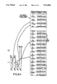
- FIGS. 6 and 6A taken together, provides a schematic representation of a data buffering method according to a first embodiment of the present invention, illustrating data packet queueing in system memory, packet number assignment, linear address generation for data packets to be transferred to data packet buffer memory, and linear-to-physical address conversion for storage of the data packets;
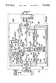
- FIG. 7 is a block functional diagram of the communication controller according to the first embodiment of the present invention, showing its subcomponents integrated together and interfaced between the host processor and the medium access control unit;
- FIG. 7A is a block functional diagram of the memory management unit of the communication controller of FIG. 7;
- FIG. 7B is a schematic representation of an address conversion table implemented in the address conversion unit shown in FIG. 7A;
- FIG. 7C is a schematic representation of a packet number and physical page allocation table implemented in the page allocation and management unit shown in FIG. 7A;
- FIG. 8A is a schematic representation of the data packet storage format employed in the data packet buffer memory of the communication controller of the illustrated embodiment
- FIG. 8B is a schematic representation of the data packet transmission format employed by the communication controller of the illustrated embodiment during transmission of data packets over the network communication medium;
- FIGS. 9 and 9A together show a schematic representation of a method of data packet buffering according to a second embodiment of the present invention, illustrating data packet queuing in system memory, packet number assignment, linear address generation for data packets to be transferred to external buffer memory, and linear-to-physical address conversion for storage of the data packets;
- FIG. 10 is a block functional diagram of the communication controller according to the second embodiment of the present invention, showing its subcomponents interfaced between the host processor and the medium access control unit, with the external buffer memory interfaced with the memory management unit and other subcomponents;
- FIG. 10A is a block functional diagram of the memory management unit of the communication controller of FIG. 10;
- FIG. 10B is a schematic representation of an address conversion table implemented in the address conversion unit shown on FIG. 10A;
- FIG. 10C is a schematic representation of a packet number and page allocation table implemented in the page allocation and management unit shown in FIG. 10A;
- FIG. 11 is a block functional diagram of the communication controller according to the third embodiment of the present invention, showing transmit and receive packet number queues in operable association with the CPU interface unit so as to automatically generate transmit interrupts to the host processor in a flexible manner;
- FIG. 11A is a block functional diagram of the transmit and receive packet number queues and CPU interface unit of one embodiment of the communication controller of FIG. 11;
- FIG. 11B is a block functional diagram of the transmit and receive packet number queues and CPU interface unit of an alternative embodiment of the communication controller of FIG. 11;
- FIG. 12A is a flow control diagram illustrating operations undertaken by the host processor during loading of a transmit data packet into the data packet buffer memory of the communication controllers of FIGS. 7, 10 and 11;
- FIG. 12B is a flow control diagram illustrating operations undertaken by the medium access control unit during unloading of a transmit data packet from the data packet buffer memory of the communication controllers of FIGS. 7, 10 and 11;
- FIG. 12C is a flow control diagram illustrating optional operations undertaken by the host processor, upon receipt of an interrupt, in order to determine status of a particular transmit data packet;
- FIG. 13A is a flow control diagram illustrating operations undertaken by the medium access control unit during loading of an incoming receive data packet into the data packet buffer memory of the communication controller of FIG. 7;
- FIG. 13B is a flow control diagram illustrating operations undertaken by the host processor during unloading of a receive data packet from the data packet buffer memory of the communication controller of FIGS. 7.
- the method and apparatus for buffering data packets in accordance with the present invention is schematically illustrated in connection with a host processor (i.e. CPU) 1 and the medium access control (MAC) unit 2 of a communication controller 3.
- a host processor i.e. CPU
- the medium access control unit typically comprises a microsequencer running a microprogram or state machine (i.e., an algorithm) which effectuates the network protocol and ultimately, the communication controller's access to the communication medium.
- a microprogram or state machine i.e., an algorithm
- each medium access control unit in each station communication controller must perform the same algorithm.
- Processor "interrupts" provided by the communication controller are the basic scheduling events upon which the low-level driver manages the flow of data packets between transmit and receive queues, and the communication controller.
- the communication controller of the present invention generally comprises data packet buffer memory 6 for queuing transmit and receive data packets; a buffer memory management unit (i.e. facility) 7 which as illustrated, includes an address conversion (i.e., mapping) unit 8; and transmit and receive packet number queues 9 and 10 for queuing packet numbers assigned to transmit and receive data packets, respectively.
- Address conversion unit 8 is operably associated with buffer memory 6 and in general accepts as input packet numbers N Ti and N Rj and produces a set of physical addresses defining available storage space (i.e. locations) within buffer memory 6.
- packet number transfer means 11 On the host processor side, packet number transfer means 11 is provided for transferring packet numbers from the host processor to transmit packet number queue 9, as well as from the host processor to address conversion unit 8. Packet number transfer means 12 is also provided for transferring packet numbers from receive packet number queue 10 to the host processor, as well as from the host processor to address conversion unit 8.
- packet number transfer means 13 On the medium access control unit side, packet number transfer means 13 is provided for transferring packet numbers from transmit packet number queue 9 to the medium access control unit, as well as from the medium access control unit to address conversion unit 8. Packet number transfer means 14 is also provided for transferring packet numbers from medium access control unit to address conversion unit 8, as well as from the medium access control unit to receive packet number queue 10.
- data packet transfer means 15 In order to transfer data packets between transmit packet queue 4 and buffer memory 6, and between buffer memory 6 and the medium access control unit, data packet transfer means 15 is also provided. Also, to transfer data packets between receive packet queue 5 and buffer memory 6, and between buffer memory 6 and the medium access control unit, data packet transfer means 16 is provided. Typically, data packet transfer means 15 and 16 are in the form of data buses, well known in the art.
- memory management unit 7 determines which data storage locations are available in buffer memory and dynamically allocates an arbitrary yet sufficient number of those storage locations to an available packet number, so as to be able to store the corresponding data packet.
- the i-th transmit data packet D Ti in transmit queue 4 is stored in buffer memory 6 by issuing a packet number N Ti to the address conversion unit of the memory management unit.
- Address conversion unit 8 then generates a set of physical addresses A Ti ' which provide access to corresponding storage locations which have been allocated in buffer memory.
- the host processor copies transmit data packet D Ti from transmit queue 4 into the physical storage locations specified by the assigned packet number through the address conversion process.
- packet number N Ti is inserted into transmit packet number queue 9 for subsequent use by the medium access control unit, during packet unloading operations.
- request transfer means 18 To transfer each memory storage request R Ti from the host processor to packet number assignment unit 17, request transfer means 18 is provided. To transfer each assigned packet number N Ti from packet number assignment unit 17 to the host processor, packet number transfer means 19 is provided. Similarly, to transfer each memory request R Rj from the medium access control unit to packet number assignment unit 17, request transfer means 20 is provided, whereas packet number transfer means 21 is provided for transferring each assigned packet number N Rj to the medium access control unit.
- transmit packet number queue 9 will contain a number of packet numbers arranged in a sequential order, such that the first packet number inserted into the queue is the first one to be removed from the queue.
- Each transmit data packet D Ti corresponding to packet number N Ti in the transmit packet number queue is stored in buffer memory 6 in a manner and location completely transparent to the host processor and the medium access control unit.
- the assigned packet numbers in the transmit packet number queue 4 retain all queue information relating to the transmit data packets stored in buffer memory 6.
- the following process is carried out by the medium access control unit, in order to unload from buffer memory 6, the transmit data packet which corresponds to the packet number first to be removed from transmit packet number queue 4.
- the medium access control unit first reads out the i-th data packet number N Ti from the removal location of transmit packet number queue 4. This retrieved packet number is then provided to address conversion unit 8 which generates physical addresses A Ti ' that specify the physical storage locations in which the data bytes of the corresponding data packet D Ti are stored. From these accessed storage locations in buffer memory, the data bytes comprising the transmit data packet D Ti are read out by the medium access control unit and subsequently placed on the communication medium 103. After transmission of data packet D Ti , the medium access control unit can write transmit status data into storage locations associated with the physical storage locations from which data packet D Ti was read out. After transmit status data is written into buffer memory 6, an interrupt to the host processor is generated.
- the host processor maintaining a software queue of assigned packet numbers N Ti , gains access to transmit status data in these physical storage locations, by selecting packet number N Ti from the removal location in the software queue. The selected packet number N Ti is then converted into the allocated physical addresses A Ti ' by the address conversion unit. After transmit status data is read and utilized by the host processor, the host processor issues a release command F(N Ti ) to packet number assignment unit 7, in order to release the storage locations in buffer memory 6 that have been allocated to packet number N Ti . In this way, these released storage locations will be free for future allocation to either transmit or receive data packets.
- the communication controller of the present invention operates much in the same way for loading and unloading of receive data packets D Rj .
- the medium access control unit issues a request R Rj to the memory management unit for allocation of a number of storage locations in buffer memory 6, sufficient to store the j-th incoming receive data packet, D Rj .
- a packet number N Rj is assigned to the j-th receive data packet, D Rj and then provided to the medium access control unit.
- the medium access control unit issues assigned packet number N Rj to the address conversion unit of the memory management unit, which generates a set of physical addresses A Rj that specify and provide access to storage locations in buffer memory 6, for storing receive data packet D Rj which corresponds to packet number N Rj .
- the j-th receive data packet D Rj is read from the medium access control unit into the allocated storage locations. After loading receive data packet D Rj into buffer memory, corresponding packet number N Rj is placed into the insertion location of receive packet number queue 10 of the communication controller. Receive status data concerning the receive data packet D Rj , can be written into one or more of those storage locations which have been allocated to receive packet number N Rj . The nature of such receive status data can relate to the integrity or the type of data packet just reviewed. Subsequently, an interrupt to the host processor will be generated indicating that unloading of a receive data packet can take place when desired by the host processor. Prior to the packet unloading operation, however, the host processor can read receive status data stored in buffer memory, in a manner similar to transmit status data storage and retrieval discussed above.
- receive packet number queue 10 After loading a number of receive data packets D Rj into buffer memory 6 as described above, receive packet number queue 10 will contain a number of packet numbers, also arranged in a sequential order such that the first packet number into the queue is the first one to be received from the queue. Also, each receive data packet D Rj , corresponding to packet number N Rj in receive packet number queue 10, is stored in buffer memory 6 along with transmit data packets, and in a manner and location completely transparent to the medium access control unit and the host processor. As with the stored transmit data packets, the assigned packet numbers in receive packet number queue 10 retain all queue information relating to the receive data packets stored in buffer memory.
- the following process is carried out by the host processor, in order to unload from buffer memory 6, the receive data packet which corresponds to the packet number first to be removed from transmit packet number queue 10.
- the host processor first reads out the j-th data packet number N Rj from the removal location of receive packet number queue 10. This retrieved packet number N Rj is then provided to address conversion unit 8, which generates the physical addresses A Rj ' that specify the physical storage locations, in which the data and status bytes of the corresponding data packet D Rj are stored. Upon generating an interrupt, receive status bytes are read out by the host processor from storage locations in buffer memory 6. After checking the integrity of the received data packets D Rj and transferring the receive data packet from buffer memory to receive data packet queue 5, the host processor issues a release command F(N Rj ) to packet number assignment unit 17 in order to release the storage locations in buffer memory 6 that have been allocated to packet number N Rj . In this way, these released storage locations will be free for future allocation to transmit or receive data packets.
- a significant feature of the present invention described above is that all during the loading and unloading operations of data packets, the physical storage locations in buffer memory 6 are transparent to both the host processor and the medium access control unit.
- the host processor and medium access control unit acquire necessary access to buffer memory 6 by providing a packet number to the memory management unit, and then transferring the corresponding data packet into or out of the buffer memory, as desired. Conversion of packet numbers into physical addresses and determination and allocation of free storage locations within buffer memory, occurs completely transparent to the host processor and the medium access control unit.
- this reduces substantially the overhead of the software-based low-level drivers, as well as the algorithm-based medium access control unit.
- the above-described method and apparatus for buffering data packets within a communication controller has assumed that the host processor and medium access control unit are each capable of transferring, as complete elements, data packets (D Ti and D Rj ) to and from the buffer memory of the communication controller.
- Conventional host processors and as medium access control units are typically limited to transferring up to a few bytes of data at a time, over their respective data buses, and data packets D Ti and D Rj will typically comprise a number of data bytes. Consequently, depending on the length of the data packet, each data packets D Ti and D Rj will require a particular number of data-byte "transfer operations" in order to completely transfer a data packet between the host processor and the buffer memory, or between the medium access control unit and the buffer memory. This data transfer requirement has been satisfied by another aspect of the present invention, described hereinbelow.
- the packet length can vary between 64 to 1518 bytes per data packet and buffer memory 6 (e.g. RAM) is preferably divided into eighteen pages, each of which contains 256 bytes of storage locations. In such an embodiment, each storage location is of sufficient bit length to store a byte of data.
- buffer memory 6 e.g. RAM
- each storage location is of sufficient bit length to store a byte of data.
- a windowing-type memory accessing technique is employed. In essence, this technique involves the host processor and medium access control unit either writing a packet of data bytes into or reading a packet of data bytes from an apparently fixed, linearly addressed window of storage locations in buffer memory 6.
- FIG. 5 a communication controller 3 similar to that illustrated shown in FIG. 4, is shown interfaced between host processor 1 and medium access control unit 2.
- communication controller 3 according to the present invention is schematically illustrated to emphasize that the fact that the buffer memory is seen by both the host processor and the medium access control unit as a pair of transmit and receive memory storage areas or memory access windows, W cpu and W MAC , each of which appear fixed in terms of address specification, and provide a "window" of access to the buffer memory.
- memory access windows W CPU and W MAC are each defined by a fixed set of linear addresses ranging from a minimum value to a maximum value, with each consecutive address value being separated by a fixed address increment
- this 11-bit linear address range extends from ⁇ 00000000000 ⁇ to ⁇ 1111111111 ⁇ specifying a maximum range of eight pages (e.g. 2 kilobyte range) of storage locations in the buffer memory, with each page containing 256 bytes of storage location.
- memory access windows W CPU and W MAC are generated by linear address generators 23 and 24 at the host processor and medium access control unit, respectively. These linear address generators perform according to the above-described specifications and generate linear addresses which, in essence, define the length of the data packet and the relative location of each byte within it.
- Memory access window W CPU serves two principal functions, namely: it provides the host processor random access to the bytes of storage locations within pages of buffer memory 6 in order to (i) store transmit packet D Ti and (ii) retrieve each receive packet D Rj , without concern for the physical location of each allocated page in buffer memory.
- Memory access window W MAC serves two similar functions, namely: it provides the medium access control unit random access to the bytes of storage locations within pages of buffer memory in order to (i) retrieve each transmit data packet D Ti and (ii) store each receive data packet D Rj , also without concern for the physical location of each allocated page in buffer memory.
- each assigned packet number N Ti or N Rj in combination with the set of linear addresses A Ti or A Rj are provided to the address conversion unit of the communication controller, and together are used to convert the fixed linear addresses A Ti and A Rj into physical addresses A Ti ' and A Rj ' respectively, defined within buffer memory 6.
- the host processor is simply writing the bytes of a data packet into a linearly arranged set of storage location within memory access window W CPU , such data bytes are actually being mapped into a dynamically allocated page(s) of storage locations that have been arbitrarily allocated within buffer memory 6, while being shared amongst transmit and receive data packets alike.
- each data packet D Ti is proportional to the number of bytes contained in the data packet, and the more bytes contained within the data packet implies that a greater range of linear addresses A Ti will be required to write data packet D Ti into data packet window W cpu , defined above.
- transmit data packet D T0 contains six pages of data bytes.
- the range of linear addresses which need to be generated to write this memory access into data packet window W cpu begins at ⁇ 000 00000000 ⁇ and terminates at about ⁇ 101 11111111 ⁇ as shown.
- data packets D T3 and D T4 each contain about two and one-half pages of data bytes, and thus the range of linear addresses which need to be generated to write each data packet into memory access window W cpu , begins at ⁇ 000 00000000 ⁇ and terminates at about ⁇ 010 00111111 ⁇ as shown.
- each set of linear addresses for a transmit data packet D Ti is represented as A Ti , and as indicated, has two components, namely: a first address component A 1 comprising the first three most significant bits (MSB) of A Ti , and a second address component A 2 comprising the eight least significant bits (LSB) of A Ti .
- address component A 1 represents the page (e.g. first, second, third, etc.) of the data packet to which the data byte belongs
- address component A 2 represents the byte address within that particular page (i.e. offset).
- each set of linear addresses for each receive data packet D Rj is represented as A Rj , and like A Ti , has two components: namely a first address component A 1 comprising the first three most significant bits of A Rj , and a second address component A 2 comprising the eight least significant bits of A Rj .
- address components A 1 and A 2 represent similar features defined within the memory management unit of the particular embodiment. Notably however, with respect to linear address generators 23 and 24, page distinctions of any sort are neither made nor recognized. Only within the memory management unit are there page differentiations.
- each data packet undergoes packet number assignment prior to generation of the linear addresses. As discussed hereinabove, this involves the host processor placing a Request R Ti to the memory management unit, and in return, a packet number N Ti is assigned to the data packet D Ti , to which one or more pages of data byte storage locations have been dynamically allocated in buffer memory 6. This dynamic allocation process will be described in greater detail below in connection with specific illustrated embodiments of the communication controller according to the present invention. Assigned packet number N Ti and the set of linear addresses A Ti for data packet D Ti , are then utilized by the memory management unit to produce a set of physical addresses A Ti ' within buffer memory 6, that are sufficient to store the bytes of the data packet. Notably, owing to the dynamic memory feature of the present invention, each page of data bytes within the data packet need not and will not be stored in contiguous page storage locations, as illustrated in FIGS. 6 and 6A.
- buffer memory 6 is seen by the host processor and medium access control unit as a set of independent memory areas consisting of contiguous byte storage locations, having a length equal to the memory access windows W cpu and W mac , e.g. 2 kilobytes.
- communication controller 3' comprises a central processing unit (CPU) interface unit 30, a medium access control (MAC) interface unit 31, medium access control unit 2, transmit packet number queue 32, a receive packet number queue 33, data packet buffer memory 34, six switching devices M 1 through M 6 in the form of multiplexers, and memory management unit 35.
- CPU central processing unit
- MAC medium access control
- transmit packet number queue 32 a receive packet number queue 33
- data packet buffer memory 34 a receive packet number queue
- data packet buffer memory 34 six switching devices M 1 through M 6 in the form of multiplexers
- memory management unit 35 memory management unit 35.
- CSMA/CD Carrier Sense Multiple Access with Collision Detection
- interrupt codes for transmit and receive interrupt storage registers are provided from transmit and receive packet number queues 32 and 33, respectively.
- the interrupt code for the MMU interrupt storage register is provided by memory management unit 35.
- the interrupt generating circuit is adapted to generate each respective interrupt to the host processor under a particular condition.
- the first condition is for generating a receive interrupt and occurs after the medium access control unit has written receive status bytes into buffer memory 34 after a data packet reception.
- the second condition is for generating transmit interrupt and occurs after medium access control unit has transmitted one or more transmit data packets, and it might be time to store more transmit data packets in buffer memory.
- the third condition is for generating an MMU interrupt and occurs after a requested free page becomes available in buffer memory 6 and a packet number is assigned to a transmit data packet.
- the low-level driver executed by the host processor receives an interrupt, it will instruct the host processor to determine the source of the interrupt.
- the interrupt generating mechanism will be described in yet greater detail hereinafter.
- buffer memory 34 comprises a randomly-accessible memory (RAM) storage device which has a plurality of data byte storage locations
- RAM random-accessible memory
- the total memory size could be, for example, 4608 bytes.
- a memory of 4608 bytes provides 18 pages.
- this requires an additional 144 5-bit storage locations for realizing the "address conversion table" of FIG. 7A, and 18 6-bit storage locations for realizing "packet number and memory page allocation" table of FIG. 7C. Both of these tables will be described in greater detail hereinafter.
- the medium access control unit of the illustrated embodiments includes a state machine which performs all of the control operations necessary to carry out the CSMA/CD protocol.
- the medium access control unit is interfaced with communication medium whereas, on the other hand, the medium access control unit is interfaced with the MAC interface unit 31, as shown.
- MAC interface unit 31 generally comprises logical circuitry suitable for interfacing the address, data and control lines of MAC bus 39 with buffer memory 34, memory management unit 35, and transmit and receive packet number queues 32 and 33, involving multiplexers M 1 , M 3 , M 5 , and M 6 , as shown MAC interface unit 31 also includes a data packet storage register (not shown) in communication with data bus lines 39.
- data lines from system bus 37 extend through CPU interface unit 30 and emerge therefrom as lines 41A, 41B, 41C, 41D, 41E which connect respectively, to the data input of first FIFO storage unit 32, a first input of multiplexer M 2 , a first input of multiplexer M 4 , a first input of multiplexer M 5 , and a first multiplexer M 6 .
- data lines from MAC bus 39 extend through MAC interface unit 31 and emerge therefrom as lines 42A, 42B, 42C, 42D and 42E to connect respectively, to the data input of second FIFO storage unit 33, a first input of multiplexer M 1 , a second input of multiplexer M 4 , a second input of multiplexer M 5 , and a second input of multiplexer M 6 .
- first linear address generator is contained within CPU interface unit 30, and a second linear address generator is contained with MAC interface unit 31.
- eleven-bit address lines 43 from CPU interface unit 30 connect to a first input of multiplexer M 3 .
- eleven-bit address lines 44 extend from MAC interface 31 and connect to a second input of multiplexer M 3 . While not shown, control lines from a conventional arbitrator circuit (not shown) to connect to control inputs of multiplexers M 3 , M 4 , M 5 , and M 6 in a manner well known in the art. Similarly, while not shown, multiplexer M 1 is controlled by the medium access control unit, whereas multiplexer M 2 is controlled by the CPU interface unit.
- each storage location in first FIFO unit storage unit 32 resides logically at the same address in the communication controller.
- each storage location in second FIFO storage unit 33 resides logically at the same address in the communication controller.
- the storage locations of FIFO storage unit 32 includes a first insert storage location into which each packet number N Ti can be written, and a first removal storage location from which each packet number N Ti can be read.
- the insert and removal locations are indicated by the pointers of the addressing system used in implementing FIFO storage device 32.
- the first insert storage location is advanced by the host processor writing a packet number into FIFO storage unit 32.
- the first removal storage location is advanced by the medium access control unit reading a packet number from FIFO storage unit 32. Constructed as such, a packet number can be written into the insert storage location of FIFO storage unit 32 by the host processor, and a packet number stored in FIFO storage unit 32 can be selectively read therefrom by the medium access control unit.
- FIFO storage unit 32 also has a port which provides an "empty" signal when the FIFO storage unit contains no packet numbers. As illustrated, this "empty" signal is transmitted by way of line 45 to both the transmit interrupt storage register in CPU interface unit 30 and to MAC interface unit 31.
- second FIFO storage unit 33 includes a second insert storage location, into which each packet number N Ti can be written, and a second removal storage location from which each such packet number can be read. Insert and removal locations of FIFO storage unit 33 would also be indicated by the pointers of the addressing system, as discussed above.
- the second insert storage location is advanced by the medium access control unit writing a packet number N Rj into FIFO storage unit 33.
- the second removal storage location is advanced by the host processor reading a packet number from FIFO storage unit 33. Constructed as such, a packet number can be written into the storage location of FIFO storage unit by the medium access control unit, and a packet number stored in the removal storage location an be selectively read therefrom by the host processor.
- FIFO storage unit 33 Similar to FIFO storage unit 32, FIFO storage unit 33 also has a port which provides a "not empty” signal when the FIFO storage unit contains one or more packet by way of line 46, numbers. As illustrated, this "not empty” signal is transmitted to the receive interrupt storage register contained within CPU interface unit 30.
- the output of first FIFO storage unit 32 is provided to a second input of multiplexer M 1 by way of line 47, whereas the output of the second FIFO storage unit 33 is provided to both the CPU interface unit and an input of multiplexer M 2 by way of lines 48A and 48B, respectively.
- the outputs of multiplexers M 1 and M 2 are provided to first and second inputs of multiplexer M 3 by way of lines 49 and 50, whereas eleven bit address lines 43 and 44 from CPU interface unit 30 and MAC interface unit 31, respectively, are provided to inputs of multiplexer M 3 .
- lines 51A and 51B the two outputs of multiplexer M 3 are provided to two inputs of the memory management unit, which as indicated, have been designated for addresses A Ti or A Rj and packet numbers N Ti or N Rj .
- data line 52 is provided between the output of multiplexer M 4 and the request input port of memory management unit 35.
- data lines 53A and 53B are provided, as shown.
- data line 54 is provided between the output of multiplexer and in the release input port of the memory management unit.
- the output of multiplexer M 6 is connected to the data port of buffer memory 34 by way of lines 55.
- Physical output from the memory management unit is provided to the address input port of buffer memory 34, by way of lines 56 as shown.
- host processor can transfer packet numbers N Ti and N Rj to memory management unit 35 through selective control of multiplexers M 2 and M 3 .
- the medium access control unit can transfer packet numbers N Ti and N Rj to memory management unit 35, through selective control of multiplexer M 1 and M 3 . Transfer of linear addresses to windows W cpu and W mac are achieved through selective control of M 3 .
- FIGS. 7A, 7B and 7C the various functional subcomponents of the memory management unit of the first embodiment of the present invention, will now be described.
- memory management unit 35 of the first embodiment comprises address conversion unit 60, page allocation and management unit 61, and packet number assignment unit 62.
- address conversion unit 60 page allocation and management unit 61
- packet number assignment unit 62 packet number assignment unit 62
- a request for storage space R Ti or R Rj , must be made.
- Each such request (i) specifies how many (M) pages of data byte storage locations are required to store the data packet, and (ii) solicits a unique packet number, to which M free (i.e., vacant) pages of buffer memory will be allocated.
- the assigned packet number N Ti or N Rj can be obtained from bus lines 53A, 53B.
- satisfaction of a memory storage request requires the cooperative involvement of page allocation unit 61 and packet number assignment unit 62 in order to carry out several critical functions.
- page allocation and management unit 61 stores information relating to free (i.e., vacant) pages in buffer memory 34, and is capable of updating this information upon the presence of a Release (i.e. F(N Ti ), F(N Rj ) or storage space Request R Ti , R Rj ).
- This page allocation information can be stored in a table of the type shown in FIG. 7C.
- the buffer memory of the first illustrated embodiment has eighteen pages of 256 data byte storage locations.
- each page in buffer memory is represented in the first row of the table by C K , which ranges from 0 to 17 as shown. While values of C K are shown in base-ten notation, these page numbers are in actuality represented as five bit digital numbers, for reasons which will become apparent hereinafter.
- the page status is indicated below the page number. For example, if page C K is occupied, then there is no packet number present in the table entry location associated with it. On the other hand, and if page C K is free, or not occupied, then a free-marker or flag "F" is placed therein, as shown for pages 11, 12 and 13.
- a "page request" signal is generated by packet number assignment unit 62 and transmitted to page allocation and management unit 61 over line 63.
- the second row of the table of FIG. 7C is searched to determine if there is a free page available for allocation to an available packet number. If there is a free page available at the time of the page request signal, then the available packet number is assigned to the data packet D Ti and then it is written into the third row of the table below the free page.
- page allocation and management unit 61 transmits to packet number assignment unit 62 over line 64, a "page request granted" signal, and upon the receipt thereof, packet number assignment unit 62 counts a page as having been allocated to the assigned packet number.
- This page allocation process is carried out sequentially for each page request, that is, by allocating a single free page at a time through granting of page requests, until M free pages have been allocated.
- the assigned packet number is written into the third row of the table, under the allocated free page.
- packet number assignment unit 62 then places the assigned packet number N Ti onto data bus lines 53A. This "valid" packet number is transmitted to CPU interface unit 30 where it is stored in the MMU interrupt storage register, which can be read by the host processor.
- a "page request denied" signal will be generated by page allocation and management unit 61 and transmitted to packet number assignment unit 62.
- packet number assignment unit 62 places and "invalid" packet number onto data lines 53A. This invalid packet number is transmitted to CPU interface unit 30 where it is stored in the MMU interrupt storage register. As discussed hereinabove, this register is read by the interrupt generating circuit, which, in response, will generate an MMU interrupt to the host processor. Then, upon reading this five-bit MMU interrupt storage register, the host processor will determine that its request R Ti has not been granted.
- the page allocation and management unit 61 will continue to sequentially search the second row (i.e., page status row) of the table of FIG. 7C, and will allocate the required number of free pages, one by one, as they become released. After each additional free page has been allocated, a "page request granted" signal is generated and transmitted to packet number assignment unit 62.
- packet number assignment unit 62 When packet number assignment unit 62 has counted M number of free pages a having been allocated to the assigned packet number, packet number assignment unit 62 will place the assigned (valid) packet number onto data bus lines 53A. The assigned packet number is then transmitted to CPU interface unit 30 and stored in the MMU interrupt register.
- the interrupt generating unit will read this register and in response, produce an MMU interrupt to the host processor in order to cause it to read the MMU interrupt storage register and find that the requested buffer memory space has become available and allocated to the packet number in the storage register.
- This packet number can be used by the host processor to load a transmit data packet from the transmit queue in system memory to the transmit queue being maintained in buffer memory 34.
- the pages allocated to this packet number can be released by transmitting a Release F(N Ti ) or F(N Rj ) to page allocation and management unit 61, along with the packet number.
- This release operation involves simply deleting each occurrence of the assigned packet number N Ti , N Rj in the third row of the table of FIG. 7C, and to insert therefor in each corresponding column in the second row, the free-marker "F".
- the operation of memory management unit 35 is different when attempting to satisfy a request R Rj presented by the medium access control unit in order to obtain a packet number and storage space in buffer memory 34.
- a request R Ti from the host processor seeking a packet number and storage space for a transmit data packet of known byte length
- the length of an incoming data packet is typically not known to medium access control units performing most protocols, for example, the Ethernet® protocol.
- the medium access control unit in principle will not want to rely on this information.
- an alternative procedure for memory storage requisition is carried out by the memory management unit of the first embodiment. This alternative procedure will be described below.
- a sequence of operations occur.
- a "page request" signal is generated and transmitted to page allocation and management unit 61.
- the second row of the table of FIG. 7C is searched to determine if there is a free page available for allocation to an available packet number.
- the available packet number is assigned to the incoming data packet D Rj and then it is written into the third row of the table of FIG. 7C, below the free page.
- page allocation and management unit 61 transmits to packet number assignment unit 62, a "page request granted" signal, and upon receipt thereof, the packet number assignment unit 62 counts a first page as having been allocated to the assigned packet number.
- the memory management unit does not know if a single page of buffer memory is sufficient to store the incoming data packet. However, presuming that a single page of buffer might be sufficient, packet number assignment unit 61 places the assigned packet number N Rj onto data line 53B.
- the assigned packet number is transmitted to MAC interface unit 31 and stored in the packet number storage register (not shown).
- the medium access control unit reads this register and uses the packet number to load the first page of data bytes into the first allocated page in buffer memory 34.
- the process by which packet loading occurs involves linear-to-physical address conversion using the packet number and address on conversion unit 60.
- only linear addresses corresponding to a first page e.g. 256 data Bytes
- the details of this address conversion process will be described in detail hereinafter.
- the medium access control unit presents to the packet number assignment unit 62, a second request for an additional page of memory to be allocated to the originally assigned packet number.
- the above-described page allocation process is carried out by again transmitting a page request signal to page allocation and management unit 61. If an additional free page is found after searching the table of FIG. 7C, then this page is allocated to the originally assigned packet number, and the data in the table of FIG. 7C is used to update page allocation information contained in address conversion unit 60. Then, a page request granted signal is transmitted to packet number assignment unit 62. In response, the assigned packet number is again placed onto lines 53B and appears in the packet number storage register in the MAC interface unit.
- the above process of additional page requisition, page allocation, address conversion information updating, linear address generation and packet number presentment is performed.
- the data packet and page allocation table of FIG. 7C will be complete, and using this table, the information regarding address conversion will have also been completely updated.
- the medium access control unit will write the assigned packet number N Rj into the insert storage location of second FIFO storage unit 33.
- this packet number and its complete range of linear addresses will simply ensure access to the corresponding data packet, wherever it may be physically stored in buffer memory.
- a receive interrupt to the host processor is generated automatically as described hereinabove, in order to notify the host processor that a receive data packet is stored in memory buffer 34 and is ready for unloading.
- address conversion unit 60 converts each set of linear addresses generated for a particular data packet, into a corresponding set of physical addresses in buffer memory 34. Most importantly, it does so in a manner completely transparent to the host processor and the medium access control unit. To carry out this address conversion process, address conversion unit 60 requires information regarding the relationship between each packet number (N Ti , or N Rj ) and the pages allocated to it at any particular instant in time. This information is, of course, not static but rather changes over time in a dynamic manner.
- This time variant nature of page allocation and packet number assignment is characteristic of dynamic page allocation and dynamic packet number assignment of the present invention.
- the Address Conversion Table shown embodies essential information regarding the relationship between each valid packet number and the pages allocated to it by page allocation and management unit 61.
- This Address Conversion Table is simultaneously constructed during memory allocation, using the information contained in the table of FIG. 7C.
- write and data lines 65 and 66 are provided between units 60 and 61, as shown.
- the Address Conversion Table has eighteen columns, one column for each packet number. Initially, these packet numbers, ranging from 0 through 17, can be allocated to either type of packet upon a first-come-first-serve basis, as described above. As shown, the Address Conversion Table has eight rows, each row corresponding to a page of data (e.g., 256 bytes) within a packet. For each data packet, either stored or about to be stored in buffer memory, a packet number has been assigned and each page of data in the data packet will most likely not be stored in the same page of buffer memory. For example, the data bytes comprising transmit data packet D T0 , assigned packet number "0", are stored in pages (C K ) 0, 1, 2, 9, 10 and 15. By searching for the assigned packet number in the table, the physical page locations (i.e., C K ) in buffer memory can be simply determined.
- C K the physical page locations
- each linear address has a first linear address component A 1 and a second linear address component A.sub..
- the first linear component within the memory management unit represents the page of a particular data byte within the data packet
- second linear address component represents the location of the particular data byte within the specified page.
- Address Conversion Unit 60 is reduced to generating a physical address A' which also has two components: the first physical address component A 1 ' being the physical page location C K , and the second physical address component A 2 ' being the physical location of each byte within the physical page location C K .
- This process is achieved for transmit data packets (i) by using the packet number and the address conversion table of FIG.
- the first embodiment of the present invention described above is characterized by the capability of mapping a data packet into one or more fixed length pages (of 256 bytes) of buffer memory, in a completely transparent and memory efficient manner. This technique is preferred in applications where buffer memory is to be provided on a single-chip communication controller, and efficient memory utilization is a consideration more important than high capacity data packet queuing within the communication controller.
- the second embodiment of the present invention will now be described below, with reference to FIGS. 9, 9A 10, 10A, 10B and 10C.
- FIGS. 9 and 9A the process of accessing buffer memory according to the second embodiment of the invention, is illustrated.
- Queuing of data packets in the second embodiment is identical to that in the first embodiment.
- the packet number assignment process is, however, slightly different in the second embodiment, in that a packet number will be assigned to a data packet so long as a single free page in buffer memory is available for allocation. If there is such a free page available, then the page will be allocated to an available packet number and thereafter this packet number will be assigned to the data packet requesting buffer storage space and a packet number. There is no need for the memory management unit to make two or more page requests in order to allocate sufficient buffer memory to store a particular length data packet.
- linear address generation is same as in first embodiment.
- the purpose of the linear address generation process is to generate a set of linear addresses which define the length of the data packet and to use these linear addresses to either write into or read from memory access windows W cpu or W Mac , the data packet assigned to a particular packet number.
- address conversion in the second embodiment is different in one important respect. That is, each data packet written into or read from a memory access window W cpu or W Mac , is about to be or has been stored within a single page of buffer memory, which in the exemplary embodiment, has a length of 2 kilobytes. The details of this address conversion process will be described hereinafter in connection with the communication controller of the second embodiment.
- FIG. 10 a communication controller 3' according to the second embodiment of the present invention, is shown. All structural components of this embodiment are identical to those shown in FIG. 7 in connection with single chip communicator controller 3 of the first embodiment. As such, similar structures are indicated by similar reference numbers.
- buffer memory 34' is not contained on the communication controller 3', but is realized on a separate IC chip interfaced with communication controller chip 3' of the second embodiment.
- FIG. 10A illustrates the functional subcomponents of the memory management unit of the second embodiment of the present invention.
- memory management unit 35' comprises address conversion unit 60', memory allocation and management unit 61' and packet number assignment unit 62', which are functionally analogous to their corresponding units in the memory management unit of FIG. 7A.
- Packet number assignment unit 62' is adapted to receive Requests R Ti and R Rj from the host processor and medium access control unit respectively, and in response engages memory allocation and management unit 61' to search for and allocate a free page to the data packet associated with the request. If a free page exists, then it is allocated to an available packet number which is written into the third row of the table of FIG. 10C. This table is maintained by memory allocation and management unit in a manner similar to the table of FIG. 7C. Also, as illustrated in FIG. 10C, each free page of memory is indicated by the free-marker "F", to facilitate identification of free pages during each page request search through the table. Aside from the fact that the table of FIG.
- 10C accounts for thirty-two pages in external buffer memory 34', the principal difference with this table is that only one physical page location (i.e., C K ) is allocated to each packet number. This is consistent with the principle that each data packet can be stored entirely within a single page of allocated buffer memory.
- the packet number assignment unit 62' will transmit a page request signal to memory allocation and management unit 61', which, in response, searches through the second row of the table of FIG. 10C in order to find the first free-marker "F".
- the available packet number is written into the third row in the same column entry occupied by the first free-number; the free marker is deleted; and a page request granted signal is transmitted to packet number assignment unit 61'.
- packet number assignment unit 61 places the assigned packet number onto data lines 53A, which transmits the packet number to the transmit interrupt storage register in CPU interface unit 30. The host processor immediately reads this request to obtain the assigned packet number.
- a page request denied signal is transmitted to packet number assignment unit 61', which in response, transmits an invalid packet number to the transmit interrupt storage register in CPU interface unit 30.
- the host processor Upon reading this register, the host processor ascertains that a buffer memory is presently not available for storage of a transmit data packet, and thus must await for a MMU interrupt to be generated.
- page allocation and management unit 62' continues to search the second row of the table of FIG. 10C until a free-marker is found.
- the packet number allocation unit transmits a (valid) assigned packet number to the MMU interrupt storage register, by way of data lines 53A.
- the interrupt generator reads this register and in response, generates a MMU interrupt to the host processor, notifying it that a packet number has been assigned to its request for data storage space in buffer memory 34'.
- the packet number assignment unit will transmit a page request signal to memory allocation and management unit 61'.
- the page allocation unit 61' will search for a free page and allocate it when found, in a manner performed in connection with satisfying request R Ti .
- the result is a packet number transmitted to the receive interrupt storage register in MAC interface unit 31, where it is read by the medium access control unit. If, however, a free page is not available, the memory allocation and management unit will not continue to search for a free page, and thus the incoming data packet will become lost.
- allocated pages can be released by both the host processor or the medium access control unit by presenting to page allocation and management unit 62', a Release F(N Ti ), F(N Rj ) simultaneously with the corresponding packet number, as described hereinbefore in connection with communication controller of FIG. 7.
- Each released page in buffer memory 34' will thereafter hold the free-marker "F" in each corresponding page entry location in the table of FIG. 10C.
- this approach eliminates the use of the Table of FIG. 10B and markedly simplifies the Table of FIG. 10C by eliminating the need to maintain the third row thereof.
- each linear address A Ti (and A Rj ) has eleven-bits which represent within the memory management unit of the second embodiment, the physical location of the particular data byte within the data packets.
- the page within the buffer memory is not specified by these linear addresses.
- the communication controller of the above described embodiments generate transmit and receive interrupts to the host processor by detecting empty and not empty signals from the transmit and receive packet number queues 32 and 33, respectively.
- transmit interrupts are generated only when the entire transmit packet number queue 32 is empty, whereas receive interrupts are generated any time there is at least one packet number in the receive packet number queue 33.
- M predetermined number
- M predetermined number
- the generation of a receive interrupt after each data packet reception will be required in nearly all applications, as it is uncertain as to when or whether subsequent data packet receptions will occur.
- buffering of corresponding packet numbers would also be desired in order to avoid the need of maintaining software-based packet number queues in system memory, for transmit status monitoring operations. To achieve these objectives, several transmit interrupt generating mechanisms are described below.
- FIG. 11 a third embodiment of the communication controller of the present invention, is shown. All major structural components of this communication controller 3" are identical to those shown in FIG. 7, and as such, similar structures are indicated by similar reference numerals.
- first packet number queue 32' comprises a functionally independent FIFO storage unit 32A' which is connected to the insert storage location of functionally independent FIFO storage unit 32B'.
- the first removal location of the transmit packet number queue 32' is connected to the first input on multiplexer M 1 by way of line 47'.
- the removal storage location of FIFO storage unit 32B' provides the second removal storage location of the transmit packet number queue 32' and, is connected to CPU interface unit 30 by way of line 70, in order to provide packet numbers to the host processor when needed during transmit status monitoring operations.
- the "not empty" port of FIFO storage unit 32A' is connected to MAC interface unit 31 by way of line 45A'.
- the "not empty" port of FIFO storage unit 32B' is connected to CPU interface unit 30 by way of line 45B'.
- FIG. 11A illustrates an embodiment of the packet number queues within communication controller 3". While transmit packet number queue 32A' can be implemented as a pair of discrete FIFO storage units configured in the manner illustrated in FIG. 11, a more efficient approach is illustrated in FIG. 11A.
- a single FIFO storage unit 71 of storage depth 18 is addressed using a pointer control system 72 that functionally emulates a transmit packet number queue having a single insert location and first and second removal locations.
- pointer control system 72 generates pointers P 1T , P 2T and P 3T in response to write signal WP 1T and read signals RP 1T and RP 2T , respectively.
- Write signal WP 1T is generated by the host processor (i.e. CPU) and is provided to pointer control unit 72 in order to move (i.e. advance) point or P 1T .
- pointer P 1T is able to designate (i.e. address), at each instance in time, the insert location into which each packet number N Ti is to be written in FIFO storage unit 71 by the host processor after completion of a transmit packet loading operation.
- Read signal RP 2T is generated by the medium access control unit and is provided to pointer control unit 72 in order to move pointer P 2T .
- pointer P 2T is able to designate, at each instance in time, the first removal location from which each packet number can be read and provided to multiplexer M 1 , as illustrated in FIG. 11. Notably, each such packet number corresponds to the next data packet awaiting transmission.
- Read signal RP 3T is generated by the host processor and is provided to pointer control unit 72 in order to move pointer P T3 .
- pointer P 3T is able to designate, at each instant in time, the second removal location from which each packet number N Ti- ⁇ 2T can be read by CPU interface unit 30, as shown.
- arithmetic unit 73 and comparator unit 74 are provided.
- pointers P 1T P 2T and P 3T are each 5-bit words. If ⁇ 2T ⁇ 0, indicative of the second portion of the transmit queue not being empty, then a logical "1" is generated; otherwise a logical "0" is generated.
- comparator unit 74 The output of comparator unit 74, in turn, is provided to the interrupt generating circuit 75 in CPU interface unit 30. Only if the output of comparator unit 74 is a logical "1", then a transmit interrupt to the host processor is generated. As illustrated, packet number N Ti- ⁇ 2T at the second removal location can be read by CPU interface unit 30, as shown.
- receive packet number queue 33 is conventional in that it comprises a single FIFO storage unit 80 of storage depth 18.
- FIFO storage unit 80 includes one insert location, one removal location, and a non-empty signal port.
- Pointer control unit 81 generates pointers P 1R and P 2R in response to write signal WP 1R and read signal RP 2R , respectively.
- Write signal WP 1R is generated by MAC interface unit 31 and is provided to pointer control unit 81 in order to move (i.e., advance) pointer P 1R .
- pointer P 1R is able to designate, at each instance in time, the insert location into which each packet number N Rj is to be written in FIFO storage unit 80 by the medium access control unit after completion of a receive packet loading operation.
- Read signal RP 2R is generated by host processor and is provided to pointer control unit 81 in order to move pointer P 2R .
- pointer P 2R is able to designate, at each instance in time, the sole removal location from which each packet number N Rj- ⁇ 2R is provided to multiplexer M 2 and can be read by CPU interface unit 30, as shown in FIG. 11.
- each such packet number corresponds to the next received data packet awaiting to be unloaded by the host processor.
- arithmetic unit 82 and comparator unit 83 are provided.
- pointers P 1R and P 2R are each 5-bit words. As in the transmit queue, if ⁇ 2R ⁇ 0, indicative of the receive queue not being empty, then a logical "1" is generated; otherwise a logical "0" is generated.
- comparator unit 83 The output of comparator unit 83, in turn, is provided to the interrupt generating circuit 75 as shown. Only if the output of comparator unit 83 is a logical "1", then a receive interrupt to the host processor is generated. As illustrated, packet number N Rj- ⁇ 2R at the sole removal location of the receive queue 33, is provided to CPU interface unit 30 for storage in a receive packet number storage register (not shown) which is readable by the host processor.
- transmit interrupts are automatically generated for each packet number, and each such packet number is accessible to the host processor without requiring storage of the sequence of issued packet numbers ⁇ N Ti ⁇ in system memory.
- the pointer control system of the transmit packet number queue will include an arithmetic unit and comparator unit of the type described above for generating "not empty" signals provided to the MAC interface unit 31 over line 45A', as illustrated in FIG. 11.
- the communication controller of FIGS. 11 and 11A is further modified as shown in FIG. 11B.
- transmit packet number queue 32' and receive packet number 33 of FIG. 11B are similar to those illustrated in FIG. 11A, with the provision of minor modifications to the transmit packet number queue 31" described below.
- each storage location of FIFO storage unit 71' in FIG. 11B is six bits in length, rather five bits as in FIG. 11A.
- the sixth MSB bit is provided in order to encode the occurrence of a "transmit interrupt" upon transmission of the corresponding transmit data packet.
- the host processor adds either an interrupt generation bit (e.g. "1") or a non-interrupt generation bit (e.g. "0") to each assigned 5-bit packet number N Ti in order to produce a stream of encoded packet numbers ⁇ N Ti ' ⁇ to CPU interface unit 30', as shown.
- Which packet numbers to encode for transmit interrupt generation can be decided, for example, on the basis of the known length of each particular record or sequence of packets to be transmitted.
- the packet number sequence ⁇ N Ti ⁇ issued and stored in transmit queue 33' might be, for example, as follows: ⁇ 000000, 000001, 000010, 000011, 100101 ⁇ .
- the transmit interrupt issued to the host processor upon detection of the interrupt generation bit of packet number N T4 in essence, notifies the host processor that this particular data packet sequence has been transmitted.
- CPU interface unit 30' is also different from CPU interface unit 30 in several important respects.
- a sixth-bit (MSB) comparator unit 85 is provided to determine whether the sixth bit of the packet number N Ti- ⁇ 2T at the "second removal location," is either "1" or "0", with the former indicating interrupt generation, as discussed above. All six bits of the packet number N Ti- ⁇ 2T from the sixth bit comparator output are readable by the host processor.
- the output of comparator units 74 and 83 are provided to interrupt generating circuit 86, as shown.
- the 5-bit packet number N Rj- ⁇ 2R read from the sole removal location of receive packet number queue 80 is also readable by the host processor.
- a read pointer (P 3 ) sequencer 87 is provided. As shown, read pointer sequencer 87 is provided with two inputs, namely, the output of comparator unit 74 and the output of sixth-bit comparator unit 85. The output of read pointer sequencer 87, in turn, is provided to the first input of logical OR gate 88. The read signal for transmit status determination, RS T , is provided to the second input of OR gate 88. The output of OR gate 88, on the other hand, is a read pulse signal RP 3T which is provided to pointer control unit 72 in order to selectively control the movement of pointer P 3T .
- Read pointer sequencer 87 operates as follows. The output of read pointer sequencer 87 will be logical "1" only when (i) ⁇ 2T is not equal to "0" (indicative that the second portion of the transmit queue is not empty) and (ii) the output of sixth-bit comparator unit 85 is "0". Under such conditions, read pointer P 3 sequentially advances through the transmit packet number queue 71'. This is achieved by sequentially providing read pulse signal RP 3T to pointer control unit 72, by way of OR gate 88. During this time interval, CPU interface unit 30' maintains transmit status read signal R ST at logical "0".
- sixth bit comparator 85 When the output of sixth bit comparator 85 is "1", indicative of the presence of an interrupt-generating bit in the packet number at which pointer P 3 is pointing, the read pointer sequencer 87 will stop sequencing, and a transmit interrupt to the host processor will be generated from interrupt generating unit 86.
- the position of pointer P 3 at this state defines the second removal location from which the interrupt encoded packet number is read out, and can be used to read transmit status data from the corresponding data packet in buffer memory 34.
- this transmit interrupt is a reliable indication that the data packets associated with a particular record or packet sequence, have been successfully transmitted.
- ⁇ 2T 0 and thus read pointer sequencer 87 will stop sequencing.
- Medium access control unit 2 is best described in terms of the communication control functions which it performs. However, full appreciation of the control operations of medium access control unit is best achieved by obtaining a more complete understanding of the CSMA/CD protocol.
- the transmission format of data packets within this scheme is illustrated in FIG. 8B. As shown, the data packet transmission format consists of a sequence of octets placed on a common communication channel.
- seven octets are first transmitted over the communication channel. These seven octets function as a preamble and, in essence, initiate the medium access control unit of each station to enter a "sense mode" to determine if a data packet is being received. The next octet transmitted is a start of frame delimiter (SFD). Then, two or six octets are transmitted in sequence, identifying the destination address of the data packet. Here, each station's medium access control unit processes this data to determine if the destination address equals its address. If not, then each such station returns to its idle listening state.
- SFD start of frame delimiter
- each subsequent octet transmitted contains a byte of data within the data packet.
- a packet check i.e., CRC
- the first step in loading a data packet involves the host processor requesting allocation of a particular number of pages from the memory management unit.
- the request R Ti will continue to be outstanding until the number of pages required are allocated and an assigned packet number is issued to the host processor.
- the assigned packet number is written into the packet number input port of the memory management unit.
- the packet byte count is then written into the third and fourth byte locations in packet window W cpu .
- data bytes of packets D Ti are copied from the transmit data queue in system memory window W cpu , starting at the fifth data byte storage location defined in the window.
- the host processor After loading data packet into buffer memory 34, the host processor writes the packet number used to load the transmit data packet, into the insert storage location of transmit packet number queue 32. Thereafter, the host processor resumes its normal operations, and will not act upon the just loaded packet number until a transmit interrupt is generated.
- FIG. 12B the operations involved in unloading a transmit data packet from the buffer memory, are illustrated.
- the medium access control when it is not engaged in its data packet reception mode, it can unload transmit data packet from buffer memory 34 provided there is a packet number in removal storage location of the first FIFO storage unit (i.e., transmit packet number queue) 32.
- the "empty" signal transmitted from FIFO storage unit 32 to MAC interface unit 31 over line 45 is checked to determine its value. If it is logical "0", then there is at least one packet number N Ti in FIFO storage unit 32; otherwise, if it is logical "1", then the FIFO storage unit is empty and no transmit packet unloading is possible.
- the medium access control unit first reads a packet number from the removal location FIFO storage unit 32. This packet number is then transmitted to the packet number input port of the memory management unit, to generate physical addresses corresponding to stored data packet. Then the byte count in the third and fourth byte storage locations in the memory access window W mac are read out by the medium access location control unit and stored. Notably, this byte count indicates what the linear length of the linear addresses must be in order to read out the data bytes of the stored packet. The data bytes of the stored packet are then read (i.e., copied) from the memory access window W mac by generating linear addresses indicated by the byte count. These unloaded data bytes are transmitted over the communication medium in the normal course. If the data transmission is successful, then the medium access control unit may simply release the pages allocated to the unloaded transmitted data packet. Alternatively, it can write transmit "pass" status bytes into first and second byte locations of window W mac , to the host processor.
- a signal indicative of this condition is transmitted from the first storage unit to the CPU interface unit, which, in turn, is used to generate a transmit interrupt to the host processor.
- This interrupt serves to notify the host processor that transmit data packets from system memory can be loaded into the buffer memory, and that all previous transmits are completed.
- the byte count is written into the third and fourth byte locations of the memory access window W mac .
- the receive packet number is written into the insert location of second FIFO storage unit 33, while a receive interrupt to host processor is generated by a "Not Empty" signal transmitted from the second FIFO storage unit 32 to CPU interface unit 30, over line 46.
- the memory access control unit will make a request for a second free page of buffer memory, using the same assigned packet number. If the second page is allocated, the additional data bytes will be written into this new page. This process of page requisition and allocation and data byte storage is repeated as many as eight times if necessary, in order to store the incoming data packet. After checking the validity of received data (i.e., through CRC) and writing receive status and byte count data into the first four byte locations of the memory access window W mac , the packet number is written into the insert location of second FIFO storage unit 33, while a receive interrupt to host processor is generated as described above. In the event of an invalid CRC, or any storage request R Rj is denied, then all allocated pages associated with the assigned packet number will be released.
- unloading of receive data packets will be considered.
- the host processor Upon receiving a receive interrupt, the host processor reads the packet number from removal location of second FIFO storage unit 33. Note that the receive packet number is also presented to multiplexer M 2 . The receive status data is then read from first and second byte locations in window W cpu . If this receive status data indicates that the associated packet data is worthy of unloading, then the byte count is read out from the third and fourth byte locations in window W cpu , and are then stored. Thereafter, starting from the fifth byte location through those locations indicated by the byte count, data bytes of the packet are read from buffer memory 34. The host processor then issues release command F(N Rj ) to free those pages allocated to packet number N Rj .
- the storage units of the transmit and receive packet number queues were realized using FIFO storage units 32 and 33. Notably, however, it is expected that other types of suitably modified storage devices can be used with good results.
Priority Applications (7)
| Application Number | Priority Date | Filing Date | Title |
|---|---|---|---|
| US07/693,637 US5313582A (en) | 1991-04-30 | 1991-04-30 | Method and apparatus for buffering data within stations of a communication network |
| DE69229473T DE69229473T2 (de) | 1991-04-30 | 1992-04-28 | Verfahren und vorrichtung zum puffern von daten in nachrichtennetzwerkstationen |
| JP4511938A JPH08508592A (ja) | 1991-04-30 | 1992-04-28 | 通信ネットワークのデータステーション内のデータバッファ方法および装置 |
| CA002105866A CA2105866C (en) | 1991-04-30 | 1992-04-28 | Method and apparatus for buffering data within stations of a communication network |
| EP92911944A EP0582666B1 (en) | 1991-04-30 | 1992-04-28 | Method and apparatus for buffering data within stations of a communication network |
| PCT/US1992/003502 WO1992020028A1 (en) | 1991-04-30 | 1992-04-28 | Method and apparatus for buffering data within stations of a communication network |
| US08/242,496 US5602995A (en) | 1991-04-30 | 1994-05-13 | Method and apparatus for buffering data within stations of a communication network with mapping of packet numbers to buffer's physical addresses |
Applications Claiming Priority (1)
| Application Number | Priority Date | Filing Date | Title |
|---|---|---|---|
| US07/693,637 US5313582A (en) | 1991-04-30 | 1991-04-30 | Method and apparatus for buffering data within stations of a communication network |
Related Child Applications (1)
| Application Number | Title | Priority Date | Filing Date |
|---|---|---|---|
| US08/242,496 Continuation US5602995A (en) | 1991-04-30 | 1994-05-13 | Method and apparatus for buffering data within stations of a communication network with mapping of packet numbers to buffer's physical addresses |
Publications (1)
| Publication Number | Publication Date |
|---|---|
| US5313582A true US5313582A (en) | 1994-05-17 |
Family
ID=24785487
Family Applications (2)
| Application Number | Title | Priority Date | Filing Date |
|---|---|---|---|
| US07/693,637 Expired - Lifetime US5313582A (en) | 1991-04-30 | 1991-04-30 | Method and apparatus for buffering data within stations of a communication network |
| US08/242,496 Expired - Lifetime US5602995A (en) | 1991-04-30 | 1994-05-13 | Method and apparatus for buffering data within stations of a communication network with mapping of packet numbers to buffer's physical addresses |
Family Applications After (1)
| Application Number | Title | Priority Date | Filing Date |
|---|---|---|---|
| US08/242,496 Expired - Lifetime US5602995A (en) | 1991-04-30 | 1994-05-13 | Method and apparatus for buffering data within stations of a communication network with mapping of packet numbers to buffer's physical addresses |
Country Status (6)
| Country | Link |
|---|---|
| US (2) | US5313582A (ja) |
| EP (1) | EP0582666B1 (ja) |
| JP (1) | JPH08508592A (ja) |
| CA (1) | CA2105866C (ja) |
| DE (1) | DE69229473T2 (ja) |
| WO (1) | WO1992020028A1 (ja) |
Cited By (113)
| Publication number | Priority date | Publication date | Assignee | Title |
|---|---|---|---|---|
| US5502719A (en) * | 1994-10-27 | 1996-03-26 | Hewlett-Packard Company | Path allocation system and method having double link list queues implemented with a digital signal processor (DSP) for a high performance fiber optic switch |
| US5592160A (en) * | 1995-10-26 | 1997-01-07 | Hewlett-Packard Company | Method and apparatus for transmission code decoding and encoding |
| US5610745A (en) * | 1995-10-26 | 1997-03-11 | Hewlett-Packard Co. | Method and apparatus for tracking buffer availability |
| US5630059A (en) * | 1995-02-06 | 1997-05-13 | International Business Machines Corporation | Expedited message transfer in a multi-nodal data processing system |
| US5737585A (en) * | 1994-01-10 | 1998-04-07 | Fujitsu Limited | Firmware maintenance and modification system |
| US5748612A (en) * | 1995-08-10 | 1998-05-05 | Mcdata Corporation | Method and apparatus for implementing virtual circuits in a fibre channel system |
| US5784559A (en) * | 1995-11-06 | 1998-07-21 | Sun Microsystems, Inc. | Full duplex flow control for ethernet networks |
| US5793978A (en) * | 1994-12-29 | 1998-08-11 | Cisco Technology, Inc. | System for routing packets by separating packets in to broadcast packets and non-broadcast packets and allocating a selected communication bandwidth to the broadcast packets |
| US5796976A (en) * | 1993-05-04 | 1998-08-18 | Digital Equipment Corporation | Temporary storage having entries smaller than memory bus |
| US5805924A (en) * | 1994-11-08 | 1998-09-08 | Stoevhase; Bent | Method and apparatus for configuring fabrics within a fibre channel system |
| US5838915A (en) * | 1995-06-21 | 1998-11-17 | Cisco Technology, Inc. | System for buffering data in the network having a linked list for each of said plurality of queues |
| US5867666A (en) * | 1994-12-29 | 1999-02-02 | Cisco Systems, Inc. | Virtual interfaces with dynamic binding |
| US5918074A (en) * | 1997-07-25 | 1999-06-29 | Neonet Llc | System architecture for and method of dual path data processing and management of packets and/or cells and the like |
| US5916309A (en) * | 1997-05-12 | 1999-06-29 | Lexmark International Inc. | System for dynamically determining the size and number of communication buffers based on communication parameters at the beginning of the reception of message |
| US5963499A (en) * | 1998-02-05 | 1999-10-05 | Cypress Semiconductor Corp. | Cascadable multi-channel network memory with dynamic allocation |
| WO1999053697A1 (en) * | 1998-04-10 | 1999-10-21 | Telefonaktiebolaget Lm Ericsson (Publ) | Dynamic size alteration of memory files |
| WO1999063709A2 (en) * | 1998-05-29 | 1999-12-09 | Research In Motion Limited | System and method for pushing information from a host system to a mobile data communication device |
| US6031624A (en) * | 1997-09-08 | 2000-02-29 | Lexmark International, Inc. | Method and apparatus for adaptive data buffering in a parallelized printing system |
| US6035335A (en) * | 1997-08-26 | 2000-03-07 | International Business Machines Corporation | Optimistic, eager rendezvous transmission system and combined rendezvous system for message processing, and related data structures |
| US6035105A (en) * | 1996-01-02 | 2000-03-07 | Cisco Technology, Inc. | Multiple VLAN architecture system |
| US6046817A (en) * | 1997-05-12 | 2000-04-04 | Lexmark International, Inc. | Method and apparatus for dynamic buffering of input/output ports used for receiving and transmitting print data at a printer |
| US6078590A (en) * | 1997-07-14 | 2000-06-20 | Cisco Technology, Inc. | Hierarchical routing knowledge for multicast packet routing |
| US6091725A (en) * | 1995-12-29 | 2000-07-18 | Cisco Systems, Inc. | Method for traffic management, traffic prioritization, access control, and packet forwarding in a datagram computer network |
| US6097718A (en) * | 1996-01-02 | 2000-08-01 | Cisco Technology, Inc. | Snapshot routing with route aging |
| US6101115A (en) * | 1998-08-07 | 2000-08-08 | Cisco Technology, Inc. | CAM match line precharge |
| US6111877A (en) | 1997-12-31 | 2000-08-29 | Cisco Technology, Inc. | Load sharing across flows |
| US6122272A (en) * | 1997-05-23 | 2000-09-19 | Cisco Technology, Inc. | Call size feedback on PNNI operation |
| US6157641A (en) * | 1997-08-22 | 2000-12-05 | Cisco Technology, Inc. | Multiprotocol packet recognition and switching |
| US6178174B1 (en) | 1997-08-26 | 2001-01-23 | International Business Machines Corporation | Optimistic, eager rendezvous transmission mode and combined rendezvous modes for message processing systems |
| US6182147B1 (en) | 1998-07-31 | 2001-01-30 | Cisco Technology, Inc. | Multicast group routing using unidirectional links |
| US6182224B1 (en) | 1995-09-29 | 2001-01-30 | Cisco Systems, Inc. | Enhanced network services using a subnetwork of communicating processors |
| US6185641B1 (en) | 1997-05-01 | 2001-02-06 | Standard Microsystems Corp. | Dynamically allocating space in RAM shared between multiple USB endpoints and USB host |
| US6212183B1 (en) | 1997-08-22 | 2001-04-03 | Cisco Technology, Inc. | Multiple parallel packet routing lookup |
| US6212182B1 (en) | 1996-06-27 | 2001-04-03 | Cisco Technology, Inc. | Combined unicast and multicast scheduling |
| US6243667B1 (en) | 1996-05-28 | 2001-06-05 | Cisco Systems, Inc. | Network flow switching and flow data export |
| US6298371B1 (en) * | 1993-07-08 | 2001-10-02 | Bmc Software, Inc. | Method of dynamically adjusting NCP program memory allocation of SNA network |
| US6304546B1 (en) | 1996-12-19 | 2001-10-16 | Cisco Technology, Inc. | End-to-end bidirectional keep-alive using virtual circuits |
| US6308219B1 (en) | 1998-07-31 | 2001-10-23 | Cisco Technology, Inc. | Routing table lookup implemented using M-trie having nodes duplicated in multiple memory banks |
| US6308148B1 (en) | 1996-05-28 | 2001-10-23 | Cisco Technology, Inc. | Network flow data export |
| US6330599B1 (en) | 1997-08-05 | 2001-12-11 | Cisco Technology, Inc. | Virtual interfaces with dynamic binding |
| US6343072B1 (en) | 1997-10-01 | 2002-01-29 | Cisco Technology, Inc. | Single-chip architecture for shared-memory router |
| US20020013854A1 (en) * | 1995-12-19 | 2002-01-31 | Gene Eggleston | Method and apparatus for rate governing communications |
| US20020029258A1 (en) * | 1998-05-29 | 2002-03-07 | Gary Mousseau | System and method for redirecting data to a wireless device over a plurality of communication paths |
| US6356530B1 (en) | 1997-05-23 | 2002-03-12 | Cisco Technology, Inc. | Next hop selection in ATM networks |
| US6370121B1 (en) | 1998-06-29 | 2002-04-09 | Cisco Technology, Inc. | Method and system for shortcut trunking of LAN bridges |
| US6377577B1 (en) | 1998-06-30 | 2002-04-23 | Cisco Technology, Inc. | Access control list processing in hardware |
| US20020049818A1 (en) * | 1998-05-29 | 2002-04-25 | Gilhuly Barry J. | System and method for pushing encrypted information between a host system and a mobile data communication device |
| US6389506B1 (en) | 1998-08-07 | 2002-05-14 | Cisco Technology, Inc. | Block mask ternary cam |
| US20020061030A1 (en) * | 2000-11-22 | 2002-05-23 | Ofer Iny | Method and system for switching variable sized packets |
| US20020098831A1 (en) * | 2001-01-18 | 2002-07-25 | Castell William D. | Unified message system and method |
| US6434120B1 (en) | 1998-08-25 | 2002-08-13 | Cisco Technology, Inc. | Autosensing LMI protocols in frame relay networks |
| US6438585B2 (en) | 1998-05-29 | 2002-08-20 | Research In Motion Limited | System and method for redirecting message attachments between a host system and a mobile data communication device |
| US20020128036A1 (en) * | 2001-03-09 | 2002-09-12 | Yach David P. | Advanced voice and data operations in a mobile data communication device |
| US20020132609A1 (en) * | 2001-03-14 | 2002-09-19 | Lewis Allan D. | Scalable and secure messaging system for a wireless network |
| US6457121B1 (en) * | 1999-03-17 | 2002-09-24 | Intel Corporation | Method and apparatus for reordering data in X86 ordering |
| US20020143866A1 (en) * | 2001-02-20 | 2002-10-03 | Lewis Allan D. | System and method for administrating a wireless communication network |
| US6463463B1 (en) | 1998-05-29 | 2002-10-08 | Research In Motion Limited | System and method for pushing calendar event messages from a host system to a mobile data communication device |
| US20020161926A1 (en) * | 2001-02-14 | 2002-10-31 | Ken Cameron | Method for controlling the order of datagrams |
| US6484224B1 (en) | 1999-11-29 | 2002-11-19 | Cisco Technology Inc. | Multi-interface symmetric multiprocessor |
| US6487202B1 (en) | 1997-06-30 | 2002-11-26 | Cisco Technology, Inc. | Method and apparatus for maximizing memory throughput |
| US6493750B1 (en) * | 1998-10-30 | 2002-12-10 | Agilent Technologies, Inc. | Command forwarding: a method for optimizing I/O latency and throughput in fibre channel client/server/target mass storage architectures |
| US6512766B2 (en) | 1997-08-22 | 2003-01-28 | Cisco Systems, Inc. | Enhanced internet packet routing lookup |
| US6526060B1 (en) | 1997-12-05 | 2003-02-25 | Cisco Technology, Inc. | Dynamic rate-based, weighted fair scheduler with explicit rate feedback option |
| US20030055902A1 (en) * | 2001-09-14 | 2003-03-20 | Elan Amir | Systems and methods for remotely updating e-mail message status information for messages forwarded from a host system e-mail account across a firewall to a wireless handheld device |
| US20030081621A1 (en) * | 2001-10-26 | 2003-05-01 | Godfrey James A. | System and method for controlling configuration settings for mobile communication devices and services |
| US20030109272A1 (en) * | 2001-12-07 | 2003-06-12 | Mousseau Gary P. | System and method of managing information distribution to mobile stations |
| US6603772B1 (en) | 1999-03-31 | 2003-08-05 | Cisco Technology, Inc. | Multicast routing with multicast virtual output queues and shortest queue first allocation |
| US6618388B2 (en) | 2001-01-05 | 2003-09-09 | Extreme Networks | Method and system for VMAN protocol |
| US20040024824A1 (en) * | 2000-04-10 | 2004-02-05 | Ferguson Tabitha K | System and method for bundling information |
| US6697366B1 (en) * | 1998-11-18 | 2004-02-24 | Samsung Electronics Co., Ltd. | Ethernet memory management system and methods for operation thereof |
| WO2004036387A2 (en) * | 2002-10-18 | 2004-04-29 | Broadcom Corporation | System and method for receive queue provisioning |
| US6735620B1 (en) | 2000-07-18 | 2004-05-11 | International Business Machines Corporation | Efficient protocol for retransmit logic in reliable zero copy message transport |
| US6757791B1 (en) | 1999-03-30 | 2004-06-29 | Cisco Technology, Inc. | Method and apparatus for reordering packet data units in storage queues for reading and writing memory |
| US6760331B1 (en) | 1999-03-31 | 2004-07-06 | Cisco Technology, Inc. | Multicast routing with nearest queue first allocation and dynamic and static vector quantization |
| US20040136358A1 (en) * | 1998-05-29 | 2004-07-15 | Hugh Hind | System and method for pushing information from a host system to a mobile data communication device in a wireless data network |
| US6771642B1 (en) | 1999-01-08 | 2004-08-03 | Cisco Technology, Inc. | Method and apparatus for scheduling packets in a packet switch |
| US6779019B1 (en) | 1998-05-29 | 2004-08-17 | Research In Motion Limited | System and method for pushing information from a host system to a mobile data communication device |
| US6799200B1 (en) | 2000-07-18 | 2004-09-28 | International Business Machines Corporaiton | Mechanisms for efficient message passing with copy avoidance in a distributed system |
| US20040213251A1 (en) * | 2001-05-01 | 2004-10-28 | Tran Toan D. | Back pressure control system for network switch port |
| US6831923B1 (en) | 1995-08-04 | 2004-12-14 | Cisco Technology, Inc. | Pipelined multiple issue packet switch |
| US6850980B1 (en) | 2000-06-16 | 2005-02-01 | Cisco Technology, Inc. | Content routing service protocol |
| US20050038937A1 (en) * | 2003-08-13 | 2005-02-17 | Intel Corporation | Method and system for configuring network processing software to exploit packet flow data locality |
| US20050141415A1 (en) * | 1997-12-05 | 2005-06-30 | Cisco Technology, Inc., A California Corporation | Extending SONET/SDH automatic protection switching |
| US20050148356A1 (en) * | 1998-05-29 | 2005-07-07 | Research In Motion Limited | System and method for bundling information |
| US6917966B1 (en) | 1995-09-29 | 2005-07-12 | Cisco Technology, Inc. | Enhanced network services using a subnetwork of communicating processors |
| US20050169228A1 (en) * | 2000-10-27 | 2005-08-04 | Dowling Eric M. | Federated multiprotocol communication |
| US20050181807A1 (en) * | 1998-11-17 | 2005-08-18 | Dowling Eric M. | Geographical web browser, methods, apparatus and systems |
| US20050220086A1 (en) * | 1998-07-21 | 2005-10-06 | Dowling Eric M | Method and apparatus for co-socket telephony |
| US20060018283A1 (en) * | 2000-12-22 | 2006-01-26 | Lewis Allan D | Wireless router system and method |
| US20060056435A1 (en) * | 2004-09-10 | 2006-03-16 | International Business Machines Corporation | Method of offloading iSCSI TCP/IP processing from a host processing unit, and related iSCSI TCP/IP offload engine |
| US20060069721A1 (en) * | 2000-10-27 | 2006-03-30 | Dowling Eric M | Negotiated wireless peripheral systems |
| US20060095525A1 (en) * | 1998-05-29 | 2006-05-04 | Mousseau Gary P | System and method for pushing information from a host system to a mobile data communication device |
| US20060095611A1 (en) * | 2004-11-02 | 2006-05-04 | Standard Microsystems Corporation | Hardware supported peripheral component memory alignment method |
| US7076543B1 (en) | 2002-02-13 | 2006-07-11 | Cisco Technology, Inc. | Method and apparatus for collecting, aggregating and monitoring network management information |
| US7076556B1 (en) * | 2000-07-31 | 2006-07-11 | Cisco Technology, Inc. | Method and apparatus for storage and retrieval of connection data in a communications system |
| US7089289B1 (en) | 2000-07-18 | 2006-08-08 | International Business Machines Corporation | Mechanisms for efficient message passing with copy avoidance in a distributed system using advanced network devices |
| US20060195595A1 (en) * | 2003-12-19 | 2006-08-31 | Mendez Daniel J | System and method for globally and securely accessing unified information in a computer network |
| US20060282526A1 (en) * | 2005-06-10 | 2006-12-14 | Intel Corporation | Packet protocol engine methods and apparatus |
| US7206877B1 (en) * | 1998-12-22 | 2007-04-17 | Honeywell International Inc. | Fault tolerant data communication network |
| US7209946B2 (en) | 2000-10-27 | 2007-04-24 | Eric Morgan Dowling | Negotiated wireless peripheral security systems |
| US7209955B1 (en) | 1998-05-29 | 2007-04-24 | Research In Motion Limited | Notification system and method for a mobile data communication device |
| US7246148B1 (en) | 1995-09-29 | 2007-07-17 | Cisco Technology, Inc. | Enhanced network services using a subnetwork of communicating processors |
| US7286525B1 (en) | 1997-12-31 | 2007-10-23 | Cisco Technology, Inc. | Synchronous pipelined switch using serial transmission |
| US20080052409A1 (en) * | 1998-05-29 | 2008-02-28 | Research In Motion Limited | System and Method for Pushing Information from a Host System to a Mobile Data Communication Device |
| US20080247398A1 (en) * | 2005-02-28 | 2008-10-09 | Hannes Meyer | Method for Reduction of Data Packet Losses On Updating of an Address Table |
| US20110047302A1 (en) * | 1992-07-02 | 2011-02-24 | U.S. Ethernet Innovations | Programmed i/o ethernet adapter with early interrupts for accelerating data transfer |
| US7899052B1 (en) * | 1999-01-27 | 2011-03-01 | Broadcom Corporation | Memory structure for resolving addresses in a packet-based network switch |
| US8230026B2 (en) | 2002-06-26 | 2012-07-24 | Research In Motion Limited | System and method for pushing information between a host system and a mobile data communication device |
| US8365240B2 (en) | 2005-04-18 | 2013-01-29 | Research In Motion Limited | Method for providing wireless application privilege management |
| US20140215104A1 (en) * | 2013-01-29 | 2014-07-31 | Broadcom Corporation | Crosstalk Mitigation in On-Chip Interfaces |
| US9258372B2 (en) | 2007-05-09 | 2016-02-09 | Blackberry Limited | Wireless router system and method |
| US20160139853A1 (en) * | 2014-11-19 | 2016-05-19 | Texas Instruments Incorporated | Dynamic ram sharing in software-defined tdd communication |
| US11533587B2 (en) | 2007-07-24 | 2022-12-20 | Rembrandt Messaging Technologies Ii, Lp. | Device for sending and receiving packet switched messages |
Families Citing this family (27)
| Publication number | Priority date | Publication date | Assignee | Title |
|---|---|---|---|---|
| US5452289A (en) * | 1993-01-08 | 1995-09-19 | Multi-Tech Systems, Inc. | Computer-based multifunction personal communications system |
| JP3464836B2 (ja) * | 1995-01-19 | 2003-11-10 | 富士通株式会社 | 記憶装置のメモリ管理装置 |
| US5796944A (en) * | 1995-07-12 | 1998-08-18 | 3Com Corporation | Apparatus and method for processing data frames in an internetworking device |
| US5832492A (en) * | 1995-09-05 | 1998-11-03 | Compaq Computer Corporation | Method of scheduling interrupts to the linked lists of transfer descriptors scheduled at intervals on a serial bus |
| US5758050A (en) * | 1996-03-12 | 1998-05-26 | International Business Machines Corporation | Reconfigurable data storage system |
| US5818844A (en) * | 1996-06-06 | 1998-10-06 | Advanced Micro Devices, Inc. | Address generation and data path arbitration to and from SRAM to accommodate multiple transmitted packets |
| US5961606A (en) * | 1997-06-30 | 1999-10-05 | Sun Microsystems, Inc. | System and method for remote buffer allocation in exported memory segments and message passing between network nodes |
| US6275503B1 (en) * | 1998-07-24 | 2001-08-14 | Honeywell International Inc. | Method for transmitting large information packets over networks |
| JP3780776B2 (ja) * | 1999-10-15 | 2006-05-31 | セイコーエプソン株式会社 | データ転送制御装置及び電子機器 |
| KR100343491B1 (ko) * | 1999-11-30 | 2002-07-18 | 박명흠 | 사운드 사용중 실시간, 양방향 음성전달 시스템 |
| US6754174B1 (en) * | 2000-09-15 | 2004-06-22 | Ciena Corporation | Interface for communications among network elements |
| US6633573B1 (en) * | 2000-09-15 | 2003-10-14 | Ciena Corporation | Method and apparatus for generating massive interrupts in random access memory (RAM) |
| US6920105B1 (en) * | 2000-09-15 | 2005-07-19 | Ciena Corporation | Interface receive for communications among network elements |
| US7054324B1 (en) * | 2000-09-15 | 2006-05-30 | Ciena Corporation | Interface transmitter for communications among network elements |
| CA2326036A1 (en) * | 2000-11-16 | 2002-05-16 | Gemplus S.A. | Method for securing electronic device data processing |
| US6877048B2 (en) * | 2002-03-12 | 2005-04-05 | International Business Machines Corporation | Dynamic memory allocation between inbound and outbound buffers in a protocol handler |
| GB2387677B (en) * | 2002-04-16 | 2005-06-22 | Zarlink Semiconductor Inc | Packet buffer memory with integrated allocation/de-allocation circuit |
| KR100489685B1 (ko) * | 2003-02-20 | 2005-05-17 | 삼성전자주식회사 | 패킷 제어기와 네트워크 프로세서간의 패킷 전송을 위한패킷 송수신 장치와 그 방법 |
| US7920584B2 (en) * | 2005-05-04 | 2011-04-05 | Arm Limited | Data processing system |
| US7630388B2 (en) * | 2005-05-04 | 2009-12-08 | Arm Limited | Software defined FIFO memory for storing a set of data from a stream of source data |
| KR20080013993A (ko) * | 2005-05-04 | 2008-02-13 | 에이알엠 리미티드 | 데이터 처리장치 내의 데이터 엔진의 사용 |
| US8255108B2 (en) * | 2005-08-31 | 2012-08-28 | Spx Corporation | Dynamic file system creation for scan tools |
| KR101197556B1 (ko) * | 2006-01-09 | 2012-11-09 | 삼성전자주식회사 | 불 휘발성 메모리의 프로그램 동작을 검증하는 장치 및방법, 그리고 그 장치를 포함한 메모리 카드 |
| CN102012812B (zh) * | 2010-11-24 | 2014-08-13 | Tcl集团股份有限公司 | 一种实现应用程序资源分享的装置及其方法 |
| US9152580B1 (en) * | 2011-10-27 | 2015-10-06 | Marvell International Ltd. | Method and apparatus for transferring data between a host and an embedded device |
| CN103166873B (zh) * | 2011-12-12 | 2018-02-27 | 中兴通讯股份有限公司 | 核间通信的方法及核处理器 |
| CN106681932B (zh) * | 2016-11-14 | 2020-10-16 | 合肥兆芯电子有限公司 | 存储器管理方法、存储器控制电路单元及存储器存储装置 |
Citations (9)
| Publication number | Priority date | Publication date | Assignee | Title |
|---|---|---|---|---|
| US4449182A (en) * | 1981-10-05 | 1984-05-15 | Digital Equipment Corporation | Interface between a pair of processors, such as host and peripheral-controlling processors in data processing systems |
| US4516201A (en) * | 1979-10-09 | 1985-05-07 | Burroughs Corporation | Multiplexed data communications using a queue in a controller |
| US4630261A (en) * | 1984-07-30 | 1986-12-16 | International Business Machines Corp. | Integrated buffer management and signaling technique |
| US4641307A (en) * | 1983-02-22 | 1987-02-03 | International Computers Limited | Data packet transmission using shared channel |
| US4704717A (en) * | 1986-07-22 | 1987-11-03 | Prime Computer, Inc. | Receive message processor for a solicited message packet transfer system |
| US4809155A (en) * | 1986-04-30 | 1989-02-28 | International Business Machines Corp. | Very high speed line adapter for a communication controller |
| US4814980A (en) * | 1986-04-01 | 1989-03-21 | California Institute Of Technology | Concurrent hypercube system with improved message passing |
| US4855904A (en) * | 1986-08-27 | 1989-08-08 | Amdahl Corporation | Cache storage queue |
| US4922503A (en) * | 1988-10-28 | 1990-05-01 | Infotron Systems Corporation | Local area network bridge |
Family Cites Families (4)
| Publication number | Priority date | Publication date | Assignee | Title |
|---|---|---|---|---|
| US4652874A (en) * | 1984-12-24 | 1987-03-24 | Motorola, Inc. | Serial communication interface for a local network controller |
| JPS6336348A (ja) * | 1986-07-30 | 1988-02-17 | Toshiba Corp | バツフアメモリ管理方法 |
| JP2745521B2 (ja) * | 1988-02-23 | 1998-04-28 | 株式会社日立製作所 | フレーム送信方法 |
| US5247626A (en) * | 1990-05-29 | 1993-09-21 | Advanced Micro Devices, Inc. | Fddi controller having flexible buffer management |
-
1991
- 1991-04-30 US US07/693,637 patent/US5313582A/en not_active Expired - Lifetime
-
1992
- 1992-04-28 DE DE69229473T patent/DE69229473T2/de not_active Expired - Fee Related
- 1992-04-28 CA CA002105866A patent/CA2105866C/en not_active Expired - Fee Related
- 1992-04-28 EP EP92911944A patent/EP0582666B1/en not_active Expired - Lifetime
- 1992-04-28 WO PCT/US1992/003502 patent/WO1992020028A1/en active IP Right Grant
- 1992-04-28 JP JP4511938A patent/JPH08508592A/ja active Pending
-
1994
- 1994-05-13 US US08/242,496 patent/US5602995A/en not_active Expired - Lifetime
Patent Citations (10)
| Publication number | Priority date | Publication date | Assignee | Title |
|---|---|---|---|---|
| US4516201A (en) * | 1979-10-09 | 1985-05-07 | Burroughs Corporation | Multiplexed data communications using a queue in a controller |
| US4449182A (en) * | 1981-10-05 | 1984-05-15 | Digital Equipment Corporation | Interface between a pair of processors, such as host and peripheral-controlling processors in data processing systems |
| US4449182B1 (ja) * | 1981-10-05 | 1989-12-12 | ||
| US4641307A (en) * | 1983-02-22 | 1987-02-03 | International Computers Limited | Data packet transmission using shared channel |
| US4630261A (en) * | 1984-07-30 | 1986-12-16 | International Business Machines Corp. | Integrated buffer management and signaling technique |
| US4814980A (en) * | 1986-04-01 | 1989-03-21 | California Institute Of Technology | Concurrent hypercube system with improved message passing |
| US4809155A (en) * | 1986-04-30 | 1989-02-28 | International Business Machines Corp. | Very high speed line adapter for a communication controller |
| US4704717A (en) * | 1986-07-22 | 1987-11-03 | Prime Computer, Inc. | Receive message processor for a solicited message packet transfer system |
| US4855904A (en) * | 1986-08-27 | 1989-08-08 | Amdahl Corporation | Cache storage queue |
| US4922503A (en) * | 1988-10-28 | 1990-05-01 | Infotron Systems Corporation | Local area network bridge |
Non-Patent Citations (2)
| Title |
|---|
| Specification pamphlet of the Intel 82596DX and 82596SX High Performance 32 Bit Local Area Network Coprocessor, by Intel Corporation, dated Dec., 1988. * |
| Specification pamphlet of the Intel 82596DX and 82596SX High-Performance 32-Bit Local Area Network Coprocessor, by Intel Corporation, dated Dec., 1988. |
Cited By (261)
| Publication number | Priority date | Publication date | Assignee | Title |
|---|---|---|---|---|
| US20110047302A1 (en) * | 1992-07-02 | 2011-02-24 | U.S. Ethernet Innovations | Programmed i/o ethernet adapter with early interrupts for accelerating data transfer |
| US7899937B1 (en) * | 1992-07-02 | 2011-03-01 | U.S. Ethernet Innovations, Llc | Programmed I/O ethernet adapter with early interrupts for accelerating data transfer |
| US8239580B2 (en) * | 1992-07-02 | 2012-08-07 | U.S. Ethernet Innovations, Llc | Programmed I/O ethernet adapter with early interrupts for accelerating data transfer |
| US5796976A (en) * | 1993-05-04 | 1998-08-18 | Digital Equipment Corporation | Temporary storage having entries smaller than memory bus |
| US6298371B1 (en) * | 1993-07-08 | 2001-10-02 | Bmc Software, Inc. | Method of dynamically adjusting NCP program memory allocation of SNA network |
| US5737585A (en) * | 1994-01-10 | 1998-04-07 | Fujitsu Limited | Firmware maintenance and modification system |
| US5502719A (en) * | 1994-10-27 | 1996-03-26 | Hewlett-Packard Company | Path allocation system and method having double link list queues implemented with a digital signal processor (DSP) for a high performance fiber optic switch |
| US5805924A (en) * | 1994-11-08 | 1998-09-08 | Stoevhase; Bent | Method and apparatus for configuring fabrics within a fibre channel system |
| US6014715A (en) * | 1994-11-08 | 2000-01-11 | Mcdata Corporation | Method and apparatus for assigning port addresses |
| US5793978A (en) * | 1994-12-29 | 1998-08-11 | Cisco Technology, Inc. | System for routing packets by separating packets in to broadcast packets and non-broadcast packets and allocating a selected communication bandwidth to the broadcast packets |
| US5867666A (en) * | 1994-12-29 | 1999-02-02 | Cisco Systems, Inc. | Virtual interfaces with dynamic binding |
| US5630059A (en) * | 1995-02-06 | 1997-05-13 | International Business Machines Corporation | Expedited message transfer in a multi-nodal data processing system |
| US5838915A (en) * | 1995-06-21 | 1998-11-17 | Cisco Technology, Inc. | System for buffering data in the network having a linked list for each of said plurality of queues |
| US6327251B1 (en) | 1995-08-03 | 2001-12-04 | Cisco Technology, Inc. | Snapshot routing |
| US6831923B1 (en) | 1995-08-04 | 2004-12-14 | Cisco Technology, Inc. | Pipelined multiple issue packet switch |
| US5748612A (en) * | 1995-08-10 | 1998-05-05 | Mcdata Corporation | Method and apparatus for implementing virtual circuits in a fibre channel system |
| US7246148B1 (en) | 1995-09-29 | 2007-07-17 | Cisco Technology, Inc. | Enhanced network services using a subnetwork of communicating processors |
| US6640243B1 (en) | 1995-09-29 | 2003-10-28 | Cisco Technology, Inc. | Enhanced network services using a subnetwork of communicating processors |
| US6182224B1 (en) | 1995-09-29 | 2001-01-30 | Cisco Systems, Inc. | Enhanced network services using a subnetwork of communicating processors |
| US6917966B1 (en) | 1995-09-29 | 2005-07-12 | Cisco Technology, Inc. | Enhanced network services using a subnetwork of communicating processors |
| US5610745A (en) * | 1995-10-26 | 1997-03-11 | Hewlett-Packard Co. | Method and apparatus for tracking buffer availability |
| US5592160A (en) * | 1995-10-26 | 1997-01-07 | Hewlett-Packard Company | Method and apparatus for transmission code decoding and encoding |
| US6029202A (en) * | 1995-11-06 | 2000-02-22 | Sun Microsystems, Inc. | Full duplex flow control for ethernet networks |
| USRE38309E1 (en) * | 1995-11-06 | 2003-11-11 | Sun Microsystems, Inc. | Full duplex flow control for Ethernet networks |
| US5784559A (en) * | 1995-11-06 | 1998-07-21 | Sun Microsystems, Inc. | Full duplex flow control for ethernet networks |
| US20090172079A1 (en) * | 1995-11-13 | 2009-07-02 | Motorola | Method, computer system, and computer readable medium for sending messages from a mobile device via a host system transparently |
| US20020013854A1 (en) * | 1995-12-19 | 2002-01-31 | Gene Eggleston | Method and apparatus for rate governing communications |
| US20090046734A1 (en) * | 1995-12-29 | 2009-02-19 | Cisco Technology, Inc. | Method for Traffic Management, Traffic Prioritization, Access Control, and Packet Forwarding in a Datagram Computer Network |
| US6091725A (en) * | 1995-12-29 | 2000-07-18 | Cisco Systems, Inc. | Method for traffic management, traffic prioritization, access control, and packet forwarding in a datagram computer network |
| US6798776B1 (en) | 1995-12-29 | 2004-09-28 | Cisco Technology, Inc. | Method for traffic management, traffic prioritization, access control, and packet forwarding in a datagram computer network |
| US8401027B2 (en) | 1995-12-29 | 2013-03-19 | Cisco Technology, Inc. | Method for traffic management, traffic prioritization, access control, and packet forwarding in a datagram computer network |
| US6097718A (en) * | 1996-01-02 | 2000-08-01 | Cisco Technology, Inc. | Snapshot routing with route aging |
| US6219699B1 (en) | 1996-01-02 | 2001-04-17 | Cisco Technologies, Inc. | Multiple VLAN Architecture system |
| US6035105A (en) * | 1996-01-02 | 2000-03-07 | Cisco Technology, Inc. | Multiple VLAN architecture system |
| US6243667B1 (en) | 1996-05-28 | 2001-06-05 | Cisco Systems, Inc. | Network flow switching and flow data export |
| US6308148B1 (en) | 1996-05-28 | 2001-10-23 | Cisco Technology, Inc. | Network flow data export |
| US20050027506A1 (en) * | 1996-05-28 | 2005-02-03 | Kerr Darren R. | Method network flow switching and flow data export |
| US6212182B1 (en) | 1996-06-27 | 2001-04-03 | Cisco Technology, Inc. | Combined unicast and multicast scheduling |
| US20020163891A1 (en) * | 1996-06-28 | 2002-11-07 | Cisco Systems, Inc., A California Corporation | Autosensing LMI protocols in frame relay networks |
| US7103007B2 (en) | 1996-06-28 | 2006-09-05 | Cisco Technology, Inc. | Autosensing LMI protocols in frame relay networks |
| US8117344B2 (en) | 1996-12-13 | 2012-02-14 | Visto Corporation | Global server for authenticating access to remote services |
| US8812702B2 (en) | 1996-12-13 | 2014-08-19 | Good Technology Corporation | System and method for globally and securely accessing unified information in a computer network |
| US8745167B2 (en) | 1996-12-13 | 2014-06-03 | Good Technology Corporation | System and method for globally and securely accessing unified information in a computer network |
| US9361603B2 (en) | 1996-12-13 | 2016-06-07 | Good Technology Corporation | System and method for globally and securely accessing unified information in a computer network |
| US6538988B1 (en) | 1996-12-19 | 2003-03-25 | Cisco Technology, Inc. | End-to-end bidirectional keep-alive using virtual circuits |
| US6304546B1 (en) | 1996-12-19 | 2001-10-16 | Cisco Technology, Inc. | End-to-end bidirectional keep-alive using virtual circuits |
| US6185641B1 (en) | 1997-05-01 | 2001-02-06 | Standard Microsystems Corp. | Dynamically allocating space in RAM shared between multiple USB endpoints and USB host |
| US5916309A (en) * | 1997-05-12 | 1999-06-29 | Lexmark International Inc. | System for dynamically determining the size and number of communication buffers based on communication parameters at the beginning of the reception of message |
| US6046817A (en) * | 1997-05-12 | 2000-04-04 | Lexmark International, Inc. | Method and apparatus for dynamic buffering of input/output ports used for receiving and transmitting print data at a printer |
| US6356530B1 (en) | 1997-05-23 | 2002-03-12 | Cisco Technology, Inc. | Next hop selection in ATM networks |
| US6122272A (en) * | 1997-05-23 | 2000-09-19 | Cisco Technology, Inc. | Call size feedback on PNNI operation |
| US6487202B1 (en) | 1997-06-30 | 2002-11-26 | Cisco Technology, Inc. | Method and apparatus for maximizing memory throughput |
| US6611528B1 (en) | 1997-07-14 | 2003-08-26 | Cisco Technology, Inc. | Hierarchical routing knowledge for multicast packet routing |
| US6078590A (en) * | 1997-07-14 | 2000-06-20 | Cisco Technology, Inc. | Hierarchical routing knowledge for multicast packet routing |
| US5918074A (en) * | 1997-07-25 | 1999-06-29 | Neonet Llc | System architecture for and method of dual path data processing and management of packets and/or cells and the like |
| US6330599B1 (en) | 1997-08-05 | 2001-12-11 | Cisco Technology, Inc. | Virtual interfaces with dynamic binding |
| US6212183B1 (en) | 1997-08-22 | 2001-04-03 | Cisco Technology, Inc. | Multiple parallel packet routing lookup |
| US6157641A (en) * | 1997-08-22 | 2000-12-05 | Cisco Technology, Inc. | Multiprotocol packet recognition and switching |
| US6512766B2 (en) | 1997-08-22 | 2003-01-28 | Cisco Systems, Inc. | Enhanced internet packet routing lookup |
| US6035335A (en) * | 1997-08-26 | 2000-03-07 | International Business Machines Corporation | Optimistic, eager rendezvous transmission system and combined rendezvous system for message processing, and related data structures |
| US6178174B1 (en) | 1997-08-26 | 2001-01-23 | International Business Machines Corporation | Optimistic, eager rendezvous transmission mode and combined rendezvous modes for message processing systems |
| US6031624A (en) * | 1997-09-08 | 2000-02-29 | Lexmark International, Inc. | Method and apparatus for adaptive data buffering in a parallelized printing system |
| US6343072B1 (en) | 1997-10-01 | 2002-01-29 | Cisco Technology, Inc. | Single-chip architecture for shared-memory router |
| US6526060B1 (en) | 1997-12-05 | 2003-02-25 | Cisco Technology, Inc. | Dynamic rate-based, weighted fair scheduler with explicit rate feedback option |
| US20050141415A1 (en) * | 1997-12-05 | 2005-06-30 | Cisco Technology, Inc., A California Corporation | Extending SONET/SDH automatic protection switching |
| US6111877A (en) | 1997-12-31 | 2000-08-29 | Cisco Technology, Inc. | Load sharing across flows |
| US6603765B1 (en) | 1997-12-31 | 2003-08-05 | Cisco Technology, Inc. | Load sharing across flows |
| US7286525B1 (en) | 1997-12-31 | 2007-10-23 | Cisco Technology, Inc. | Synchronous pipelined switch using serial transmission |
| US5963499A (en) * | 1998-02-05 | 1999-10-05 | Cypress Semiconductor Corp. | Cascadable multi-channel network memory with dynamic allocation |
| GB2353382B (en) * | 1998-04-10 | 2003-01-22 | Ericsson Telefon Ab L M | Dynamic size alteration of memory files |
| US6085254A (en) * | 1998-04-10 | 2000-07-04 | Telefonaktiebolaget Lm Ericsson (Publ) | Dynamic size alteration of memory files |
| GB2353382A (en) * | 1998-04-10 | 2001-02-21 | Ericsson Telefon Ab L M | Dynamic size alteration of memory files |
| WO1999053697A1 (en) * | 1998-04-10 | 1999-10-21 | Telefonaktiebolaget Lm Ericsson (Publ) | Dynamic size alteration of memory files |
| US8060564B2 (en) | 1998-05-29 | 2011-11-15 | Research In Motion Limited | System and method for pushing information from a host system to a mobile data communication device |
| US6701378B1 (en) | 1998-05-29 | 2004-03-02 | Research In Motion Limited | System and method for pushing information from a host system to a mobile data communication device |
| US6401113B2 (en) | 1998-05-29 | 2002-06-04 | Research In Motion Limited | System and method for pushing information from a host system to a mobile data communication device |
| US20030050987A1 (en) * | 1998-05-29 | 2003-03-13 | Mihal Lazaridis | System and method for pushing information from a host system to a mobile data communication device |
| US8516055B2 (en) | 1998-05-29 | 2013-08-20 | Research In Motion Limited | System and method for pushing information from a host system to a mobile data communication device in a wireless data network |
| US20020029258A1 (en) * | 1998-05-29 | 2002-03-07 | Gary Mousseau | System and method for redirecting data to a wireless device over a plurality of communication paths |
| US7266365B2 (en) | 1998-05-29 | 2007-09-04 | Research In Motion Limited | System and method for delayed transmission of bundled command messages |
| US20040252727A1 (en) * | 1998-05-29 | 2004-12-16 | Mousseau Gary P. | System and method for pushing information from a host system to a mobile data communication device |
| US7209955B1 (en) | 1998-05-29 | 2007-04-24 | Research In Motion Limited | Notification system and method for a mobile data communication device |
| US7209949B2 (en) | 1998-05-29 | 2007-04-24 | Research In Motion Limited | System and method for synchronizing information between a host system and a mobile data communication device |
| US20080052409A1 (en) * | 1998-05-29 | 2008-02-28 | Research In Motion Limited | System and Method for Pushing Information from a Host System to a Mobile Data Communication Device |
| US7386588B2 (en) | 1998-05-29 | 2008-06-10 | Research In Motion Limited | System and method for pushing information from a host system to a mobile data communication device |
| US6219694B1 (en) | 1998-05-29 | 2001-04-17 | Research In Motion Limited | System and method for pushing information from a host system to a mobile data communication device having a shared electronic address |
| WO1999063709A2 (en) * | 1998-05-29 | 1999-12-09 | Research In Motion Limited | System and method for pushing information from a host system to a mobile data communication device |
| US7509376B2 (en) | 1998-05-29 | 2009-03-24 | Research In Motion Limited | System and method for redirecting message attachments between a host system and a mobile data communication device |
| US20020194285A1 (en) * | 1998-05-29 | 2002-12-19 | Mousseau Gary P. | System and method for redirecting message attachments between a host system and a mobile data communication device |
| US6438585B2 (en) | 1998-05-29 | 2002-08-20 | Research In Motion Limited | System and method for redirecting message attachments between a host system and a mobile data communication device |
| US6389457B2 (en) | 1998-05-29 | 2002-05-14 | Research In Motion Limited | System and method for pushing information from a host system to a mobile data communication device |
| US20040073619A1 (en) * | 1998-05-29 | 2004-04-15 | Gilhuly Barry J. | System and method for pushing information from a host system to a mobile data communication device |
| US6463463B1 (en) | 1998-05-29 | 2002-10-08 | Research In Motion Limited | System and method for pushing calendar event messages from a host system to a mobile data communication device |
| US20060095525A1 (en) * | 1998-05-29 | 2006-05-04 | Mousseau Gary P | System and method for pushing information from a host system to a mobile data communication device |
| US7606936B2 (en) | 1998-05-29 | 2009-10-20 | Research In Motion Limited | System and method for redirecting data to a wireless device over a plurality of communication paths |
| US9344839B2 (en) | 1998-05-29 | 2016-05-17 | Blackberry Limited | System and method for pushing information from a host system to a mobile communication device |
| US20060069737A1 (en) * | 1998-05-29 | 2006-03-30 | Gilhuly Barry J | System and method for pushing encrypted information between a host system and a mobile data communication device |
| WO1999063709A3 (en) * | 1998-05-29 | 2000-04-13 | Research In Motion Ltd | System and method for pushing information from a host system to a mobile data communication device |
| US9298793B2 (en) | 1998-05-29 | 2016-03-29 | Blackberry Limited | System and method for pushing information from a host system to a mobile data communication device |
| US20040136358A1 (en) * | 1998-05-29 | 2004-07-15 | Hugh Hind | System and method for pushing information from a host system to a mobile data communication device in a wireless data network |
| US20050148356A1 (en) * | 1998-05-29 | 2005-07-07 | Research In Motion Limited | System and method for bundling information |
| US6779019B1 (en) | 1998-05-29 | 2004-08-17 | Research In Motion Limited | System and method for pushing information from a host system to a mobile data communication device |
| US20020049818A1 (en) * | 1998-05-29 | 2002-04-25 | Gilhuly Barry J. | System and method for pushing encrypted information between a host system and a mobile data communication device |
| US7953802B2 (en) | 1998-05-29 | 2011-05-31 | Research In Motion Limited | System and method for pushing information from a host system to a mobile data communication device |
| US9374435B2 (en) | 1998-05-29 | 2016-06-21 | Blackberry Limited | System and method for using trigger events and a redirector flag to redirect messages |
| US6370121B1 (en) | 1998-06-29 | 2002-04-09 | Cisco Technology, Inc. | Method and system for shortcut trunking of LAN bridges |
| US6377577B1 (en) | 1998-06-30 | 2002-04-23 | Cisco Technology, Inc. | Access control list processing in hardware |
| US7508777B2 (en) | 1998-07-21 | 2009-03-24 | Rpx-Nw Acquisition Llc | Method and apparatus for co-socket telephony |
| US20050226228A1 (en) * | 1998-07-21 | 2005-10-13 | Dowling Eric M | Method and apparatus for co-socket telephony |
| US8451822B2 (en) | 1998-07-21 | 2013-05-28 | Rpx Corporation | Method and apparatus for co-socket telephony |
| US7277424B1 (en) | 1998-07-21 | 2007-10-02 | Dowling Eric M | Method and apparatus for co-socket telephony |
| US7778237B2 (en) | 1998-07-21 | 2010-08-17 | RPX-NW Aquistion LLC | Method and apparatus for co-socket telephony |
| US7813334B2 (en) | 1998-07-21 | 2010-10-12 | RPX - NW Acquisition, LLC | Method and apparatus for co-socket telephony |
| US7813333B2 (en) | 1998-07-21 | 2010-10-12 | RPX-NW Acquisition, LLC | Method and apparatus for co-socket telephony |
| US20050232245A1 (en) * | 1998-07-21 | 2005-10-20 | Dowling Eric M | Method and apparatus for co-socket telephony |
| US20050232244A1 (en) * | 1998-07-21 | 2005-10-20 | Dowling Eric M | Method and apparatus for co-socket telephony |
| US20050226229A1 (en) * | 1998-07-21 | 2005-10-13 | Dowling Eric M | Method and apparatus for co-socket telephony |
| US20050220086A1 (en) * | 1998-07-21 | 2005-10-06 | Dowling Eric M | Method and apparatus for co-socket telephony |
| US20050220087A1 (en) * | 1998-07-21 | 2005-10-06 | Dowling Eric M | Method and apparatus for co-socket telephony |
| US6308219B1 (en) | 1998-07-31 | 2001-10-23 | Cisco Technology, Inc. | Routing table lookup implemented using M-trie having nodes duplicated in multiple memory banks |
| US6182147B1 (en) | 1998-07-31 | 2001-01-30 | Cisco Technology, Inc. | Multicast group routing using unidirectional links |
| US6101115A (en) * | 1998-08-07 | 2000-08-08 | Cisco Technology, Inc. | CAM match line precharge |
| US6389506B1 (en) | 1998-08-07 | 2002-05-14 | Cisco Technology, Inc. | Block mask ternary cam |
| US6434120B1 (en) | 1998-08-25 | 2002-08-13 | Cisco Technology, Inc. | Autosensing LMI protocols in frame relay networks |
| US6493750B1 (en) * | 1998-10-30 | 2002-12-10 | Agilent Technologies, Inc. | Command forwarding: a method for optimizing I/O latency and throughput in fibre channel client/server/target mass storage architectures |
| US20070064644A1 (en) * | 1998-11-17 | 2007-03-22 | Dowling Eric M | Geographical web browser, methods, apparatus and systems |
| US7292844B2 (en) | 1998-11-17 | 2007-11-06 | Geobrowser Innovations, Lp | Geographical web browser, methods, apparatus and systems |
| US20080194240A1 (en) * | 1998-11-17 | 2008-08-14 | Eric Morgan Dowling | Geographical web browser, methods, apparatus and systems |
| US20050227739A1 (en) * | 1998-11-17 | 2005-10-13 | Dowling Eric M | Geographical web browser, methods, apparatus and systems |
| US7215947B2 (en) | 1998-11-17 | 2007-05-08 | Eric Morgan Dowling | Geographical web browser, methods, apparatus and systems |
| US7212811B2 (en) | 1998-11-17 | 2007-05-01 | Eric Morgan Dowling | Geographical web browser, methods, apparatus and systems |
| US8190170B2 (en) | 1998-11-17 | 2012-05-29 | E.O. Communication Fund, Llc | Geographical web browser, methods, apparatus and systems |
| US20070155406A1 (en) * | 1998-11-17 | 2007-07-05 | Dowling Eric M | Geographical web browser, methods, apparatus and systems |
| US8369263B2 (en) | 1998-11-17 | 2013-02-05 | E.O. Communication Fund, Llc | Geographical web browser, methods, apparatus and systems |
| US20050181807A1 (en) * | 1998-11-17 | 2005-08-18 | Dowling Eric M. | Geographical web browser, methods, apparatus and systems |
| US6697366B1 (en) * | 1998-11-18 | 2004-02-24 | Samsung Electronics Co., Ltd. | Ethernet memory management system and methods for operation thereof |
| US7206877B1 (en) * | 1998-12-22 | 2007-04-17 | Honeywell International Inc. | Fault tolerant data communication network |
| US6771642B1 (en) | 1999-01-08 | 2004-08-03 | Cisco Technology, Inc. | Method and apparatus for scheduling packets in a packet switch |
| US7899052B1 (en) * | 1999-01-27 | 2011-03-01 | Broadcom Corporation | Memory structure for resolving addresses in a packet-based network switch |
| US6457121B1 (en) * | 1999-03-17 | 2002-09-24 | Intel Corporation | Method and apparatus for reordering data in X86 ordering |
| US20040095355A1 (en) * | 1999-03-17 | 2004-05-20 | Intel Corporation, A California Corporation | Computer chipsets having data reordering mechanism |
| US6665794B2 (en) | 1999-03-17 | 2003-12-16 | Intel Corporation | Data reordering mechanism for data transfer in computer systems |
| US6757791B1 (en) | 1999-03-30 | 2004-06-29 | Cisco Technology, Inc. | Method and apparatus for reordering packet data units in storage queues for reading and writing memory |
| US6603772B1 (en) | 1999-03-31 | 2003-08-05 | Cisco Technology, Inc. | Multicast routing with multicast virtual output queues and shortest queue first allocation |
| US6760331B1 (en) | 1999-03-31 | 2004-07-06 | Cisco Technology, Inc. | Multicast routing with nearest queue first allocation and dynamic and static vector quantization |
| US7000055B1 (en) | 1999-11-29 | 2006-02-14 | Cisco Technology, Inc. | Multi-interface symmetric multiprocessor |
| US6484224B1 (en) | 1999-11-29 | 2002-11-19 | Cisco Technology Inc. | Multi-interface symmetric multiprocessor |
| US20040024824A1 (en) * | 2000-04-10 | 2004-02-05 | Ferguson Tabitha K | System and method for bundling information |
| US6850980B1 (en) | 2000-06-16 | 2005-02-01 | Cisco Technology, Inc. | Content routing service protocol |
| US7251681B1 (en) | 2000-06-16 | 2007-07-31 | Cisco Technology, Inc. | Content routing services protocol |
| US7089289B1 (en) | 2000-07-18 | 2006-08-08 | International Business Machines Corporation | Mechanisms for efficient message passing with copy avoidance in a distributed system using advanced network devices |
| US6735620B1 (en) | 2000-07-18 | 2004-05-11 | International Business Machines Corporation | Efficient protocol for retransmit logic in reliable zero copy message transport |
| US6799200B1 (en) | 2000-07-18 | 2004-09-28 | International Business Machines Corporaiton | Mechanisms for efficient message passing with copy avoidance in a distributed system |
| US7076556B1 (en) * | 2000-07-31 | 2006-07-11 | Cisco Technology, Inc. | Method and apparatus for storage and retrieval of connection data in a communications system |
| US20060069721A1 (en) * | 2000-10-27 | 2006-03-30 | Dowling Eric M | Negotiated wireless peripheral systems |
| US8103745B2 (en) | 2000-10-27 | 2012-01-24 | Rpx Corporation | Negotiated wireless peripheral security systems |
| US7246149B2 (en) | 2000-10-27 | 2007-07-17 | Eric Morgan Dowling | Negotiated wireless peripheral systems |
| US7228355B2 (en) | 2000-10-27 | 2007-06-05 | Eric Morgan Dowling | Federated multiprotocol communication |
| US7222154B2 (en) | 2000-10-27 | 2007-05-22 | Eric Morgan Dowling | Negotiated wireless peripheral systems |
| US7209946B2 (en) | 2000-10-27 | 2007-04-24 | Eric Morgan Dowling | Negotiated wireless peripheral security systems |
| US7822865B2 (en) | 2000-10-27 | 2010-10-26 | Rpx-Nw Acquisition Llc | Federated multiprotocol communication |
| US20070244991A1 (en) * | 2000-10-27 | 2007-10-18 | Dowling Eric M | Negotiated wireless peripheral systems |
| US7631105B2 (en) | 2000-10-27 | 2009-12-08 | Rpx-Nw Acquisition Llc | Federated multiprotocol communication |
| US7293110B2 (en) | 2000-10-27 | 2007-11-06 | Eric Morgan Dowling | Federated multiprotocol communication |
| US7293061B2 (en) | 2000-10-27 | 2007-11-06 | Eric Morgan Dowling | Negotiated wireless peripheral security systems |
| US20060069722A1 (en) * | 2000-10-27 | 2006-03-30 | Dowling Eric M | Negotiated wireless peripheral systems |
| US20070260710A1 (en) * | 2000-10-27 | 2007-11-08 | Dowling Eric M | Federated multiprotocol communication |
| US20070260709A1 (en) * | 2000-10-27 | 2007-11-08 | Dowling Eric M | Federated multiprotocol communication |
| US20070156906A1 (en) * | 2000-10-27 | 2007-07-05 | Dowling Eric M | Negotiated wireless peripheral security systems |
| US7581030B2 (en) | 2000-10-27 | 2009-08-25 | Eric Morgan Dowling | Federated multiprotocol communication |
| US7856508B2 (en) | 2000-10-27 | 2010-12-21 | Rpx-Nw Acquisition Llc | Accessing vended products or services using a wireless device |
| US20090119417A1 (en) * | 2000-10-27 | 2009-05-07 | Rpx-Nw Acquisition Llc | Federated multiprotocol communication |
| US20050170825A1 (en) * | 2000-10-27 | 2005-08-04 | Dowling Eric M. | Federated multiprotocol communication |
| US20050169228A1 (en) * | 2000-10-27 | 2005-08-04 | Dowling Eric M. | Federated multiprotocol communication |
| US20080090613A1 (en) * | 2000-10-27 | 2008-04-17 | Dowling Eric M | Negotiated wireless peripheral security systems |
| US20090077258A1 (en) * | 2000-10-27 | 2009-03-19 | Eric Morgan Dowling | Negotiated wireless peripheral systems |
| US7490172B2 (en) | 2000-10-27 | 2009-02-10 | Rpx-Nw Acquisition Llc | Federated multiprotocol communication |
| US7937498B2 (en) | 2000-10-27 | 2011-05-03 | RPX - NW Aquisition, LLC | Federated multiprotocol communication |
| US7424512B2 (en) | 2000-10-27 | 2008-09-09 | Nextwave Solutions, Lp | Negotiated wireless peripheral systems |
| US7424511B2 (en) | 2000-10-27 | 2008-09-09 | Nextwave Solutions, Llp | Negotiated wireless peripheral systems |
| US7095744B2 (en) | 2000-11-22 | 2006-08-22 | Dune Networks | Method and system for switching variable sized packets |
| US20020061030A1 (en) * | 2000-11-22 | 2002-05-23 | Ofer Iny | Method and system for switching variable sized packets |
| US20050174940A1 (en) * | 2000-11-22 | 2005-08-11 | Ofer Iny | Method and system for switching packets |
| US7525995B2 (en) | 2000-11-22 | 2009-04-28 | Dune Networks Inc. | Method and system for switching packets |
| US8165575B2 (en) | 2000-12-22 | 2012-04-24 | Research In Motion Limited | Wireless router system and method |
| US8050684B2 (en) | 2000-12-22 | 2011-11-01 | Research In Motion Limited | Wireless router system and method |
| US8483694B2 (en) | 2000-12-22 | 2013-07-09 | Research In Motion Limited | Wireless router system and method |
| US20060018283A1 (en) * | 2000-12-22 | 2006-01-26 | Lewis Allan D | Wireless router system and method |
| US7010303B2 (en) | 2000-12-22 | 2006-03-07 | Research In Motion Limited | Wireless router system and method |
| US7529230B2 (en) | 2000-12-22 | 2009-05-05 | Research In Motion Limited | Wireless router system and method |
| US20110225630A1 (en) * | 2000-12-22 | 2011-09-15 | Research In Motion Limited | Wireless router system and method |
| US8693996B2 (en) | 2000-12-22 | 2014-04-08 | Blackberry Limited | Wireless router system and method |
| US6618388B2 (en) | 2001-01-05 | 2003-09-09 | Extreme Networks | Method and system for VMAN protocol |
| US7415016B1 (en) | 2001-01-05 | 2008-08-19 | Extreme Networks, Inc. | Method and system for VMAN protocol Layer-2 packet nested encapsulation |
| US20080008163A1 (en) * | 2001-01-18 | 2008-01-10 | Castell William D | Unified message system and method |
| US20020098831A1 (en) * | 2001-01-18 | 2002-07-25 | Castell William D. | Unified message system and method |
| US7283808B2 (en) | 2001-01-18 | 2007-10-16 | Research In Motion Limited | System, method and mobile device for remote control of a voice mail system |
| US8498289B2 (en) | 2001-01-18 | 2013-07-30 | Research In Motion Limited | System, method and mobile device for remote control of a voice mail system |
| US20020161926A1 (en) * | 2001-02-14 | 2002-10-31 | Ken Cameron | Method for controlling the order of datagrams |
| US20020143866A1 (en) * | 2001-02-20 | 2002-10-03 | Lewis Allan D. | System and method for administrating a wireless communication network |
| US7103656B2 (en) | 2001-02-20 | 2006-09-05 | Research In Motion Limited | System and method for administrating a wireless communication network |
| US20020128036A1 (en) * | 2001-03-09 | 2002-09-12 | Yach David P. | Advanced voice and data operations in a mobile data communication device |
| US7295836B2 (en) | 2001-03-09 | 2007-11-13 | Research In Motion Limited | Advanced voice and data operations in a mobile data communication device |
| US20020132609A1 (en) * | 2001-03-14 | 2002-09-19 | Lewis Allan D. | Scalable and secure messaging system for a wireless network |
| US20040213251A1 (en) * | 2001-05-01 | 2004-10-28 | Tran Toan D. | Back pressure control system for network switch port |
| US7058070B2 (en) * | 2001-05-01 | 2006-06-06 | Integrated Device Technology, Inc. | Back pressure control system for network switch port |
| US20030055902A1 (en) * | 2001-09-14 | 2003-03-20 | Elan Amir | Systems and methods for remotely updating e-mail message status information for messages forwarded from a host system e-mail account across a firewall to a wireless handheld device |
| US7317699B2 (en) | 2001-10-26 | 2008-01-08 | Research In Motion Limited | System and method for controlling configuration settings for mobile communication devices and services |
| US8259611B2 (en) | 2001-10-26 | 2012-09-04 | Research In Motion Limited | System and method for controlling configuration settings for mobile communication devices and services |
| US11310219B2 (en) | 2001-10-26 | 2022-04-19 | Blackberry Limited | System and method for controlling configuration settings for mobile communication devices and services |
| US9049071B2 (en) | 2001-10-26 | 2015-06-02 | Blackberry Limited | System and method for controlling configuration settings for mobile communication devices and services |
| US20030081621A1 (en) * | 2001-10-26 | 2003-05-01 | Godfrey James A. | System and method for controlling configuration settings for mobile communication devices and services |
| US20080089302A1 (en) * | 2001-10-26 | 2008-04-17 | Godfrey James A | System and method for controlling configuration settings for mobile communication devices and services |
| US9584366B2 (en) | 2001-10-26 | 2017-02-28 | Blackberry Limited | System and method for controlling configuration settings for mobile communication devices and services |
| US10476865B2 (en) | 2001-10-26 | 2019-11-12 | Blackberry Limited | System and method for controlling configuration settings for mobile communication devices and services |
| US8134954B2 (en) | 2001-10-26 | 2012-03-13 | Research In Motion Limited | System and method for controlling configuration settings for mobile communication devices and services |
| US7356591B2 (en) | 2001-12-07 | 2008-04-08 | Research In Motion Limited | System and method of managing information distribution to mobile stations |
| US8180900B2 (en) | 2001-12-07 | 2012-05-15 | Research In Motion Limited | System and method of managing information distribution to mobile stations |
| US9369531B2 (en) | 2001-12-07 | 2016-06-14 | Blackberry Limited | System and method of managing information distribution to mobile stations |
| US20100030887A1 (en) * | 2001-12-07 | 2010-02-04 | Mousseau Gary P | System and method of managing information distribution to mobile stations |
| US8694650B2 (en) | 2001-12-07 | 2014-04-08 | Blackberry Limited | System and method of managing information distribution to mobile stations |
| US7107341B2 (en) | 2001-12-07 | 2006-09-12 | Research In Motion Limited | System and method of managing information distribution to mobile stations |
| US20030109272A1 (en) * | 2001-12-07 | 2003-06-12 | Mousseau Gary P. | System and method of managing information distribution to mobile stations |
| US7318094B1 (en) | 2002-02-13 | 2008-01-08 | Cisco Technology, Inc. | Apparatus, system and device for collecting, aggregating and monitoring network management information |
| US7076543B1 (en) | 2002-02-13 | 2006-07-11 | Cisco Technology, Inc. | Method and apparatus for collecting, aggregating and monitoring network management information |
| US8230026B2 (en) | 2002-06-26 | 2012-07-24 | Research In Motion Limited | System and method for pushing information between a host system and a mobile data communication device |
| WO2004036387A2 (en) * | 2002-10-18 | 2004-04-29 | Broadcom Corporation | System and method for receive queue provisioning |
| US7430211B2 (en) | 2002-10-18 | 2008-09-30 | Broadcom Corporation | System and method for receive queue provisioning |
| US20090034551A1 (en) * | 2002-10-18 | 2009-02-05 | Broadcom Corporation | System and method for receive queue provisioning |
| WO2004036387A3 (en) * | 2002-10-18 | 2004-06-10 | Broadcom Corp | System and method for receive queue provisioning |
| US20040085984A1 (en) * | 2002-10-18 | 2004-05-06 | Uri Elzur | System and method for receive queue provisioning |
| US8031729B2 (en) | 2002-10-18 | 2011-10-04 | Broadcom Corporation | System and method for receive queue provisioning |
| US7536674B2 (en) * | 2003-08-13 | 2009-05-19 | Intel Corporation | Method and system for configuring network processing software to exploit packet flow data locality |
| US20050038937A1 (en) * | 2003-08-13 | 2005-02-17 | Intel Corporation | Method and system for configuring network processing software to exploit packet flow data locality |
| US20060195595A1 (en) * | 2003-12-19 | 2006-08-31 | Mendez Daniel J | System and method for globally and securely accessing unified information in a computer network |
| US20060056435A1 (en) * | 2004-09-10 | 2006-03-16 | International Business Machines Corporation | Method of offloading iSCSI TCP/IP processing from a host processing unit, and related iSCSI TCP/IP offload engine |
| US20060095611A1 (en) * | 2004-11-02 | 2006-05-04 | Standard Microsystems Corporation | Hardware supported peripheral component memory alignment method |
| US8190796B2 (en) | 2004-11-02 | 2012-05-29 | Standard Microsystems Corporation | Hardware supported peripheral component memory alignment method |
| US20080247398A1 (en) * | 2005-02-28 | 2008-10-09 | Hannes Meyer | Method for Reduction of Data Packet Losses On Updating of an Address Table |
| US9154368B2 (en) * | 2005-02-28 | 2015-10-06 | Siemens Aktiengesellschaft | Method for reduction of data packet losses on updating of an address table |
| US20170111400A1 (en) | 2005-04-18 | 2017-04-20 | Blackberry Limited | Method for providing wireless application privilege management |
| US11956280B2 (en) | 2005-04-18 | 2024-04-09 | Blackberry Limited | Method for providing wireless application privilege management |
| US9059891B2 (en) | 2005-04-18 | 2015-06-16 | Blackberry Limited | Method for providing wireless application privilege management |
| US10965718B2 (en) | 2005-04-18 | 2021-03-30 | Blackberry Limited | Method for providing wireless application privilege management |
| US10686842B2 (en) | 2005-04-18 | 2020-06-16 | Blackberry Limited | Method for providing wireless application privilege management |
| US10462189B2 (en) | 2005-04-18 | 2019-10-29 | Blackberry Limited | Method for providing wireless application privilege management |
| US9537896B2 (en) | 2005-04-18 | 2017-01-03 | Blackberry Limited | Method for providing wireless application privilege management |
| US8365240B2 (en) | 2005-04-18 | 2013-01-29 | Research In Motion Limited | Method for providing wireless application privilege management |
| US20060282526A1 (en) * | 2005-06-10 | 2006-12-14 | Intel Corporation | Packet protocol engine methods and apparatus |
| DE112006001521B4 (de) | 2005-06-10 | 2018-09-13 | Intel Corporation | Verfahren und Vorrichtung für Paketprotokoll-Engine |
| WO2006135651A1 (en) * | 2005-06-10 | 2006-12-21 | Intel Corporation | Packet protocol engine methods and apparatus |
| US7797465B2 (en) | 2005-06-10 | 2010-09-14 | Intel Corporation | Apparatus and methods to reduce frame interrupts in packet-based communication |
| US9258372B2 (en) | 2007-05-09 | 2016-02-09 | Blackberry Limited | Wireless router system and method |
| US11533587B2 (en) | 2007-07-24 | 2022-12-20 | Rembrandt Messaging Technologies Ii, Lp. | Device for sending and receiving packet switched messages |
| US11653182B2 (en) | 2007-07-24 | 2023-05-16 | Rembrandt Messaging Technologies Ii, Lp. | Server that sends a response when a mobile phone has an active status with a packet switched message service |
| US11653183B2 (en) | 2007-07-24 | 2023-05-16 | Rembrandt Messaging Technologies Ii, Lp. | Undelivered message threshold |
| US11812345B2 (en) | 2007-07-24 | 2023-11-07 | Rembrandt Messaging Technologies Ii, Lp. | Methods performed by a messaging application that sends SMS messages and messages of a PSMS |
| US20140215104A1 (en) * | 2013-01-29 | 2014-07-31 | Broadcom Corporation | Crosstalk Mitigation in On-Chip Interfaces |
| US9170769B2 (en) * | 2013-01-29 | 2015-10-27 | Broadcom Corporation | Crosstalk mitigation in on-chip interfaces |
| US9940273B2 (en) * | 2014-11-19 | 2018-04-10 | Texas Instruments Incorporated | Dynamic RAM sharing in software-defined TDD communication |
| US20160139853A1 (en) * | 2014-11-19 | 2016-05-19 | Texas Instruments Incorporated | Dynamic ram sharing in software-defined tdd communication |
Also Published As
| Publication number | Publication date |
|---|---|
| CA2105866C (en) | 2001-04-10 |
| CA2105866A1 (en) | 1992-10-31 |
| US5602995A (en) | 1997-02-11 |
| WO1992020028A1 (en) | 1992-11-12 |
| JPH08508592A (ja) | 1996-09-10 |
| EP0582666B1 (en) | 1999-06-23 |
| EP0582666A1 (en) | 1994-02-16 |
| EP0582666A4 (en) | 1994-06-22 |
| DE69229473T2 (de) | 2000-03-02 |
| DE69229473D1 (de) | 1999-07-29 |
Similar Documents
| Publication | Publication Date | Title |
|---|---|---|
| US5313582A (en) | Method and apparatus for buffering data within stations of a communication network | |
| US5175732A (en) | Method and apparatus for controlling data communication operations within stations of a local-area network | |
| US5315708A (en) | Method and apparatus for transferring data through a staging memory | |
| CA2124452C (en) | Method and apparatus for processing data within stations of a communication network | |
| JP3361824B2 (ja) | 複数個のプロセッサとシステムメモリ手段とを含むネットワークアダプタのための装置、ネットワーク制御装置、制御方法 | |
| JP3336816B2 (ja) | マルチメディア通信装置及び方法 | |
| US5303347A (en) | Attribute based multiple data structures in host for network received traffic | |
| US6151323A (en) | Method of supporting unknown addresses in an interface for data transmission in an asynchronous transfer mode | |
| US5765023A (en) | DMA controller having multiple channels and buffer pool having plurality of buffers accessible to each channel for buffering data transferred to and from host computer | |
| US7158964B2 (en) | Queue management | |
| US7012926B2 (en) | Packet receiving method on a network with parallel and multiplexing capability | |
| JPH04233055A (ja) | 端末装置サーバアーキテクチャ | |
| EP0358423A2 (en) | Buffer memory subsystem for peripheral controllers and method | |
| EP0374338B1 (en) | Shared intelligent memory for the interconnection of distributed micro processors | |
| US6163541A (en) | Method for selecting virtual channels based on address priority in an asynchronous transfer mode device | |
| US5146560A (en) | Apparatus for processing bit streams | |
| US6336156B1 (en) | Increased speed initialization using dynamic slot allocation | |
| US6208662B1 (en) | Method for distributing and recovering buffer memories in an asynchronous transfer mode edge device | |
| CN1965550A (zh) | 处理完整数据突发的方法和装置 | |
| EP0522728B1 (en) | Method for efficient access of data stored in a nexus table | |
| US6570882B1 (en) | Method of managing a queue of digital cells | |
| US20030018867A1 (en) | Method to manage multiple communication queues in an 8-bit microcontroller | |
| EP0344915B1 (en) | Apparatus and method for processing bit streams | |
| US5875299A (en) | disk access apparatus for performing a stride processing of data | |
| WO1991013397A1 (en) | A method and apparatus for transferring data through a staging memory |
Legal Events
| Date | Code | Title | Description |
|---|---|---|---|
| AS | Assignment |
Owner name: STANDARD MICROSYSTEMS CORPORATION, NEW YORK Free format text: ASSIGNMENT OF ASSIGNORS INTEREST.;ASSIGNORS:HENDEL, ARIEL;BRINKERHOFF, KENNETH W.;REEL/FRAME:005768/0219 Effective date: 19910429 |
|
| AS | Assignment |
Owner name: SANWA BUSINESS CREDIT CORPORATION A DE CORPORATI Free format text: SECURITY INTEREST;ASSIGNOR:STANDARD MICROSYSTEMS CORPORATION, A CORPORATION OF DE;REEL/FRAME:005906/0056 Effective date: 19911015 Owner name: GREYHOUND FINANCIAL CORPORATION A DE CORPORATION Free format text: SECURITY INTEREST;ASSIGNOR:STANDARD MICROSYSTEMS CORPORATION, A CORPORATION OF DE;REEL/FRAME:005906/0065 Effective date: 19911015 |
|
| STCF | Information on status: patent grant |
Free format text: PATENTED CASE |
|
| FPAY | Fee payment |
Year of fee payment: 4 |
|
| FPAY | Fee payment |
Year of fee payment: 8 |
|
| AS | Assignment |
Owner name: STANDARD MEMS, INC., MASSACHUSETTS Free format text: RELEASE OF PATENT SECURITY AGREEMENT;ASSIGNOR:KAVLICO CORPORATION;REEL/FRAME:014210/0141 Effective date: 20030520 |
|
| FEPP | Fee payment procedure |
Free format text: PAYOR NUMBER ASSIGNED (ORIGINAL EVENT CODE: ASPN); ENTITY STATUS OF PATENT OWNER: LARGE ENTITY |
|
| FPAY | Fee payment |
Year of fee payment: 12 |