US5297516A - Valve actuating apparatus - Google Patents
Valve actuating apparatus Download PDFInfo
- Publication number
- US5297516A US5297516A US07/965,071 US96507192A US5297516A US 5297516 A US5297516 A US 5297516A US 96507192 A US96507192 A US 96507192A US 5297516 A US5297516 A US 5297516A
- Authority
- US
- United States
- Prior art keywords
- lever
- cam follower
- rocker arm
- shaft
- rocker
- Prior art date
- Legal status (The legal status is an assumption and is not a legal conclusion. Google has not performed a legal analysis and makes no representation as to the accuracy of the status listed.)
- Expired - Lifetime
Links
Images


Classifications
-
- F—MECHANICAL ENGINEERING; LIGHTING; HEATING; WEAPONS; BLASTING
- F01—MACHINES OR ENGINES IN GENERAL; ENGINE PLANTS IN GENERAL; STEAM ENGINES
- F01L—CYCLICALLY OPERATING VALVES FOR MACHINES OR ENGINES
- F01L1/00—Valve-gear or valve arrangements, e.g. lift-valve gear
- F01L1/26—Valve-gear or valve arrangements, e.g. lift-valve gear characterised by the provision of two or more valves operated simultaneously by same transmitting-gear; peculiar to machines or engines with more than two lift-valves per cylinder
- F01L1/267—Valve-gear or valve arrangements, e.g. lift-valve gear characterised by the provision of two or more valves operated simultaneously by same transmitting-gear; peculiar to machines or engines with more than two lift-valves per cylinder with means for varying the timing or the lift of the valves
Definitions
- the present invention relates to an apparatus for actuating valves of an engine.
- Japanese Patent Application First (unexamined) Publications Nos. 63-57806 and 63-167016 disclose a valve actuating apparatus.
- the known valve actuating apparatus comprises a mechanism to releasably interconnect the adjacent two cam operated rocker arms.
- the rocker arms are formed with mating bores receiving a plunger.
- the plunger is movable between a first position in which the plunger is disposed in one of the mating bores and a second position in which the plunger is inserted into the other plunger and thus disposed in both of the mating bores.
- the plunger When the plunger is in the first position, the two rocker arms move separately, while when the plunger is in the second position, they move as a unit.
- An object of the present invention is to provide a valve actuating apparatus which does not use a plunger nor bores which demand high degree of precision to form.
- an apparatus for actuating valves of an engine comprising:
- cam shaft with at least one set of cams
- rocker arm for the valves, said rocker arm being supported by said rocker shaft and driven by said cam shaft for rotatable motion about said rocker shaft, said rocker arm having a sub-rocker shaft and a pin;
- a mechanism including a lever supported by said pin of said rocker arm, said lever having a first position wherein said lever and said free cam follower are joined for attaining unitary motion of said free cam follower with said rocker arm and a second position wherein said lever and said free cam follower are separated for allowing relative motion of said free cam follower with respect to said rocker arm.
- FIG. 1 is a fragmentary top plan view of an engine, with a cam shaft removed to show a major portion of a first embodiment of an apparatus for actuating valves of the engine according to the present invention
- FIG. 2 is a section taken through the line II--II of FIG. 1, showing the apparatus with the cam shaft;
- FIG. 3 is a section taken through the line III--III of FIG. 2;
- FIG. 4 is a section taken through the line IV--IV of FIG. 2, with unnecessary parts removed to show a return spring biasing a lever;
- FIG. 5(A) is a similar view to FIG. 1, showing a second embodiment of an apparatus according to the present invention
- FIG. 5(B) is a section taken through the line V--V of FIG. 5(A), with unnecessary parts removed to show a peripheral wall of a radially extending portion and a base portion of a rocker arm;
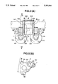
- FIG. 6 is a section taken through the line VI--VI of FIG. 5(A);
- FIG. 7 is a section taken through the line VII--VII of FIG. 6;
- FIG. 8 is a fragmentary enlarged view of FIG. 7.
- FIGS. 1 to 4 show the first embodiment
- FIGS. 5(A) to 8 show the second embodiment.
- Like reference numerals and characters are used through the Figures to designate like or similar parts.
- the invention is embodied with an engine having per cylinder two valves with the same function, e.g., two intake valves or two exhaust valves.
- a rocker arm 1 includes a base portion 102 supported by a main rocker shaft 3 shown in phantom line and driven by two axially spaced low speed cams 21 of a cam shaft 20 for rotatable motion about the axis of the main rocker shaft 3.
- the main rocker shaft 3 and the cam shaft 20 are arranged in parallel and mounted to a cylinder head of the engine.
- the rocker arm 1 has a sub-rocker shaft 16 and a pin 6.
- the sub-rocker shaft 16 and the pin 6 extend in parallel with respect to the main rocker shaft 3 and disposed around the main rocker shaft 3.
- the main rocker shaft 3 is hollowed to define a hydraulic fluid passage 42.
- the base portion 102 of the rocker arm 1 is formed with a bore 104 through which the main rocker shaft 3 extends.
- the rocker arm 1 has a pair of radially extending, with respect to the main rocker shaft 3, portions 106 for operative engagement with the valves 100, respectively.
- the pair of radially extending portions 106 have axially spaced and opposed wall structures 108 defining therebetwen a space 1A (see FIGS. 1 and 2).
- a free cam follower 2 Disposed in the space 1A is a free cam follower 2 which is supported by the sub-rocker shaft 16.
- the free cam follower 2 is driven by a high speed cam 22 of the cam shaft 20 for rotatable motion about the sub-rocker shaft 16.
- the sub-rocker shaft 16 has opposite end portions fixedly received in bores 19 with which the pair of radially extending portions 106 (see FIGS. 1 and 4) are formed.
- the base portion 102 of the rocker arm 1 is formed with a window opening 110 allowing the main rocker shaft 3 to extend into the space 1A.
- the free cam follower 2 includes a prop 29 supporting the free cam follower 2 on that portion of the main rocker shaft 3 which extends into the space 1A.
- the prop 29 is retractable to provide a lost motion connection between the free cam follower 2 and the rocker shaft 3.
- the prop 29 is slidably received in a bore 27 of the free cam follower 2 and arranged for slidable contact with the main rocker shaft 3.
- the prop 29 also includes a lost motion spring 26 disposed in the bore 27 and acting between the prop 29 and the blind end of the bore 27 for biasing the prop 29 against the main rocker shaft 3.
- a mechanism 112 which is shiftable to attain unitary motion of the free cam follower 2 with the rocker arm 1 or to allow relative motion of the free cam follower 2 with respect to the rocker arm 1.
- the mechanism 112 includes a lever 7 rotatably supported by the pin 6.
- the pin 6 has opposite end portions fixedly received in bores 114 (see FIG. 4) with which the pair of radially extending portions 106 are formed.
- the mechanism 112 includes a return spring 9 biasing the lever 7 toward a spring set position as illustrated by the fully drawn line in FIG. 3.
- the return spring 9 is disposed in a bore 8 with which one of the radially extending portions 106 of the rocker arm 1 is formed as shown in FIGS.
- the mechanism 112 also includes a hydraulic piston 31 acting on a lower end portion, viewing in FIG. 3, of the lever 7.
- the hydraulic piston 31 is slidably received in a bore 32 with which the base portion 102 of the rocker arm 1 is formed.
- the base portion 102 is formed also with a hydraulic fluid passage 41 having one end connected to the bore 32 and an opposite end connected to the bore 104.
- the rocker shaft 3 is formed with a radial port 43 establishing fluid communication between the hydraulic passage 41 and the hydraulic fluid passage 42 within the rocker shaft 3.
- the hydraulic piston 31 defines within the bore 32 a hydraulic fluid chamber 34.
- a hydraulic fluid under pressure discharged by a pump Supplied to the hydraulic fluid passage 42 is a hydraulic fluid under pressure discharged by a pump.
- Supply of hydraulic fluid to and discharge thereof from the hydraulic fluid passage 42 is controlled by a two-position shift valve, not shown, operated by a solenoid that is energized in response to an output signal of a control unit.
- the shift valve has a first position wherein the hydraulic fluid is discharged from the hydaulic fluid passage 42 and the hydraulic fluid chamber 34 and a second position wherein the hydraulic fluid is supplied to the hydraulic fluid passage 42 and the hydraulic fluid chamber 34.
- the hydraulic fluid pressure within the hydraulic fluid chamber 34 increases from a low level to a high level owing to this shift.
- control unit Supplied to the control unit are an engine speed signal, an engine coolant temperature signal, a lubricant temperature signal, a signal indicative of charging operation by a turbo charger, a throttle valve position signal, and etc.
- the control strategy followed by the control unit is such that the hydraulic fluid is supplied to the hydraulic fluid chamber 34 during high speed engine operation.
- the hydraulic piston 31 assumes a retracted position as illustrated in the fully drawn line owing to the action of the lever 7 biased by the return spring 9 when the hydraulic fluid is discharged from the hydraulic pressure chamber 34.
- the hydraulic fluid pressure Withih the hydraulic pressure chamber 34 increases from the low level to the high level.
- This increase in hydraulic fluid pressure causes movement of the hydraulic piston 31 from the retracted position toward a projected position as illustrated by the phantom line in FIG. 3.
- This movement of the hydraulic piston 31 causes a counterclockwise rotation of the lever 7 from the fully drawn spring set position toward a locking position as illustrated by the phantom line in FIG. 3.
- the hydraulic piston 31 acts on the lever 7 for urging the lever 7 toward the locking position against the return spring 9.
- the cam follower 2 is recessed toward the prop 29 for catching an upper end 116, viewing in FIG. 3, of the lever 7 to allow the lever 7 to keep the locking position.
- the free cam follower 2 is recessed to define a ceiling wall 118.
- the ceiling wall 118 is arranged and extends in such a manner as to abut the upper end 116 of the lever 7 to provide a positive motion connection between the free cam follower 2 and the lever 7 for unitary motion of the free cam follower 2 with the rocker arm 1 when the lever 7 assumes the locking position.
- the free cam follower 2 has a guide slope 120 (see FIG. 3).
- the angle of this slope 120 is determined such that the slope 120 slides on the upper end portion of the lever 7 without applying any substantial stress to the lever 7 during relative rotational motion of the free cam follower 2 owing to the high speed cam 22.
- the two axially spaced low speed cams 21 and the high speed cam 22 disposed between the two low speed cams 21 are formed integrally with the cam shaft 20.
- the low speed cams 21 have a cam profile designed to meet demands during engine, operation at low speeds
- the high speed cam 22 has a cam profile designed to meet demands during engine operation at high speeds.
- the cam profiles are determined taking into account the requirements for a valve opening period and a valve lift. Specifically, the valve opening period and/or valve lift provided by the cam profile of the high speed cam 22 are greater than that of the low speed cams 21.
- the high speed cam 22 provides a valve lift and a valve opening period which are greater than their counterparts provided by the low speed cams 21.
- the radially extending portions 106 of the rocker arm 1 rotatably support rollers 11 in rolling contact with the low speed cams 21, respectively, while the free cam follower 2 has a follower surface 2A in slidable contact with the high speed cam 22.
- each of the radially extending portions 106 is formed with a rectangular opening, viewing in FIG. 1, receiving the roller 11 and has two spaced side walls 122, 124 and two axially, with respect to the axial of the main rocker shaft 3, spaced end walls 126, 128.
- the two axially spaced end walls 126, 128 are interconnected and axially spaced by the two spaced side walls 122, 124 to define the rectangular opening.
- rollers 11 are rotatbly supported via a needle bearing 14 by a bearing shaft 12 having their ends fixedly inserted into a through hole 13 drilled through the corresponding axially spaced end walls 126, 128 (see FIG. 2).
- the base portion 102 of the rocker arm 1 extends between and defined by the remotest peripheral walls 130, 132 of the radially extending portions 106.
- the lever 7 takes the spring set position as illustrated in FIG. 3. In this position, the motion of the rocker arm 1 follows the cam profile of the low speed cams 21, since the motion of the free cam follower 2 due to the cam profile of the high speed cam 22 is absorbed by compression of the lost motion spring 26 of the retractable prop 29. Thus, rotatable motion of the free cam follower 2 relative to the rocker arm is allowed, without any disturbance of the motion of the rocker arm 1.
- the lever 7 takes the locking position as illustrated by the phantom line in FIG. 3, since the hydraulic piston 31 is projected owing to the pressure build-up in the hydraulic pressure chamber 34 to urge the lever 7 toward the locking position. In this position, unitary motion of the free cam follower 2 with the rocker arm 1 is attained. Since the cam profile of the high speed cam 22 provides a higher valve lift and a longer valve opening period as compared to the low speed cams 21, the roller 11 disengages from the low speed cams 21 during rotatable motion of the free cam follower 2 owing to the high speed cam 22. The motion of the free cam follower 2 is transmitted to the lever 7, the pin 6 and the radially extending portions 106 of the rocker arm 1. The state of the lost motion spring 26 remains unchanged during this motion of the free cam follower 2.
- FIGS. 5(A), 5(B), 6 to 8 the second embodiment is explained.
- This embodiment is substantially the same as the first embodiment.
- the apparatus shown in these Figures is improved over the first embodiment in the use of a low weight rocker arm, and the design of a prop which minimizes sliding friction between a high speed cam and a free cam follower during its motion relative to the rocker arm.
- a rocker arm 1 of the light weight type includes a base portion 102 and a pair of radially extending portions 106.
- Each of the radially extending portions is formed with an opening receiving a roller 11 and has a side wall 122 and two axially, with respect to the axis of a main rocker shaft 3, spaced end walls 126, 128.
- the two axially spaced end walls 126, 128 are interconnected and axially spaced by the side wall 122 to define the opening.
- the radially extending portions 106 have peripheral walls 140, 142.
- the peripheral wall 140 of one of the radially extending portions 106 connects continuously with and shares a common flat surface with the end wall 128 thereof.
- the peripheral wall 142 of the other radially extending portion 102 connects continuously with and shares a common flat surface with the end wall 128 thereof.
- the base portion 102 extends between and defined by the peripheral walls 140, 142 of the radially extending portions 106.
- the side wall 122, the axially spaced end walls 126, 128 and the peripheral wall 142 are formed by a simple cutting process by a cutter in a manner as illustrated by a part of circle and an arrow.
- the side wall 122, the axially spaced end walls 126, 128 and the peripheral wall 10 are formed by the simple cutting process. This makes much contribution to manufacturing cost reduction.
- the width between the peripheral wall 140 and the adjacent one of walls 108 and the width between the other peripheral wall 142 and the adjacent wall 108 are considerably reduced as compared to the first embodiment.
- drilling operation to form bores 18 takes less time and becomes easier, contributing to manufacturing cost reduction.
- a prop 29 is formed with an air bleed hole 29A, and a stop ring 28 is received in a circumferential groove of a cylindrical portion of the prop 29.
- a stop ring 28 is received in a circumferential groove of a cylindrical portion of the prop 29.
- the maximum projection of the prop 29 is defined.
- a follower surface 2A of the free cam follower 2 out of sliding contact with the base circle portion of the cam profile of the high speed cam 22 by appropriately setting the maximum projection of the prop 29. This makes much contribution to a reduction in loss owing to the sliding contact.
- An air bleed hole may be formed through a spring retainer 10 of a return spring 9 for the same purpose.
- the free cam follower 2 is formed with a projection 2D which abuts an edge 1B of the rocker arm 1, thus keeping the free cam follower 2 in an appropriate position during transportation since a cam shaft 20 is removed.
- the lever 7 has the locking position wherein the lever 7 and the free cam follower 2 are joined for attaining unitary motion of the free cam follower with the rocker arm 1 and the spring set position wherein the lever 7 and the free cam follower 2 are separated for allowing relative motion of the free cam follower 2 with respect to the rocker arm 1.
- lever 7 Since the lever 7 is used, parts may be formed with less degree of precision. Adjustment of the height of the follower surface 2A of the free cam follower 2 with the height of the rollers 11 is made by replacing the lever 7 with one having different dimension. These make a reduction in assembly and cost during manufacturing.
- the rocker arm 1 Since it has the two radially extending portions 106 driven by the two low speed cams 21 for actuating the two valves 100, the rocker arm 1 has a great rigidity during engine operation with low speeds. Under a condition where the engine shifts into high speed operation immediately after engine starting and the pressure build-up in the hydraulic pressure, chamber 34 is slow owing to high viscosity of hydraulic fluid, the lever 7 does not reach the locking position. Thus, the rocker arm 1 is kept being driven by the low speed cams 21 at high engine speeds. However, the rocker arm 1 has sufficiently great rigidity to allow such high engine speed operation with low speed cams 21.
Applications Claiming Priority (4)
| Application Number | Priority Date | Filing Date | Title |
|---|---|---|---|
| JP27561791 | 1991-10-23 | ||
| JP3-275617 | 1991-10-23 | ||
| JP4-3100 | 1992-01-10 | ||
| JP00310092A JP3200131B2 (ja) | 1991-10-23 | 1992-01-10 | エンジンの弁作動装置 |
Publications (1)
| Publication Number | Publication Date |
|---|---|
| US5297516A true US5297516A (en) | 1994-03-29 |
Family
ID=26336610
Family Applications (1)
| Application Number | Title | Priority Date | Filing Date |
|---|---|---|---|
| US07/965,071 Expired - Lifetime US5297516A (en) | 1991-10-23 | 1992-10-22 | Valve actuating apparatus |
Country Status (4)
| Country | Link |
|---|---|
| US (1) | US5297516A (ja) |
| JP (1) | JP3200131B2 (ja) |
| DE (1) | DE4235934C2 (ja) |
| GB (1) | GB2260784B (ja) |
Cited By (19)
| Publication number | Priority date | Publication date | Assignee | Title |
|---|---|---|---|---|
| US5415137A (en) * | 1993-05-27 | 1995-05-16 | Audi Ag | Valve actuating mechanism for an internal combustion engine |
| US5431133A (en) * | 1994-05-31 | 1995-07-11 | General Motors Corporation | Low mass two-step valve lifter |
| US5435276A (en) * | 1992-10-09 | 1995-07-25 | Nissan Motor Co., Ltd. | Engine cam change-over mechanism |
| US5452694A (en) * | 1992-12-22 | 1995-09-26 | Unisia Jecs Corporation | Hydraulic variable lift engine valve gear |
| US5529033A (en) * | 1995-05-26 | 1996-06-25 | Eaton Corporation | Multiple rocker arm valve control system |
| US5531203A (en) * | 1994-01-25 | 1996-07-02 | Honda Giken Kogyo Kabushiki Kaisha | Catalyst activating system in multi-cylinder internal combustion engine |
| US5570664A (en) * | 1994-09-02 | 1996-11-05 | Nissan Motor Co., Ltd. | Engine valve drive device |
| US5615647A (en) * | 1995-03-28 | 1997-04-01 | Eaton Corporation | Latch assembly for a valve control system |
| DE19642059A1 (de) * | 1995-10-12 | 1997-04-17 | Unisia Jecs Corp | Ventilbetätigungsvorrichtung für einen Motor |
| US5622145A (en) * | 1994-12-21 | 1997-04-22 | Unisia Jecs Corporation | Cylinder valve operating apparatus |
| US5660153A (en) * | 1995-03-28 | 1997-08-26 | Eaton Corporation | Valve control system |
| US5701857A (en) * | 1995-10-12 | 1997-12-30 | Unisia Jecs Corporation | Cylinder valve operating system |
| US5794576A (en) * | 1996-02-20 | 1998-08-18 | Unisia Jecs Corporation | Engine cylinder valve controlling apparatus |
| EP0893181A1 (en) * | 1997-07-01 | 1999-01-27 | Unisia Jecs Corporation | Method and mould for investment casting of engine rocker arms |
| US5975036A (en) * | 1997-07-01 | 1999-11-02 | Unisia Jecs Corporation | Variable valve actuation apparatus |
| US20040003789A1 (en) * | 2002-07-04 | 2004-01-08 | Peter Kreuter | Methods and apparatus for providing variable valve lift for camshaft-actuated valves |
| US20040063041A1 (en) * | 2000-04-26 | 2004-04-01 | Ritdisplay Corporation | Method for fabricating an anti-glare pixel-defining layer on an OLED panel |
| US7963260B2 (en) | 2005-08-08 | 2011-06-21 | Meta Motoren- Und Energie-Technik Gmbh | Switchable valve actuating mechanism |
| EP4194667A1 (en) * | 2021-12-07 | 2023-06-14 | AVL Hungary Kft. | Internal combustion engines with variable valve actuation |
Families Citing this family (3)
| Publication number | Priority date | Publication date | Assignee | Title |
|---|---|---|---|---|
| US5227689A (en) * | 1989-08-11 | 1993-07-13 | Mabuchi Motor Co., Ltd. | Metal-filled graphite for miniature motors and method of making same |
| DE19749079B4 (de) * | 1997-11-06 | 2007-12-20 | Schaeffler Kg | Nockenfolger eines Ventiltriebs einer Brennkraftmaschine |
| JP4476241B2 (ja) | 2005-06-20 | 2010-06-09 | 日立オートモティブシステムズ株式会社 | 内燃機関の動弁装置 |
Citations (12)
| Publication number | Priority date | Publication date | Assignee | Title |
|---|---|---|---|---|
| DE2753197A1 (de) * | 1976-12-15 | 1978-06-22 | Eaton Corp | Ventilsteuervorrichtung |
| US4203397A (en) * | 1978-06-14 | 1980-05-20 | Eaton Corporation | Engine valve control mechanism |
| JPS6357806A (ja) * | 1986-08-27 | 1988-03-12 | Honda Motor Co Ltd | 内燃機関の動弁装置 |
| JPS63167016A (ja) * | 1986-12-27 | 1988-07-11 | Honda Motor Co Ltd | 多気筒内燃機関の動弁装置 |
| US4762096A (en) * | 1987-09-16 | 1988-08-09 | Eaton Corporation | Engine valve control mechanism |
| US4768475A (en) * | 1986-02-28 | 1988-09-06 | Fuji Jukogyo Kabushiki Kaisha | Valve mechanism for an automotive engine |
| US4768467A (en) * | 1986-01-23 | 1988-09-06 | Fuji Jukogyo Kabushiki Kaisha | Valve operating system for an automotive engine |
| US4844023A (en) * | 1987-01-08 | 1989-07-04 | Honda Giken Kogyo Kabushiki Kaisha | Valve operating device for internal combustion engine |
| EP0420159A1 (en) * | 1989-09-25 | 1991-04-03 | Nissan Motor Co., Ltd. | Variable valve timing rocker arm arrangement for internal combustion engine |
| US5020488A (en) * | 1989-11-22 | 1991-06-04 | Fuji Jukogyo Kabushiki Kaisha | Valve mechanism for an internal combustion engine |
| WO1991012415A1 (en) * | 1990-02-16 | 1991-08-22 | Group Lotus Plc | Cam mechanisms |
| US5046462A (en) * | 1989-10-12 | 1991-09-10 | Nissan Motor Co., Ltd. | Rocker arm arrangement for variable valve timing type internal combustion engine valve train |
Family Cites Families (2)
| Publication number | Priority date | Publication date | Assignee | Title |
|---|---|---|---|---|
| US4799870A (en) * | 1987-01-23 | 1989-01-24 | Mcmaster Harold | Fluid power transfer device |
| IT1240107B (it) * | 1990-02-16 | 1993-11-27 | Ferrari Spa | Sistema di distribuzione variabile, in particolare per un motore endotermico. |
-
1992
- 1992-01-10 JP JP00310092A patent/JP3200131B2/ja not_active Expired - Fee Related
- 1992-10-22 US US07/965,071 patent/US5297516A/en not_active Expired - Lifetime
- 1992-10-23 DE DE4235934A patent/DE4235934C2/de not_active Expired - Fee Related
- 1992-10-23 GB GB9222318A patent/GB2260784B/en not_active Expired - Fee Related
Patent Citations (14)
| Publication number | Priority date | Publication date | Assignee | Title |
|---|---|---|---|---|
| US4151817A (en) * | 1976-12-15 | 1979-05-01 | Eaton Corporation | Engine valve control mechanism |
| DE2753197A1 (de) * | 1976-12-15 | 1978-06-22 | Eaton Corp | Ventilsteuervorrichtung |
| US4203397A (en) * | 1978-06-14 | 1980-05-20 | Eaton Corporation | Engine valve control mechanism |
| US4768467A (en) * | 1986-01-23 | 1988-09-06 | Fuji Jukogyo Kabushiki Kaisha | Valve operating system for an automotive engine |
| US4768475A (en) * | 1986-02-28 | 1988-09-06 | Fuji Jukogyo Kabushiki Kaisha | Valve mechanism for an automotive engine |
| JPS6357806A (ja) * | 1986-08-27 | 1988-03-12 | Honda Motor Co Ltd | 内燃機関の動弁装置 |
| JPS63167016A (ja) * | 1986-12-27 | 1988-07-11 | Honda Motor Co Ltd | 多気筒内燃機関の動弁装置 |
| US4844023A (en) * | 1987-01-08 | 1989-07-04 | Honda Giken Kogyo Kabushiki Kaisha | Valve operating device for internal combustion engine |
| US4762096A (en) * | 1987-09-16 | 1988-08-09 | Eaton Corporation | Engine valve control mechanism |
| EP0420159A1 (en) * | 1989-09-25 | 1991-04-03 | Nissan Motor Co., Ltd. | Variable valve timing rocker arm arrangement for internal combustion engine |
| US5085182A (en) * | 1989-09-25 | 1992-02-04 | Nissan Motor Co., Ltd. | Variable valve timing rocker arm arrangement for internal combustion engine |
| US5046462A (en) * | 1989-10-12 | 1991-09-10 | Nissan Motor Co., Ltd. | Rocker arm arrangement for variable valve timing type internal combustion engine valve train |
| US5020488A (en) * | 1989-11-22 | 1991-06-04 | Fuji Jukogyo Kabushiki Kaisha | Valve mechanism for an internal combustion engine |
| WO1991012415A1 (en) * | 1990-02-16 | 1991-08-22 | Group Lotus Plc | Cam mechanisms |
Cited By (22)
| Publication number | Priority date | Publication date | Assignee | Title |
|---|---|---|---|---|
| US5435276A (en) * | 1992-10-09 | 1995-07-25 | Nissan Motor Co., Ltd. | Engine cam change-over mechanism |
| US5452694A (en) * | 1992-12-22 | 1995-09-26 | Unisia Jecs Corporation | Hydraulic variable lift engine valve gear |
| US5415137A (en) * | 1993-05-27 | 1995-05-16 | Audi Ag | Valve actuating mechanism for an internal combustion engine |
| US5531203A (en) * | 1994-01-25 | 1996-07-02 | Honda Giken Kogyo Kabushiki Kaisha | Catalyst activating system in multi-cylinder internal combustion engine |
| US5431133A (en) * | 1994-05-31 | 1995-07-11 | General Motors Corporation | Low mass two-step valve lifter |
| US5570664A (en) * | 1994-09-02 | 1996-11-05 | Nissan Motor Co., Ltd. | Engine valve drive device |
| US5622145A (en) * | 1994-12-21 | 1997-04-22 | Unisia Jecs Corporation | Cylinder valve operating apparatus |
| US5660153A (en) * | 1995-03-28 | 1997-08-26 | Eaton Corporation | Valve control system |
| US5615647A (en) * | 1995-03-28 | 1997-04-01 | Eaton Corporation | Latch assembly for a valve control system |
| US5529033A (en) * | 1995-05-26 | 1996-06-25 | Eaton Corporation | Multiple rocker arm valve control system |
| DE19642059C2 (de) * | 1995-10-12 | 2001-03-29 | Unisia Jecs Corp | Ventilbetätigungsvorrichtung für einen Motor |
| US5682847A (en) * | 1995-10-12 | 1997-11-04 | Unisia Jecs Corporation | Valve actuating device for engine |
| US5701857A (en) * | 1995-10-12 | 1997-12-30 | Unisia Jecs Corporation | Cylinder valve operating system |
| DE19642059A1 (de) * | 1995-10-12 | 1997-04-17 | Unisia Jecs Corp | Ventilbetätigungsvorrichtung für einen Motor |
| US5794576A (en) * | 1996-02-20 | 1998-08-18 | Unisia Jecs Corporation | Engine cylinder valve controlling apparatus |
| EP0893181A1 (en) * | 1997-07-01 | 1999-01-27 | Unisia Jecs Corporation | Method and mould for investment casting of engine rocker arms |
| US5975036A (en) * | 1997-07-01 | 1999-11-02 | Unisia Jecs Corporation | Variable valve actuation apparatus |
| US20040063041A1 (en) * | 2000-04-26 | 2004-04-01 | Ritdisplay Corporation | Method for fabricating an anti-glare pixel-defining layer on an OLED panel |
| US20040003789A1 (en) * | 2002-07-04 | 2004-01-08 | Peter Kreuter | Methods and apparatus for providing variable valve lift for camshaft-actuated valves |
| US6848402B2 (en) * | 2002-07-04 | 2005-02-01 | Meta Motoren-Und Energie-Technik Gmbh | Methods and apparatus for providing variable valve lift for camshaft-actuated valves |
| US7963260B2 (en) | 2005-08-08 | 2011-06-21 | Meta Motoren- Und Energie-Technik Gmbh | Switchable valve actuating mechanism |
| EP4194667A1 (en) * | 2021-12-07 | 2023-06-14 | AVL Hungary Kft. | Internal combustion engines with variable valve actuation |
Also Published As
| Publication number | Publication date |
|---|---|
| DE4235934A1 (de) | 1993-04-29 |
| JP3200131B2 (ja) | 2001-08-20 |
| DE4235934C2 (de) | 2003-04-10 |
| JPH05171909A (ja) | 1993-07-09 |
| GB9222318D0 (en) | 1992-12-09 |
| GB2260784B (en) | 1994-09-07 |
| GB2260784A (en) | 1993-04-28 |
Similar Documents
| Publication | Publication Date | Title |
|---|---|---|
| US5297516A (en) | Valve actuating apparatus | |
| US5351662A (en) | Valve control means | |
| USRE33310E (en) | Valve operating and interrupting mechanism for internal combustion engine | |
| EP0515520B1 (en) | Valve control means | |
| US4576128A (en) | Valve operation stopping means for multi-cylinder engine | |
| US5960750A (en) | Device for changing compression of a reciprocating piston internal combustion engine | |
| JP2778930B2 (ja) | 二段弁リフタ | |
| EP0420159B1 (en) | Variable valve timing rocker arm arrangement for internal combustion engine | |
| US5386806A (en) | Cam mechanisms | |
| US7565887B2 (en) | Valve actuation device of internal combustion engine | |
| JPH06299821A (ja) | 2段弁リフタおよび弁リフト機構 | |
| JPH068604B2 (ja) | 内燃機関の弁作動状態切換装置 | |
| US5359970A (en) | Valve drive for an internal combustion engine | |
| US4463714A (en) | Hydraulic lifter | |
| US5239952A (en) | Valve actuating apparatus | |
| US5694894A (en) | Valve control means | |
| EP0695395B1 (en) | Valve control means | |
| EP0199569B1 (en) | Oil supply system in an internal combustion engine | |
| US7353785B2 (en) | Compression ratio variable device of internal combustion engine | |
| US5622145A (en) | Cylinder valve operating apparatus | |
| US4481919A (en) | Intake/exhaust valve assembly for an internal combustion engine | |
| US5701857A (en) | Cylinder valve operating system | |
| US5183015A (en) | Valve operating apparatus | |
| US5570664A (en) | Engine valve drive device | |
| JP3074202B2 (ja) | 内燃機関の動弁装置 |
Legal Events
| Date | Code | Title | Description |
|---|---|---|---|
| AS | Assignment |
Owner name: ATSUGI UNISIA CORPORATION, JAPAN Free format text: ASSIGNMENT OF ASSIGNORS INTEREST.;ASSIGNOR:HARA, SEINOSUKE;REEL/FRAME:006383/0941 Effective date: 19921119 |
|
| STCF | Information on status: patent grant |
Free format text: PATENTED CASE |
|
| FPAY | Fee payment |
Year of fee payment: 4 |
|
| FPAY | Fee payment |
Year of fee payment: 8 |
|
| FEPP | Fee payment procedure |
Free format text: PAYOR NUMBER ASSIGNED (ORIGINAL EVENT CODE: ASPN); ENTITY STATUS OF PATENT OWNER: LARGE ENTITY |
|
| AS | Assignment |
Owner name: HITACHI, LTD., JAPAN Free format text: MERGER;ASSIGNOR:HITACHI UNISIA AUTOMOTIVE, LTD.;REEL/FRAME:016256/0342 Effective date: 20040927 |
|
| FPAY | Fee payment |
Year of fee payment: 12 |