US5259352A - Membrane fuel pump for a membrane carburetor - Google Patents
Membrane fuel pump for a membrane carburetor Download PDFInfo
- Publication number
- US5259352A US5259352A US08/013,970 US1397093A US5259352A US 5259352 A US5259352 A US 5259352A US 1397093 A US1397093 A US 1397093A US 5259352 A US5259352 A US 5259352A
- Authority
- US
- United States
- Prior art keywords
- membrane
- pressure
- chamber
- pump
- fuel pump
- Prior art date
- Legal status (The legal status is an assumption and is not a legal conclusion. Google has not performed a legal analysis and makes no representation as to the accuracy of the status listed.)
- Expired - Fee Related
Links
Images

Classifications
-
- F—MECHANICAL ENGINEERING; LIGHTING; HEATING; WEAPONS; BLASTING
- F04—POSITIVE - DISPLACEMENT MACHINES FOR LIQUIDS; PUMPS FOR LIQUIDS OR ELASTIC FLUIDS
- F04B—POSITIVE-DISPLACEMENT MACHINES FOR LIQUIDS; PUMPS
- F04B43/00—Machines, pumps, or pumping installations having flexible working members
- F04B43/02—Machines, pumps, or pumping installations having flexible working members having plate-like flexible members, e.g. diaphragms
- F04B43/06—Pumps having fluid drive
- F04B43/067—Pumps having fluid drive the fluid being actuated directly by a piston
-
- F—MECHANICAL ENGINEERING; LIGHTING; HEATING; WEAPONS; BLASTING
- F02—COMBUSTION ENGINES; HOT-GAS OR COMBUSTION-PRODUCT ENGINE PLANTS
- F02M—SUPPLYING COMBUSTION ENGINES IN GENERAL WITH COMBUSTIBLE MIXTURES OR CONSTITUENTS THEREOF
- F02M17/00—Carburettors having pertinent characteristics not provided for in, or of interest apart from, the apparatus of preceding main groups F02M1/00 - F02M15/00
- F02M17/02—Floatless carburettors
- F02M17/04—Floatless carburettors having fuel inlet valve controlled by diaphragm
-
- F—MECHANICAL ENGINEERING; LIGHTING; HEATING; WEAPONS; BLASTING
- F02—COMBUSTION ENGINES; HOT-GAS OR COMBUSTION-PRODUCT ENGINE PLANTS
- F02M—SUPPLYING COMBUSTION ENGINES IN GENERAL WITH COMBUSTIBLE MIXTURES OR CONSTITUENTS THEREOF
- F02M37/00—Apparatus or systems for feeding liquid fuel from storage containers to carburettors or fuel-injection apparatus; Arrangements for purifying liquid fuel specially adapted for, or arranged on, internal-combustion engines
- F02M37/02—Feeding by means of suction apparatus, e.g. by air flow through carburettors
-
- F—MECHANICAL ENGINEERING; LIGHTING; HEATING; WEAPONS; BLASTING
- F02—COMBUSTION ENGINES; HOT-GAS OR COMBUSTION-PRODUCT ENGINE PLANTS
- F02M—SUPPLYING COMBUSTION ENGINES IN GENERAL WITH COMBUSTIBLE MIXTURES OR CONSTITUENTS THEREOF
- F02M37/00—Apparatus or systems for feeding liquid fuel from storage containers to carburettors or fuel-injection apparatus; Arrangements for purifying liquid fuel specially adapted for, or arranged on, internal-combustion engines
- F02M37/04—Feeding by means of driven pumps
- F02M37/046—Arrangements for driving diaphragm-type pumps
Definitions
- the invention relates to a membrane fuel pump for a membrane carburetor for an internal combustion engine such as a two-stroke engine of a portable handheld work apparatus such as a motor-driven chain saw or the like.
- a major part of the fuel volume pumped in idle flows back via the bypass during the idle mode of a two-stroke engine because the pressure controller allows only a small quantity of fuel to pass into the control chamber.
- the average pressure measured during idle on the pressure end of the pump is less by a factor of 10 than for a pump without a bypass so that the pressure controller operates without disturbance in accordance with its characteristic and main nozzle drip is substantially avoided.
- a pumping volume of the pump adapted approximately to the engine speed is obtained at an average pressure to be controlled by the pressure controller.
- the reduction of the pumping capacity is disadvantageous which is caused by the bypass so that the pump must, in most cases, be configured larger to compensate for this reduction.
- the invention is directed to a membrane fuel pump for a membrane carburetor of an internal combustion engine including a two-stroke engine of a portable handheld work apparatus such as a motor-driven chain saw and the like.
- the carburetor has a pressure controller and the engine has a crankcase wherein pressure fluctuates during operation of the engine.
- the membrane fuel pump includes: a housing defining an enclosed space; a pump membrane mounted in the housing and partitioning the space into a pump chamber and a drive chamber; a line connecting the crankcase to the drive chamber for charging the drive chamber with the pressure in the crankcase; fuel supply means for supplying fuel to the pump chamber; a first check valve interposed between the pump chamber and the fuel supply means; pressure connection means for connecting the pump chamber to the pressure controller of the membrane carburetor; a second check valve interposed between the pressure connection means and the pump chamber so as to permit fuel to flow from the pump chamber through the pressure connection means to the pressure controller of the carburetor when the second check valve is open and to interrupt the flow of fuel when the second check valve is closed; the housing including a bypass channel connecting the pressure connection means to the fuel supply means; and, valve means interposed between the pressure connection means and the bypass channel and being responsive to the pressure present in the pressure connection means for switching the valve means between a first position wherein the bypass channel is open to the pressure connection means and a second position wherein the bypass channel is
- the bypass can be blocked by a valve having a valve member controlled by the pressure present in the pressure connection. For this reason, a closing of the bypass is ensured when too great a pressure drop is present in the pressure connection thereby reliably avoiding making the mixture lean. On the other hand, it is also ensured that a pressure, which is too high, will be reduced through the bypass especially during idle since a pressure, which is too high, leads to a displacement of the valve member in the sense of an opening of the blocking valve.
- the valve member is advantageously configured as a membrane which delimits a control chamber through which a flow passes from the pressure connection to the pressure controller.
- This valve member also covers the bypass in its at-rest position.
- the bypass starts at and extends from the control chamber.
- the membrane is continuously subjected to the pressure present at the pressure connection because the membrane delimits the control chamber. For this reason, the membrane can react to pressure differences by corresponding deflections.
- the bypass is covered by the edge region of the membrane and is therefore always opened when the membrane is so far deflected because of a high pressure that the edge region lifts off the covered bypass and opens the latter. If in contrast, the pressure drop is extreme, then the membrane returns to its at-rest position and closes the bypass so that the complete pump capacity is available.
- a spring is mounted on the side of this membrane facing away from the control chamber to ensure a reliable closure.
- the spring is preferably a helical spring and applies a force to the membrane in the direction toward its at-rest position.
- the membrane is charged on its side facing away from the control chamber with intake-pipe pressure branched off downstream of the throttle flap in order to ensure a clean opening of the check valve during idle.
- the underpressure always operates in the sense of a displacement of the membrane in the direction of pressure chamber when the throttle flap is closed and the underpressure downstream of the throttle flap takes on significant values. In this way, the edge region of the membrane lifts away from the bypass and the pump is short circuited.
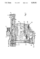
- FIG. 1 is a schematic of a membrane fuel pump according to the invention having a blocking valve and shown with a membrane carburetor connected thereto;
- FIG. 2 is a schematic of a membrane fuel pump of the kind shown in FIG. 1 equipped with a blocking valve charged with pressure from the intake pipe.
- the membrane carburetor 29 shown in the drawings is provided especially for a two-stroke internal combustion engine mounted in portable handheld work apparatus such as chain saws, cutoff machines, brushcutters or the like.
- the carburetor is supplied via a pressure controller 15 from a membrane fuel pump 5 which draws fuel by suction from a fuel tank (not shown) and pumps the fuel to the pressure controller 15.
- the fuel first flows via the feed line 2 of the fuel tank into a compensating chamber 3 and from there via a check valve 4 into a pump chamber 7 of the fuel pump 5.
- the check valve 4 is configured as a flap valve.
- the pump chamber 7 is partitioned from a drive chamber 8 of the fuel pump 5 by a membrane 6.
- the drive chamber 8 communicates with the crankcase 9 of an internal combustion engine 1 such as a two-stroke engine and is charged by the changing crankcase internal pressure in this manner.
- the membrane 6 deflects in the sense of reducing the volume of the pump chamber 7 and the fuel in the pump chamber 7 is subjected to pressure.
- the check valve 4 closes and a check valve 10 opens.
- the check valve 10 is arranged on the pressure end of the pump 5 and is likewise configured as a flap valve.
- the fuel flows via a pressure connection 50 into a control chamber 60 and flows from there to the pressure controller 15 via a fine filter 12 and a pressure line 11.
- the pressure controller 15 of the membrane carburetor 29 comprises essentially a control chamber 18 which is partitioned by a control membrane 16 from a chamber 17 at atmospheric pressure.
- One end of a controller lever 14 is applied to the center of the control membrane 16 and the other end of this lever controls a feed valve 13.
- the feed valve 13 is configured as a needle valve. It can also be advantageous to configure the feed valve as a flat valve.
- the controller lever 14 is biased by a spring 14a in the direction of closure of the feed valve 13 so that the inlet to the control chamber 18 is at first closed.
- a main nozzle channel 20 leads from the control chamber 18 via a main nozzle 22 into the intake pipe 25 of the internal combustion engine 1.
- the flow cross section of the main nozzle channel 20 is adjustable by means of a control screw 21.
- the main nozzle 22 is closed by a check valve 23 which opens into the intake pipe 25.
- the main nozzle 22 opens into the intake pipe 25 in a region between a starter flap 24 and a throttle flap 26.
- an idle nozzle channel 32 leads to an idle nozzle 27 which opens into the intake pipe 25 downstream of the throttle flap 26 when the throttle flap is in the idle position (shown in phantom outline in FIG. 1).
- the opening cross section of the idle nozzle channel 32 is adjustable by a control screw 30.
- a bypass channel 28 branches off from the idle nozzle channel 32 downstream of the control screw 30. The bypass channel 28 opens into the intake pipe 25 forward of the throttle flap 26 (in its idle position shown in phantom outline in FIG. 1) when viewed in the flow direction of the intake air.
- the intake pipe 25 is shown fully open in the full-load position shown in FIG. 1 so that the fuel is drawn in by suction via the main nozzle channel 20 (arrow 19) as well as via the idle nozzle channel 32 (arrow 19a) into the venturi section of the intake pipe 25.
- the underpressure in the control chamber 18 developed thereby leads to a displacement of the control membrane 16 whereby the controller lever 14 is actuated so that the feed valve 13 is opened and the fuel pumped by the membrane fuel pump 5 flows in.
- the pressure connection 50 of the fuel pump 5 is connected to its intake connection 40 via a bypass 70 in order to ensure a reliable closure of the check valve 23 of the main nozzle 22 during the idle position.
- a throttle 71 is mounted in the bypass 70.
- the bypass 70 branches off from a control chamber 60 into which the pressure connection 50 opens and from which the pressure line 11 leads to the pressure controller 15.
- the control chamber 60 is delimited by a membrane 61 and a pressure chamber 62 is formed on the side of the membrane facing away from the control chamber 60.
- the pressure chamber 62 is advantageously vented to the atmosphere via an opening 63.
- the membrane 61 is disposed transversely to the bypass 70 and covers the bypass in its at-rest position shown in FIG. 1.
- the membrane 61 then defines a valve member which, together with the opening of the bypass 70 defines a valve 72 by means of which the bypass can be blocked.
- the opening of the bypass 70 communicates with the control chamber 60 when the valve 72 is open.
- the membrane 61 is biased with a force via a spring 64 on the side of the membrane facing away from the control chamber 60.
- the spring 64 is preferably a helical spring.
- the membrane 61 covers the bypass 70 with its edge region 61a with the spring 64 being disposed opposite the bypass 70.
- a common foil 80 defines the following: membrane 61 delimiting the control chamber 60, the membrane 6 of the fuel pump 5 and the flaps of the check valves 4 and 10.
- the foil 80 is held between two housing parts 81 and 82 of the fuel pump 5.
- the fuel pump is required to develop an increased suction power during operation of the engine, for example, when the vent of the fuel tank is blocked, then the pressure at the pressure end of the pump 5 in the control chamber 60 first drops and the membrane 61 effects a closure of the bypass 70. As soon as the bypass is closed, the complete pumping capacity of the pump 5 is available to pump the required fuel quantity to the pressure controller 15 against the increased suction pressure, this fuel quantity being required for a trouble-free operation of the engine.
- the pressure chamber 62 is closed off against the atmosphere and is connected via a pressure channel 83 to the intake pipe 25.
- the pressure channel 83 taps from the intake channel 25 downstream of the throttle flap shown in the idle position and preferably near the throttle flap. Underpressure develops downstream of the throttle flap in the intake pipe section 25a when the throttle flap is closed (solid outline), that is, during idle.
- the connection of the pressure channel 83 then causes this underpressure to also be present in the pressure chamber 62 and causes the membrane 61 to arcuately deflect into the pressure chamber 62 so that the bypass 70 is opened. In idle, a drop of the quantity pumped by the pump 5 as well as a pressure drop in the pressure line 11 to the pressure controller 15 is achieved.
- the throttle flap 26 pivots in the direction of arrow 26a into the position shown in phantom outline and passes the opening 84 of the pressure channel 83 whereby the pressure chamber 62 is charged with the pressure present in the intake pipe upstream of the throttle flap. This pressure is higher than the underpressure which was previously present.
- the membrane 61 returns toward its at-rest position and the helical spring 64 effects a closure of the bypass 70 and the fuel pump operates at full pumping capacity. In this way, a switching of the valve 72 is effected in correspondence to the position of the throttle flap 26.
- a closure of the bypass 70 can be produced by an actuation of the throttle flap 26 or the throttle lever (with a corresponding selection of the membrane stiffness and/or the helical spring 64 independently of the pressure present in the control chamber 60), that is, a switchover of the pump 5 to full pumping capacity can take place.
Landscapes
- Engineering & Computer Science (AREA)
- Mechanical Engineering (AREA)
- General Engineering & Computer Science (AREA)
- Chemical & Material Sciences (AREA)
- Combustion & Propulsion (AREA)
- Reciprocating Pumps (AREA)
- Control Of The Air-Fuel Ratio Of Carburetors (AREA)
Applications Claiming Priority (2)
| Application Number | Priority Date | Filing Date | Title |
|---|---|---|---|
| DE9201455[U] | 1992-02-06 | ||
| DE9201455U DE9201455U1 (zh) | 1992-02-06 | 1992-02-06 |
Publications (1)
| Publication Number | Publication Date |
|---|---|
| US5259352A true US5259352A (en) | 1993-11-09 |
Family
ID=6875819
Family Applications (1)
| Application Number | Title | Priority Date | Filing Date |
|---|---|---|---|
| US08/013,970 Expired - Fee Related US5259352A (en) | 1992-02-06 | 1993-02-05 | Membrane fuel pump for a membrane carburetor |
Country Status (3)
| Country | Link |
|---|---|
| US (1) | US5259352A (zh) |
| JP (1) | JPH05280439A (zh) |
| DE (1) | DE9201455U1 (zh) |
Cited By (24)
| Publication number | Priority date | Publication date | Assignee | Title |
|---|---|---|---|---|
| US5419686A (en) * | 1992-07-18 | 1995-05-30 | Andreas Stihl | Fuel pump for an internal combustion engine |
| US5429095A (en) * | 1992-12-02 | 1995-07-04 | Tk Carburetor Co., Ltd. | Apparatus for supplying fuel to an engine through a diaphragm-type carburetor |
| US5615643A (en) * | 1996-07-01 | 1997-04-01 | Orbital Engine Company (Australia) Pty. Limited | Fuel pumps for internal combustion engines |
| US5732685A (en) * | 1995-09-22 | 1998-03-31 | Yamaha Hatsudoki Kabushiki Kaisha | Fuel supply system for watercraft |
| US5934885A (en) * | 1994-10-07 | 1999-08-10 | Bayer Corporation | Reagent pump assembly |
| US6017199A (en) * | 1998-05-20 | 2000-01-25 | U.S.A. Zama, Inc. | Diaphragm carburetor for four cycle engines |
| US6032654A (en) * | 1997-06-10 | 2000-03-07 | Sanshin Kogyo Kabushiki Kaisha | Fuel supply for injected marine engine |
| US6158972A (en) * | 1999-03-16 | 2000-12-12 | Federal-Mogul World Wide, Inc. | Two stage pulse pump |
| US6244915B1 (en) | 1996-12-30 | 2001-06-12 | Yamaha Hatsudoki Kabushiki Kaisha | Fuel system and arrangement for small watercraft |
| US20060005954A1 (en) * | 2004-07-12 | 2006-01-12 | Orr Troy J | Heat exchanger apparatus for a recirculation loop and related methods and systems |
| US20070077156A1 (en) * | 2005-07-13 | 2007-04-05 | Orr Troy J | Double diaphragm pump and related methods |
| US20080077068A1 (en) * | 2005-07-13 | 2008-03-27 | Purity Solutions Llc | Diaphragm pump and related methods |
| US20090137940A1 (en) * | 2007-11-26 | 2009-05-28 | Purity Solutions Llc | Diaphragm pump and related systems and methods |
| JP2014025460A (ja) * | 2012-07-30 | 2014-02-06 | Honda Motor Co Ltd | 内燃機関の燃料供給装置 |
| US8926835B2 (en) | 2002-06-04 | 2015-01-06 | Fresenius Medical Care Deustschland Gmbh | Dialysis systems and related methods |
| US8986254B2 (en) | 2009-03-20 | 2015-03-24 | Fresenius Medical Care Holdings, Inc. | Medical fluid pump systems and related components and methods |
| US9011114B2 (en) | 2011-03-09 | 2015-04-21 | Fresenius Medical Care Holdings, Inc. | Medical fluid delivery sets and related systems and methods |
| US9180240B2 (en) | 2011-04-21 | 2015-11-10 | Fresenius Medical Care Holdings, Inc. | Medical fluid pumping systems and related devices and methods |
| WO2016010713A1 (en) * | 2014-07-16 | 2016-01-21 | Flowserve Management Company | Improved diaphragm pump |
| US9421314B2 (en) | 2009-07-15 | 2016-08-23 | Fresenius Medical Care Holdings, Inc. | Medical fluid cassettes and related systems and methods |
| US9500188B2 (en) | 2012-06-11 | 2016-11-22 | Fresenius Medical Care Holdings, Inc. | Medical fluid cassettes and related systems and methods |
| US9561323B2 (en) | 2013-03-14 | 2017-02-07 | Fresenius Medical Care Holdings, Inc. | Medical fluid cassette leak detection methods and devices |
| US9610392B2 (en) | 2012-06-08 | 2017-04-04 | Fresenius Medical Care Holdings, Inc. | Medical fluid cassettes and related systems and methods |
| US10117985B2 (en) | 2013-08-21 | 2018-11-06 | Fresenius Medical Care Holdings, Inc. | Determining a volume of medical fluid pumped into or out of a medical fluid cassette |
Families Citing this family (3)
| Publication number | Priority date | Publication date | Assignee | Title |
|---|---|---|---|---|
| DE9420396U1 (de) * | 1994-12-21 | 1996-04-18 | Dolmar Gmbh | Einrichtung zur Verbesserung des Startverhaltens von Verbrennungsmotoren |
| US6446611B2 (en) | 2000-03-06 | 2002-09-10 | Nippon Carburetor Co., Ltd. (Kabushikikaisha Nihon Kikaki Seisakusho) | Pulsation type diaphragm pump |
| DE102021204407A1 (de) | 2021-05-03 | 2022-11-03 | Robert Bosch Gesellschaft mit beschränkter Haftung | Verfahren zum Betreiben einer Pumpe und Fluid-Versorgungssystem |
Citations (6)
| Publication number | Priority date | Publication date | Assignee | Title |
|---|---|---|---|---|
| US4430048A (en) * | 1980-12-29 | 1984-02-07 | Lewa Herbert Ott Gmbh & Co. | Diaphragm pump with a diaphragm clamped in pressure-balancing arrangement |
| US4473340A (en) * | 1981-10-08 | 1984-09-25 | Outboard Marine Corporation | Combined fluid pressure actuated fuel and oil pump |
| US4813391A (en) * | 1987-08-15 | 1989-03-21 | Andreas Stihl | Arrangement for injecting fuel for a two-stroke engine |
| US4928390A (en) * | 1989-08-22 | 1990-05-29 | Textron, Inc. | Carburetor and oil pump assembly and method of making the same |
| US4932370A (en) * | 1988-09-16 | 1990-06-12 | Andreas Stihl | Fuel injection arrangement |
| US4976246A (en) * | 1987-10-22 | 1990-12-11 | Andreas Stihl | Fuel-injection pump arrangement for a two-stroke engine of a handheld portable tool |
-
1992
- 1992-02-06 DE DE9201455U patent/DE9201455U1/de not_active Expired - Lifetime
-
1993
- 1993-01-20 JP JP5007487A patent/JPH05280439A/ja active Pending
- 1993-02-05 US US08/013,970 patent/US5259352A/en not_active Expired - Fee Related
Patent Citations (6)
| Publication number | Priority date | Publication date | Assignee | Title |
|---|---|---|---|---|
| US4430048A (en) * | 1980-12-29 | 1984-02-07 | Lewa Herbert Ott Gmbh & Co. | Diaphragm pump with a diaphragm clamped in pressure-balancing arrangement |
| US4473340A (en) * | 1981-10-08 | 1984-09-25 | Outboard Marine Corporation | Combined fluid pressure actuated fuel and oil pump |
| US4813391A (en) * | 1987-08-15 | 1989-03-21 | Andreas Stihl | Arrangement for injecting fuel for a two-stroke engine |
| US4976246A (en) * | 1987-10-22 | 1990-12-11 | Andreas Stihl | Fuel-injection pump arrangement for a two-stroke engine of a handheld portable tool |
| US4932370A (en) * | 1988-09-16 | 1990-06-12 | Andreas Stihl | Fuel injection arrangement |
| US4928390A (en) * | 1989-08-22 | 1990-05-29 | Textron, Inc. | Carburetor and oil pump assembly and method of making the same |
Cited By (44)
| Publication number | Priority date | Publication date | Assignee | Title |
|---|---|---|---|---|
| US5419686A (en) * | 1992-07-18 | 1995-05-30 | Andreas Stihl | Fuel pump for an internal combustion engine |
| US5429095A (en) * | 1992-12-02 | 1995-07-04 | Tk Carburetor Co., Ltd. | Apparatus for supplying fuel to an engine through a diaphragm-type carburetor |
| US5934885A (en) * | 1994-10-07 | 1999-08-10 | Bayer Corporation | Reagent pump assembly |
| US5732685A (en) * | 1995-09-22 | 1998-03-31 | Yamaha Hatsudoki Kabushiki Kaisha | Fuel supply system for watercraft |
| US5615643A (en) * | 1996-07-01 | 1997-04-01 | Orbital Engine Company (Australia) Pty. Limited | Fuel pumps for internal combustion engines |
| US6244915B1 (en) | 1996-12-30 | 2001-06-12 | Yamaha Hatsudoki Kabushiki Kaisha | Fuel system and arrangement for small watercraft |
| US6032654A (en) * | 1997-06-10 | 2000-03-07 | Sanshin Kogyo Kabushiki Kaisha | Fuel supply for injected marine engine |
| US6017199A (en) * | 1998-05-20 | 2000-01-25 | U.S.A. Zama, Inc. | Diaphragm carburetor for four cycle engines |
| US6158972A (en) * | 1999-03-16 | 2000-12-12 | Federal-Mogul World Wide, Inc. | Two stage pulse pump |
| US8926835B2 (en) | 2002-06-04 | 2015-01-06 | Fresenius Medical Care Deustschland Gmbh | Dialysis systems and related methods |
| US10471194B2 (en) | 2002-06-04 | 2019-11-12 | Fresenius Medical Care Deutschland Gmbh | Dialysis systems and related methods |
| US9827359B2 (en) | 2002-06-04 | 2017-11-28 | Fresenius Medical Care Deutschland Gmbh | Dialysis systems and related methods |
| US9101709B2 (en) | 2002-06-04 | 2015-08-11 | Fresenius Medical Care Deutschland Gmbh | Dialysis fluid cassettes and related systems and methods |
| US20060005954A1 (en) * | 2004-07-12 | 2006-01-12 | Orr Troy J | Heat exchanger apparatus for a recirculation loop and related methods and systems |
| US7458222B2 (en) | 2004-07-12 | 2008-12-02 | Purity Solutions Llc | Heat exchanger apparatus for a recirculation loop and related methods and systems |
| US20080077068A1 (en) * | 2005-07-13 | 2008-03-27 | Purity Solutions Llc | Diaphragm pump and related methods |
| US8197231B2 (en) | 2005-07-13 | 2012-06-12 | Purity Solutions Llc | Diaphragm pump and related methods |
| US11384748B2 (en) | 2005-07-13 | 2022-07-12 | Baxter International Inc. | Blood treatment system having pulsatile blood intake |
| US10670005B2 (en) | 2005-07-13 | 2020-06-02 | Baxter International Inc. | Diaphragm pumps and pumping systems |
| US8932032B2 (en) | 2005-07-13 | 2015-01-13 | Fresenius Medical Care Holdings, Inc. | Diaphragm pump and pumping systems |
| US10590924B2 (en) | 2005-07-13 | 2020-03-17 | Baxter International Inc. | Medical fluid pumping system including pump and machine chassis mounting regime |
| US10578098B2 (en) | 2005-07-13 | 2020-03-03 | Baxter International Inc. | Medical fluid delivery device actuated via motive fluid |
| US7717682B2 (en) | 2005-07-13 | 2010-05-18 | Purity Solutions Llc | Double diaphragm pump and related methods |
| US20070077156A1 (en) * | 2005-07-13 | 2007-04-05 | Orr Troy J | Double diaphragm pump and related methods |
| US20090137940A1 (en) * | 2007-11-26 | 2009-05-28 | Purity Solutions Llc | Diaphragm pump and related systems and methods |
| US8038640B2 (en) | 2007-11-26 | 2011-10-18 | Purity Solutions Llc | Diaphragm pump and related systems and methods |
| US8986254B2 (en) | 2009-03-20 | 2015-03-24 | Fresenius Medical Care Holdings, Inc. | Medical fluid pump systems and related components and methods |
| US10507276B2 (en) | 2009-07-15 | 2019-12-17 | Fresenius Medical Care Holdings, Inc. | Medical fluid cassettes and related systems and methods |
| US9421314B2 (en) | 2009-07-15 | 2016-08-23 | Fresenius Medical Care Holdings, Inc. | Medical fluid cassettes and related systems and methods |
| US9011114B2 (en) | 2011-03-09 | 2015-04-21 | Fresenius Medical Care Holdings, Inc. | Medical fluid delivery sets and related systems and methods |
| US9624915B2 (en) | 2011-03-09 | 2017-04-18 | Fresenius Medical Care Holdings, Inc. | Medical fluid delivery sets and related systems and methods |
| US10143791B2 (en) | 2011-04-21 | 2018-12-04 | Fresenius Medical Care Holdings, Inc. | Medical fluid pumping systems and related devices and methods |
| US9180240B2 (en) | 2011-04-21 | 2015-11-10 | Fresenius Medical Care Holdings, Inc. | Medical fluid pumping systems and related devices and methods |
| US9610392B2 (en) | 2012-06-08 | 2017-04-04 | Fresenius Medical Care Holdings, Inc. | Medical fluid cassettes and related systems and methods |
| US11478578B2 (en) | 2012-06-08 | 2022-10-25 | Fresenius Medical Care Holdings, Inc. | Medical fluid cassettes and related systems and methods |
| US10463777B2 (en) | 2012-06-08 | 2019-11-05 | Fresenius Medical Care Holdings, Inc. | Medical fluid cassettes and related systems and methods |
| US9500188B2 (en) | 2012-06-11 | 2016-11-22 | Fresenius Medical Care Holdings, Inc. | Medical fluid cassettes and related systems and methods |
| JP2014025460A (ja) * | 2012-07-30 | 2014-02-06 | Honda Motor Co Ltd | 内燃機関の燃料供給装置 |
| US10539481B2 (en) | 2013-03-14 | 2020-01-21 | Fresenius Medical Care Holdings, Inc. | Medical fluid cassette leak detection methods and devices |
| US9561323B2 (en) | 2013-03-14 | 2017-02-07 | Fresenius Medical Care Holdings, Inc. | Medical fluid cassette leak detection methods and devices |
| US11262270B2 (en) | 2013-03-14 | 2022-03-01 | Fresenius Medical Care Holdings, Inc. | Medical fluid cassette leak detection methods and devices |
| US11291753B2 (en) | 2013-08-21 | 2022-04-05 | Fresenius Medical Care Holdings, Inc. | Determining a volume of medical fluid pumped into or out of a medical fluid cassette |
| US10117985B2 (en) | 2013-08-21 | 2018-11-06 | Fresenius Medical Care Holdings, Inc. | Determining a volume of medical fluid pumped into or out of a medical fluid cassette |
| WO2016010713A1 (en) * | 2014-07-16 | 2016-01-21 | Flowserve Management Company | Improved diaphragm pump |
Also Published As
| Publication number | Publication date |
|---|---|
| JPH05280439A (ja) | 1993-10-26 |
| DE9201455U1 (zh) | 1992-04-02 |
Similar Documents
| Publication | Publication Date | Title |
|---|---|---|
| US5259352A (en) | Membrane fuel pump for a membrane carburetor | |
| US4903655A (en) | Membrane fuel pump with pulse dampener | |
| US6328288B1 (en) | Diaphragm-type carburetor for a two-cycle engine that operates with layered scavenging | |
| US7013851B2 (en) | Intake arrangement | |
| US7140352B2 (en) | Method for controlling an electromagnetic valve in a fuel system | |
| US7603983B2 (en) | Carburetor and method of operating the same | |
| US4271096A (en) | Carburetor | |
| US6913250B2 (en) | Carburetor arrangement | |
| US4304209A (en) | Apparatus for controlling the recirculated exhaust gas quantities and the injection quantity in auto-igniting internal combustion engines | |
| US4381753A (en) | Evaporative emission control device of an internal combustion engine for vehicle use | |
| US4727847A (en) | Pressure controller for supercharged internal combustion engines | |
| US6676114B2 (en) | Carburetor arrangement having an accelerator pump | |
| JPS5916519Y2 (ja) | ガソリン内燃機関用燃料供給中止装置 | |
| JPH01216022A (ja) | 機械式過給機付内燃機関 | |
| US8444119B2 (en) | Carburetor | |
| US7364138B2 (en) | Membrane carburetor | |
| JP3292279B2 (ja) | 4行程内燃機関用膜型気化器 | |
| US5394840A (en) | Fuel supply system | |
| JP2791432B2 (ja) | エンジンの燃料供給装置 | |
| US20070023934A1 (en) | Carburetor of an internal combustion engine | |
| US4487182A (en) | Control device for internal combustion engines | |
| US5341776A (en) | Fuel supply system | |
| US20230204005A1 (en) | Carburettor assembly | |
| US4007717A (en) | Governor for two-cycle engines | |
| JP2791433B2 (ja) | エンジンの燃料供給装置 |
Legal Events
| Date | Code | Title | Description |
|---|---|---|---|
| AS | Assignment |
Owner name: ANDREAS STIHL Free format text: ASSIGNMENT OF ASSIGNORS INTEREST;ASSIGNORS:GERHARDY, REINHARD;VONDERAU, WERNER;REEL/FRAME:006633/0146 Effective date: 19930202 |
|
| REMI | Maintenance fee reminder mailed | ||
| LAPS | Lapse for failure to pay maintenance fees | ||
| FP | Lapsed due to failure to pay maintenance fee |
Effective date: 19971112 |
|
| STCH | Information on status: patent discontinuation |
Free format text: PATENT EXPIRED DUE TO NONPAYMENT OF MAINTENANCE FEES UNDER 37 CFR 1.362 |