US5247252A - Sensor for determining angular velocity with piezoceramic component formed as thickness shear oscillator - Google Patents
Sensor for determining angular velocity with piezoceramic component formed as thickness shear oscillator Download PDFInfo
- Publication number
- US5247252A US5247252A US07/646,605 US64660591A US5247252A US 5247252 A US5247252 A US 5247252A US 64660591 A US64660591 A US 64660591A US 5247252 A US5247252 A US 5247252A
- Authority
- US
- United States
- Prior art keywords
- sensor
- angular velocity
- set forth
- piezoceramic
- oscillation
- Prior art date
- Legal status (The legal status is an assumption and is not a legal conclusion. Google has not performed a legal analysis and makes no representation as to the accuracy of the status listed.)
- Expired - Fee Related
Links
- 230000010355 oscillation Effects 0.000 claims abstract description 29
- 230000033001 locomotion Effects 0.000 claims description 8
- 239000000758 substrate Substances 0.000 claims description 7
- 238000001914 filtration Methods 0.000 claims description 5
- 230000001419 dependent effect Effects 0.000 claims 1
- 230000005284 excitation Effects 0.000 description 7
- 238000005259 measurement Methods 0.000 description 7
- 230000000737 periodic effect Effects 0.000 description 5
- 230000035945 sensitivity Effects 0.000 description 4
- 238000010276 construction Methods 0.000 description 3
- 238000000034 method Methods 0.000 description 3
- 230000008569 process Effects 0.000 description 3
- 230000009471 action Effects 0.000 description 2
- 239000000853 adhesive Substances 0.000 description 2
- 230000001070 adhesive effect Effects 0.000 description 2
- 230000008901 benefit Effects 0.000 description 2
- 239000000919 ceramic Substances 0.000 description 2
- 230000000694 effects Effects 0.000 description 2
- 230000005684 electric field Effects 0.000 description 2
- 238000002955 isolation Methods 0.000 description 2
- 239000002184 metal Substances 0.000 description 2
- 239000000725 suspension Substances 0.000 description 2
- 230000002123 temporal effect Effects 0.000 description 2
- 230000005540 biological transmission Effects 0.000 description 1
- 230000008878 coupling Effects 0.000 description 1
- 238000010168 coupling process Methods 0.000 description 1
- 238000005859 coupling reaction Methods 0.000 description 1
- 238000001514 detection method Methods 0.000 description 1
- 238000006073 displacement reaction Methods 0.000 description 1
- 230000005484 gravity Effects 0.000 description 1
- 239000000463 material Substances 0.000 description 1
- 238000001465 metallisation Methods 0.000 description 1
- 238000012986 modification Methods 0.000 description 1
- 230000004048 modification Effects 0.000 description 1
- 230000003534 oscillatory effect Effects 0.000 description 1
- 230000009467 reduction Effects 0.000 description 1
- 230000009291 secondary effect Effects 0.000 description 1
- 230000001629 suppression Effects 0.000 description 1
Images


Classifications
-
- G—PHYSICS
- G01—MEASURING; TESTING
- G01C—MEASURING DISTANCES, LEVELS OR BEARINGS; SURVEYING; NAVIGATION; GYROSCOPIC INSTRUMENTS; PHOTOGRAMMETRY OR VIDEOGRAMMETRY
- G01C19/00—Gyroscopes; Turn-sensitive devices using vibrating masses; Turn-sensitive devices without moving masses; Measuring angular rate using gyroscopic effects
- G01C19/56—Turn-sensitive devices using vibrating masses, e.g. vibratory angular rate sensors based on Coriolis forces
Definitions
- the invention relates to a sensor for determining angular velocity and including at least one piezoceramic component such as oscillation gyrometer.
- Known oscillation gyrometers generally use low-frequency flexural oscillators, e.g. bar oscillators, cylindrical oscillators or tuning-fork oscillators.
- comparitively small piezoceramic components are mounted on larger, non-piezoelectric oscillating bodies. The bodies effect the excitation of oscillations, serve as sensor for the amplitude control, and convert the action of the Coriolis force on the oscillating body into the measuring signal.
- the oscillation frequencies employed are relatively low, and are located in the region of the frequencies of vibrations or only slightly removed therefrom, so that the measuring signals obtained are relatively strongly influenced by these interference signals.
- the object of the invention is a sensor for determining angular velocity which does not require additional oscillators and has a very simple, but mechanically stable construction.
- the object of the invention is achieved by forming the piezoceramic component as a thickness shear oscillator.
- the absence of additional components on the oscillating body improves the performance in the case of temperature changes.
- the sensor has, a relatively low sensitivity to vibrations. This is achieved by large frequency spacing, which is obtained by forming the component as a thickness shear oscillator, between the signal frequency and the interference frequencies of vibrations. Such spacing enables an effective filtering with a high-pass filter in the signal path. This is supported by a considerable compensation of the interference charges, induced by vibration, in the case of parallel connection of two sensors with opposite orientation of their polar Z-axes, as shown in FIG. 5. At the same time, because of the addition of the useful signals, a higher measuring sensitivity is achieved.
- FIG. 1 is a diagrammatic view representing a measurement principle according to the invention with reference to a three-directional coordinate system
- FIG. 2 is a diagrammatic view representing the measurement principle according to the invention with reference to a two-dimensional coordinate system
- FIG. 3 is a cross-sectional view of a first embodiment of a sensor according to the invention.
- FIG. 4 is a perspective view of a second embodiment of a sensor according to the invention.
- FIG. 5 is a perspective view of a third embodiment of a sensor according to the invention.
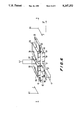
- FIG. 6 is a perspective view of a fourth embodiment of a sensor according to the invention.
- FIG. 7 is a schematic view showing electrical connection of the sensor with exciting voltage.
- the sensor 10 is markedly larger in the z-direction, which, by definition, represents the direction of the polar axis, than in the two other (x-, y-) directions.
- the excitation of oscillations is effected via the electrodes 13, 14 on the y-surfaces, which are illustrated in FIG. 2 and via which the sensor 10 becomes a frequency-determining component of an oscillator circuit.
- the position of a plane is expressed in a known fashion by the direction of its normal period.
- the proportionality factors d 15 and d 31 , . . . in the relationships between electric and mechanical variables are designated as piezoelectric coefficients.
- the modulus of the Coriolis force K c is proportional to the modulus of the angular velocity ⁇ , while its direction as determined by the vector product V ⁇ changes in sign with the sense of rotation of the angular velocity ⁇ .
- the distance of the axis of rotation plays no role in this regard.
- the velocity is given by the oscillatory motion produced by the alternating electric field E y , so that the velocity vector v, as illustrated in FIG. 1, extends parallel to the z-axis.
- the amplitude of the velocity which is determined by the product of the amplitude of oscillation and the oscillation frequency, can assume satisfactory values even in the case of shear oscillations with very small amplitudes of the order of magnitude of micrometers, since the frequency can be rendered correspondingly high.
- the frequency spacing With the use of a high oscillation frequency, e.g. 160 kHz, the oscillation frequency also being the signal frequency at the same time, the frequency spacing becomes much larger with respect to interference signals, which arise from vibrations, than in the case of known processes. As a consequence of the reduction, which is thereby possible, in the interference signals with a high-pass filter, there is a lower sensitivity to vibration.
- the orientation of the z-axis to the angular velocity vector ⁇ which is to be measured is to be chosen in this regard such that the ..periodic mechanical stresses on the z-surfaces causes by the Coriolis forces K c , generate periodic charges as a consequence of the piezoelectric characteristics. These charges then represent a measure of the angular velocity.
- the angular velocity vector ⁇ must be oriented parallel to the x-axis.
- the components of the angular velocity vector ⁇ produce no Coriolis forces at all, since the angular velocity vector ⁇ z is oriented parallel to the motion v of the oscillating masses. If, e.g. in the case of a motor vehicle driving in a curve, the angular velocity is measured about the vertical axis of the vehicle, the x-axis of the sensor 10 extends parallel to this axis.
- the output signal proportional to the angular velocity ⁇ is obtained by phase-sensitive rectification from the filtered and amplified signal at the signal electrodes 15, 16 of the sensor 10. Since the phase angle of the periodic recharging of the z-electrodes varies by 180° with reversal of the direction of rotation, the sign of the direct voltage specifies the sense of rotation.
- FIG. 3 An illustrative embodiment of the design of the sensor 10 is represented in FIG. 3.
- the sensor 10 is suspended in a frame 17 with the aid of contact springs 18.
- the contact springs 18 serve both for the elastic suspension of the sensor 10 in the frame 17, and the transmission of the electric measuring signal or of the electric exciting signal to the corresponding electrodes of the sensor 10. If the angular velocity of a rotation is to be measured about a vertical axis, the frame 17 of the sensor 10 is to be installed horizontally in the rotated total system.
- Suitable as contact springs 18 is any resilient body which does not essentially hamper the shear oscillations of the sensor 10, and which simultaneously assumes the electrical contacting through its own conductivity, or metallization, or in combination with thin wires.
- FIG. 4 A higher temporal resolution of the measuring signal is achieved with the illustrative embodiment represented in FIG. 4, in which the sensor 10 is held two pressure plates 21, 22.
- two longitudinal grooves 34 into which the knife-edges of the pressure plates 21, 22 are inserted, are constructed in the nodal line of the sensor 10, extending in the z-direction in the x-surfaces.
- the pressure plates 21, 22 it is also conceivable for the pressure plates 21, 22 to be applied to the x-surfaces of the sensor 10 without longitudinal grooves having been provided.
- the shear stresses thereby produced generate no charges on the signal electrodes of the z-surfaces, but charges are generated by all normal voltage components X x , Y y , Z z .
- the magnitude of the charges thereby generated can be very much larger than the measuring signal at the required detection limit.
- virtually the same mechanical shear stresses act through the mounting 25 on the two sensor plates 11, 12 with parallel z-axes, as represented in FIG. 5, the interference charges, generated by said vibrations, on the signal electrodes 15, 16 of the two plates 11, 12 are equally large.
- the signals are also added together if the oscillations of the two plates 11, 12 are excited in antiphase, as shown in the illustrated embodiment according to FIG. 5.
- compressive stresses arise in one sensor plate 11, while tensile stresses are produced in the other, or vice versa. This holds in all orientations for all types of force, which arise as a consequence of linear vibrations and rotary oscillations, i.e. for accelerating, centrifugal and Coriolis forces.
- FIG. 6 An increase in the output signal and compensation for interference effects is also possible with the an arrangement according to FIG. 6, which largely corresponds to that according to FIG. 5.
- four piezoelectric plates 31 to 34 which are firmly connected to a substrate 35, are used instead of the ⁇ /2 oscillator.
- the plates 31 and 34 therefore represent a ⁇ /4 oscillator.
- the result of this is a very compact and stable arrangement.
- the plates 31 and 34 can, e.g. be soldered onto a metal plate, or be affixed to a ceramic substrate with a conductive adhesive.
- the metal plate or the conductive adhesive then serves the purpose of excitation as one of the electrodes 13 or 14.
- the z-axis of the plates 31 to 34 i.e.
- the y-electrodes 36 to 39 of the sensors plates 31 to 34 are connected with a transformer 39 to the voltage source, as represented in FIG. 7.
- the charges generated on the z-electrodes of one side, e.g. 41 to 44 in FIG. 6, by the rotation of the sensor about the x-axis have the same sign, so that the four z-electrodes of each side can be interconnected, as is also represented for the z-electrodes 41 to 44.
- the low-frequency interferences are then largely compensated, while the useful signals are added together.
- interference voltages which must be compensated as effectively as possible, although they are not in phase with the signal, occur at the signal output even without rotation of the sensor. They are partly determined by unavoidable capacitancies between the excitation electrodes and the leads and the signal electrodes. Interference signals, which are due to piezoelectric secondary effects of the stray fields between the excitation and signal electrodes, are superposed. A component voltage of suitable magnitude and phase angle, which is superposed at the signal output of the sensor plates, is formed from the excitation voltage for the purpose of compensation. Furthermore, a harmonic signal occurs in the case of sensors with freely oscillating plates (FIGS.
- the magnitude of the measuring signal depends on the amplitude of oscillation of the sensors 10, said amplitude must be held constant. This can be done most reliably over a lengthy period by measuring the amplitude of oscillation.
- the above-mentioned harmonic signal clearly depends upon the amplitude of oscillation, and is consequently suitable for control.
- the exciting voltage is controlled in such a way that a predetermined value of the harmonic signal is held constant.
- a harmonic signal should be tapped in the signal path before filtering.
- the use of the harmonic signal has the advantage that the measurement of the amplitude of oscillation requires no additional sensors or electrodes, and that a corruption of the control signal by leakage of the much larger exciting voltage is virtually excluded because of the possibility of filtering.
- additional small electrodes 45, 46 are to be applied on the y-surfaces for this measurement of the amplitude of oscillation.
Landscapes
- Physics & Mathematics (AREA)
- Engineering & Computer Science (AREA)
- General Physics & Mathematics (AREA)
- Radar, Positioning & Navigation (AREA)
- Remote Sensing (AREA)
- Gyroscopes (AREA)
Applications Claiming Priority (2)
| Application Number | Priority Date | Filing Date | Title |
|---|---|---|---|
| DE3843143A DE3843143A1 (de) | 1988-12-22 | 1988-12-22 | Sensor zur bestimmung der winkelgeschwindigkeit |
| DE3843143 | 1988-12-22 |
Publications (1)
| Publication Number | Publication Date |
|---|---|
| US5247252A true US5247252A (en) | 1993-09-21 |
Family
ID=6369782
Family Applications (1)
| Application Number | Title | Priority Date | Filing Date |
|---|---|---|---|
| US07/646,605 Expired - Fee Related US5247252A (en) | 1988-12-22 | 1989-09-16 | Sensor for determining angular velocity with piezoceramic component formed as thickness shear oscillator |
Country Status (7)
| Country | Link |
|---|---|
| US (1) | US5247252A (de) |
| EP (1) | EP0449836B1 (de) |
| JP (1) | JPH04502202A (de) |
| KR (1) | KR910700466A (de) |
| BR (1) | BR8907844A (de) |
| DE (2) | DE3843143A1 (de) |
| WO (1) | WO1990007124A1 (de) |
Cited By (9)
| Publication number | Priority date | Publication date | Assignee | Title |
|---|---|---|---|---|
| US5767405A (en) | 1992-04-07 | 1998-06-16 | The Charles Stark Draper Laboratory, Inc. | Comb-drive micromechanical tuning fork gyroscope with piezoelectric readout |
| EP1201373A3 (de) * | 2000-10-19 | 2006-05-03 | HILTI Aktiengesellschaft | Sicherheitsschaltung für drehendes Elektrohandwerkzeuggerät |
| US20070186652A1 (en) * | 2004-03-12 | 2007-08-16 | Hotelling Steven P | Digital electronics on suspended assembly |
| US7539348B2 (en) | 2001-05-01 | 2009-05-26 | Panasonic Corporation | Digital map shape vector encoding method and position information transfer method |
| US8078563B2 (en) | 1999-08-27 | 2011-12-13 | Panasonic Corporation | Method for locating road shapes using erroneous map data |
| US8185306B2 (en) | 2001-01-29 | 2012-05-22 | Panasonic Corporation | Method and apparatus for transmitting position information on a digital map |
| US8219314B2 (en) | 1999-07-28 | 2012-07-10 | Panasonic Corporation | Method for transmitting location information on a digital map, apparatus for implementing the method and traffic information provision/reception system |
| US8655580B2 (en) | 2000-12-08 | 2014-02-18 | Panasonic Corporation | Method for transmitting information on position on digital map and device used for the same |
| CN105807085A (zh) * | 2016-03-15 | 2016-07-27 | 西安交通大学 | 一种基于压电特性和静电感应的轴承转动测量装置 |
Families Citing this family (6)
| Publication number | Priority date | Publication date | Assignee | Title |
|---|---|---|---|---|
| DE4135369A1 (de) * | 1991-10-26 | 1993-05-13 | Bosch Gmbh Robert | Testbarer piezoelektrischer beschleunigungssensor |
| JPH07113644A (ja) * | 1993-10-19 | 1995-05-02 | Shimada Phys & Chem Ind Co Ltd | 振動ジャイロ及びその駆動方法 |
| DE4431232C2 (de) * | 1994-09-02 | 1999-07-08 | Hahn Schickard Ges | Integrierbares Feder-Masse-System |
| JP3189620B2 (ja) * | 1995-04-12 | 2001-07-16 | 株式会社村田製作所 | 圧電振動子 |
| DE10026119B4 (de) * | 1999-05-26 | 2005-08-18 | Deutsches Zentrum für Luft- und Raumfahrt e.V. | Elastische Anordnung |
| JP4536016B2 (ja) * | 2006-02-03 | 2010-09-01 | 日本航空電子工業株式会社 | 振動ジャイロ |
Citations (1)
| Publication number | Priority date | Publication date | Assignee | Title |
|---|---|---|---|---|
| US3842681A (en) * | 1973-07-19 | 1974-10-22 | Sperry Rand Corp | Angular rate sensor |
Family Cites Families (5)
| Publication number | Priority date | Publication date | Assignee | Title |
|---|---|---|---|---|
| US3258617A (en) * | 1963-02-07 | 1966-06-28 | Avco Corp | Piezoelectric device |
| US3520195A (en) * | 1965-10-11 | 1970-07-14 | Gen Electric | Solid state angular velocity sensing device |
| AU554302B2 (en) * | 1983-09-02 | 1986-08-14 | Sundstrand Data Control, Inc. | Angular rate sensor utilizing parallel vibrating accelerometers |
| CA1217648A (en) * | 1984-01-23 | 1987-02-10 | Robert E. Stewart | Single axis multisensor |
| US4601205A (en) * | 1984-11-19 | 1986-07-22 | The Singer Company | Linear acceleration compensation for multisensor |
-
1988
- 1988-12-22 DE DE3843143A patent/DE3843143A1/de not_active Ceased
-
1989
- 1989-09-16 BR BR898907844A patent/BR8907844A/pt not_active IP Right Cessation
- 1989-09-16 US US07/646,605 patent/US5247252A/en not_active Expired - Fee Related
- 1989-09-16 WO PCT/DE1989/000592 patent/WO1990007124A1/de not_active Ceased
- 1989-09-16 EP EP89910065A patent/EP0449836B1/de not_active Expired - Lifetime
- 1989-09-16 KR KR1019900701813A patent/KR910700466A/ko not_active Ceased
- 1989-09-16 DE DE8989910065T patent/DE58903552D1/de not_active Expired - Fee Related
- 1989-09-16 JP JP1509295A patent/JPH04502202A/ja active Pending
Patent Citations (1)
| Publication number | Priority date | Publication date | Assignee | Title |
|---|---|---|---|---|
| US3842681A (en) * | 1973-07-19 | 1974-10-22 | Sperry Rand Corp | Angular rate sensor |
Cited By (10)
| Publication number | Priority date | Publication date | Assignee | Title |
|---|---|---|---|---|
| US5767405A (en) | 1992-04-07 | 1998-06-16 | The Charles Stark Draper Laboratory, Inc. | Comb-drive micromechanical tuning fork gyroscope with piezoelectric readout |
| US8219314B2 (en) | 1999-07-28 | 2012-07-10 | Panasonic Corporation | Method for transmitting location information on a digital map, apparatus for implementing the method and traffic information provision/reception system |
| US8078563B2 (en) | 1999-08-27 | 2011-12-13 | Panasonic Corporation | Method for locating road shapes using erroneous map data |
| EP1201373A3 (de) * | 2000-10-19 | 2006-05-03 | HILTI Aktiengesellschaft | Sicherheitsschaltung für drehendes Elektrohandwerkzeuggerät |
| US8655580B2 (en) | 2000-12-08 | 2014-02-18 | Panasonic Corporation | Method for transmitting information on position on digital map and device used for the same |
| US8185306B2 (en) | 2001-01-29 | 2012-05-22 | Panasonic Corporation | Method and apparatus for transmitting position information on a digital map |
| US7539348B2 (en) | 2001-05-01 | 2009-05-26 | Panasonic Corporation | Digital map shape vector encoding method and position information transfer method |
| US20070186652A1 (en) * | 2004-03-12 | 2007-08-16 | Hotelling Steven P | Digital electronics on suspended assembly |
| US7856878B2 (en) * | 2004-03-12 | 2010-12-28 | Thomson Licensing | Digital electronics on suspended assembly |
| CN105807085A (zh) * | 2016-03-15 | 2016-07-27 | 西安交通大学 | 一种基于压电特性和静电感应的轴承转动测量装置 |
Also Published As
| Publication number | Publication date |
|---|---|
| EP0449836B1 (de) | 1993-02-10 |
| KR910700466A (ko) | 1991-03-15 |
| WO1990007124A1 (de) | 1990-06-28 |
| JPH04502202A (ja) | 1992-04-16 |
| DE58903552D1 (de) | 1993-03-25 |
| BR8907844A (pt) | 1991-10-08 |
| DE3843143A1 (de) | 1990-06-28 |
| EP0449836A1 (de) | 1991-10-09 |
Similar Documents
| Publication | Publication Date | Title |
|---|---|---|
| US6227048B1 (en) | Vibrators, vibratory gyroscopes, devices for measuring a linear acceleration and a method of measuring a turning angular rate | |
| US4750364A (en) | Angular velocity and acceleration sensor | |
| US7004024B1 (en) | Horizontal and tuning fork vibratory microgyroscope | |
| US4899587A (en) | Method for sensing rotation using vibrating piezoelectric elements | |
| US5247252A (en) | Sensor for determining angular velocity with piezoceramic component formed as thickness shear oscillator | |
| USRE33479E (en) | Vibratory angular rate sensing system | |
| US6346765B1 (en) | Vibrator, vibratory gyroscope, and vibrator adjusting method | |
| US6125701A (en) | Angular velocity detecting apparatus | |
| US6747393B2 (en) | Vibrator, vibratory gyroscope, and vibration adjusting method | |
| JP4702942B2 (ja) | 振動ジャイロ用素子及び振動ジャイロ | |
| JPH08334330A (ja) | 波動ジャイロスコープ及びそれを用いた回転角速度検出方法 | |
| JPH09126783A (ja) | 圧電振動ジャイロ | |
| US6437483B2 (en) | Vibrator, vibratory gyroscope, and vibration adjusting method | |
| JPH08152328A (ja) | 角速度センサ及びその使用方法 | |
| KR100254114B1 (ko) | 2축 동시 측정용 압전 회전 센서 및 그 측정 회로 | |
| WO2006075764A1 (ja) | 振動型ジャイロスコープ | |
| KR100494967B1 (ko) | 에너지-트래핑진동모드를이용하는압전진동성자이로스코프 | |
| KR100203315B1 (ko) | 2축 내비게이션 그레이드 마이크로머신드 회전 센서 시스템 | |
| JP2001208545A (ja) | 圧電振動ジャイロスコープ | |
| JP3028999B2 (ja) | 振動ジャイロ | |
| RU2119645C1 (ru) | Датчик инерциальной первичной информации | |
| JPH08178669A (ja) | 振動型角速度センサ | |
| JPH06281465A (ja) | 弾性表面波ジャイロスコープ | |
| JP2000213940A (ja) | 圧電ジャイロ、圧電ジャイロの駆動方法、圧電ジャイロの検出方法及び圧電ジャイロの機械結合の評価方法 | |
| Tamura et al. | Triaxial quartz gyrosensor using a threefold rotatory symmetric form vibrator |
Legal Events
| Date | Code | Title | Description |
|---|---|---|---|
| AS | Assignment |
Owner name: ROBERT BOSCH GMBH A LIMITED LIABILITY COMPANY O Free format text: ASSIGNMENT OF ASSIGNORS INTEREST.;ASSIGNORS:HAMISCH, HANSJOACHIM;KAISER, HANS-JURGEN;BORUSCHEWITZ, MANFRED;REEL/FRAME:005867/0126;SIGNING DATES FROM 19901116 TO 19910120 |
|
| REMI | Maintenance fee reminder mailed | ||
| LAPS | Lapse for failure to pay maintenance fees | ||
| FP | Lapsed due to failure to pay maintenance fee |
Effective date: 19970924 |
|
| STCH | Information on status: patent discontinuation |
Free format text: PATENT EXPIRED DUE TO NONPAYMENT OF MAINTENANCE FEES UNDER 37 CFR 1.362 |