US5232197A - Control device - Google Patents
Control device Download PDFInfo
- Publication number
- US5232197A US5232197A US07/910,304 US91030492A US5232197A US 5232197 A US5232197 A US 5232197A US 91030492 A US91030492 A US 91030492A US 5232197 A US5232197 A US 5232197A
- Authority
- US
- United States
- Prior art keywords
- rotor
- rotary valve
- accordance
- actuator housing
- housing
- Prior art date
- Legal status (The legal status is an assumption and is not a legal conclusion. Google has not performed a legal analysis and makes no representation as to the accuracy of the status listed.)
- Expired - Fee Related
Links
- 238000004804 winding Methods 0.000 claims abstract description 15
- 238000002485 combustion reaction Methods 0.000 claims abstract description 5
- 230000001154 acute effect Effects 0.000 claims abstract description 4
- 210000000078 claw Anatomy 0.000 claims description 15
- 238000001746 injection moulding Methods 0.000 claims description 4
- XAGFODPZIPBFFR-UHFFFAOYSA-N aluminium Chemical compound [Al] XAGFODPZIPBFFR-UHFFFAOYSA-N 0.000 claims description 2
- 229910052782 aluminium Inorganic materials 0.000 claims description 2
- 230000001105 regulatory effect Effects 0.000 claims description 2
- 238000010276 construction Methods 0.000 claims 2
- 230000001276 controlling effect Effects 0.000 claims 1
- 230000000149 penetrating effect Effects 0.000 claims 1
- 238000000429 assembly Methods 0.000 abstract description 2
- 230000006698 induction Effects 0.000 description 6
- 238000002347 injection Methods 0.000 description 2
- 239000007924 injection Substances 0.000 description 2
- 238000004519 manufacturing process Methods 0.000 description 2
- 230000004075 alteration Effects 0.000 description 1
- 239000004411 aluminium Substances 0.000 description 1
- 230000015572 biosynthetic process Effects 0.000 description 1
- 238000002788 crimping Methods 0.000 description 1
- 238000005516 engineering process Methods 0.000 description 1
- 238000001125 extrusion Methods 0.000 description 1
- 238000000034 method Methods 0.000 description 1
- 238000012986 modification Methods 0.000 description 1
- 230000004048 modification Effects 0.000 description 1
- 238000000465 moulding Methods 0.000 description 1
- 238000010137 moulding (plastic) Methods 0.000 description 1
- 239000006223 plastic coating Substances 0.000 description 1
- 239000000243 solution Substances 0.000 description 1
- 238000003466 welding Methods 0.000 description 1
Images


Classifications
-
- F—MECHANICAL ENGINEERING; LIGHTING; HEATING; WEAPONS; BLASTING
- F02—COMBUSTION ENGINES; HOT-GAS OR COMBUSTION-PRODUCT ENGINE PLANTS
- F02M—SUPPLYING COMBUSTION ENGINES IN GENERAL WITH COMBUSTIBLE MIXTURES OR CONSTITUENTS THEREOF
- F02M3/00—Idling devices for carburettors
- F02M3/06—Increasing idling speed
- F02M3/07—Increasing idling speed by positioning the throttle flap stop, or by changing the fuel flow cross-sectional area, by electrical, electromechanical or electropneumatic means, according to engine speed
-
- F—MECHANICAL ENGINEERING; LIGHTING; HEATING; WEAPONS; BLASTING
- F02—COMBUSTION ENGINES; HOT-GAS OR COMBUSTION-PRODUCT ENGINE PLANTS
- F02D—CONTROLLING COMBUSTION ENGINES
- F02D9/00—Controlling engines by throttling air or fuel-and-air induction conduits or exhaust conduits
- F02D9/08—Throttle valves specially adapted therefor; Arrangements of such valves in conduits
- F02D9/12—Throttle valves specially adapted therefor; Arrangements of such valves in conduits having slidably-mounted valve members; having valve members movable longitudinally of conduit
- F02D9/16—Throttle valves specially adapted therefor; Arrangements of such valves in conduits having slidably-mounted valve members; having valve members movable longitudinally of conduit the members being rotatable
-
- F—MECHANICAL ENGINEERING; LIGHTING; HEATING; WEAPONS; BLASTING
- F16—ENGINEERING ELEMENTS AND UNITS; GENERAL MEASURES FOR PRODUCING AND MAINTAINING EFFECTIVE FUNCTIONING OF MACHINES OR INSTALLATIONS; THERMAL INSULATION IN GENERAL
- F16K—VALVES; TAPS; COCKS; ACTUATING-FLOATS; DEVICES FOR VENTING OR AERATING
- F16K31/00—Actuating devices; Operating means; Releasing devices
- F16K31/02—Actuating devices; Operating means; Releasing devices electric; magnetic
- F16K31/06—Actuating devices; Operating means; Releasing devices electric; magnetic using a magnet, e.g. diaphragm valves, cutting off by means of a liquid
- F16K31/0682—Actuating devices; Operating means; Releasing devices electric; magnetic using a magnet, e.g. diaphragm valves, cutting off by means of a liquid with an articulated or pivot armature
-
- F—MECHANICAL ENGINEERING; LIGHTING; HEATING; WEAPONS; BLASTING
- F02—COMBUSTION ENGINES; HOT-GAS OR COMBUSTION-PRODUCT ENGINE PLANTS
- F02M—SUPPLYING COMBUSTION ENGINES IN GENERAL WITH COMBUSTIBLE MIXTURES OR CONSTITUENTS THEREOF
- F02M3/00—Idling devices for carburettors
- F02M3/06—Increasing idling speed
- F02M2003/067—Increasing idling speed the valve for controlling the cross-section of the conduit being rotatable, but not being a screw-like valve
Definitions
- the invention is based on a control device for regulating the opening of a cross sectional area of a flow line, in particular for internal combustion engines.
- the two-part drive housing comprises a hollow cylinder which is pushed onto and fixed to the stub, and a cap which closes off the hollow cylinder on the front face, this cap being equipped with a plug which is connected to the armature winding.
- the stator held on the hollow cylinder has two permanent magnet poles, whilst the rotor carries the armature winding in axial grooves.
- the armature comprises two windings set at 90° to each other and acting in opposite directions, with these windings being connected with the plug via slip rings.
- the rotor together with the rotary valve, is fitted torsionally rigid on a bearing sleeve which is supported via two radial bearings located at an axial distance from one another on the rotor axis, which in turn is held in the two locating apertures of the boss formed on the actuator housing on the one side, and on the cap of the drive housing on the other side.
- the control part of the rotary valve which projects into the setting chamber of the actuator housing and there acts in conjunction with the setting window, and which has an arc-shaped cross section, is located coaxially to the rotor axis.
- the known control device comprises a total of three subassemblies which are manufactured separately and which permit simple final assembly; namely the actuator housing with an actuator chamber and boss, the bearing sleeve onto which are fixed the rotor with the rotor winding, rotary valve and slip rings, and the drive housing with stator, connector plug and boss.
- the actuator housing with an actuator chamber and boss
- the drive housing with stator, connector plug and boss.
- control device in accordance with this invention has an advantage that it is possible to optionally set the air gap at the setting window, in a simple manner.
- the thickness of the spacing disc between the front faces of the bosses on the actuator housing and the fixing part of the rotary valve, which is connected torsionally rigid to the rotor, is of decisive importance for the air gap size. Close tolerance limits in manufacture are thus no longer necessary.
- the precondition is at the same time provided for combining the control device; which comprises three functional units, namely the actuator housing, the rotor with the rotary valve, and the drive housing with the stator; with one another in a type of a module system, and for example, using modified functional units adapted to the respective technical requirements, such as an actuator housing with flow channel which is elongated, angled-off, or rotated about 180°, or actuating drives of different designs.
- the required clearance between the rotary valve and setting window is ensured in each case by appropriately selecting the thickness of the spacing disk.
- the drive housing After setting the axial clearance of the rotor with an appropriate spacing disk between the front faces of the rotor at one end and of the coaxial boss formed on the drive housing at the other end, the drive housing is connected inseparably with the actuator housing at the stub.
- the rotor and the fixing part of the rotary valve is held, torsionally rigid, on a rotor shaft which is carried in radial bearings, which in turn are located in the locating apertures of the bosses formed on the actuator housing and drive housing.
- the rotor is fixed on a bearing sleeve, which is of one piece with the fixing part of the rotary valve.
- the bearing sleeve is supported on an axis via two radial bearings located at an axial distance, with this axis being held in the two locating apertures of the bosses formed on the actuator housing and drive housing.
- the axis is pressed into the locating aperture of the boss formed on the actuator housing, and after the assembly of the drive housing it projects into the other locating aperture of the boss formed on the drive housing.
- the rotary valve is preferably manufactured of plastic, with the formation of the bearing bush and the fixing of the rotor being effected by plastic extrusion during the injection moulding.
- FIGS. 1 and 2 show respectively a longitudinal cross-section of a control device in accordance with a first and second design example
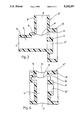
- FIGS. 3 and 4 show respectively a longitudinal cross-section of a modified actuator housing of the control device in FIG. 1, in accordance with the two design examples.
- the control device shown in longitudinal cross-section in FIG. 1 serves to control the opening of the cross-sectional area of a bypass duct 10 around a schematically represented throttle valve 11 in the induction pipe 12 of an internal combustion engine for the purpose of idling speed control.
- the control device has an actuator housing (13) of plastic, in which are formed a flow channel 14 and a setting chamber 15, which is penetrated by the flow channel 14.
- the flow channel 14 ends in an inlet port 16 and an outlet port 17, in an inlet connection stub 18 or an outlet connection stub 19.
- the connection of the flow channel 14 to the induction pipe 12 of the internal combustion engine is via hose connectors which are pushed onto the inlet stub 18 and the outlet stub 19.
- a hollow cylindrical stub 20 Projecting from the actuator housing 13, at right angles to the housing axis, is a hollow cylindrical stub 20, which coaxially encompasses boss 21 with a coaxial locating aperture 22 with radial clearance.
- an arc-shaped slot 23 is provided in the wall of the actuator housing 13.
- a setting window 24 is formed in the direction of the flow channel 14, which lies on a plane formed by a portion of the envelope of a cone, and thus extends in the longitudinal cross-section in accordance with FIG. 1, obliquely to the flow channel 14. With the axis of the boss 21, the plane of the setting window plane encompasses an acute angle.
- the opening of the setting window 24 is controlled by a rotary valve 25 which, with a cone-segment shaped control part 251, projects through the slot 23 into the setting chamber 15, and extends parallel to the setting window 24.
- the control part 251 changes to a ring-shaped fixing section 252, which fits torsionally rigid on a rotor shaft 26 of an actuating drive 27.
- the control part 251 is aligned in such a way that with the axis of the rotor shaft 26, it encloses the same acute angle as the setting window 24 with the axis of the boss 21.
- the actuating drive 27 for turning the rotary valve 25 consists of a stator 28 with stator winding 29 and a permanent magnet rotor 30 which is mounted torsionally rigid on the rotor shaft 26.
- the stator 28 is held on a cup-shaped drive housing 33, which with its open front face is pushed over the stub 20 and fixed there.
- a coaxial boss 31, with coaxial locating aperture 32, projects coaxially to the housing axis, at the base of the drive housing 33.
- a radial bearing 34 or 35 is located respectively, in which the rotor shaft 26 is held.
- a connector plug 36 is molded on in one piece, two plug contacts 37 of which are connected with the ends of the stator winding 29.
- the drive housing 33 is manufactured of plastic, with the connector plug 36 and the boss 31 being molded on in one piece.
- the stator 28 has two claw poles 38, 39, offset at 180° to one another in the circumferential direction, which are connected at axially opposite front faces respectively with a ring casing 40 which encompasses the claw pole 38, 39 with radial clearance.
- the stator winding 29 is set as a toroid coil in the annular space formed by the ring casing 40 and the claw poles 38, 39.
- the two-pole permanent magnet rotor 30 consists of a hollow cylindrical permanent magnet 41 with diametric magnetisation direction, which is fixed on the rotor shaft by means of plastic molding. When molding the rotary valve 25, which is manufactured of plastic, the rotor shaft and the hollow cylindrical permanent magnet 41 are also placed in the injection mold so that the plastic-coating of rotor shaft 26 and magnet 41 takes place simultaneously.
- the control device described above consists of three functional units, namely of the actuator housing 13 to be connected to the induction pipe, the rotor 30 with rotor shaft 26 and rotary valve 25, and the drive housing 33 with stator 28 and stator winding 29.
- a spacing disk 42 is inserted between the front face of the boss 21 formed on the actuator housing 13, and the opposite front face of the fixing part 252 of the rotary valve 25.
- the axial thickness of this spacing disk 42 must be of such dimensions that a desired air gap is set between the cone-segment-shaped control part 251 of the rotary valve 25 and the setting window 24 lying in a cone envelope plane, with this air gap ensuring on the one hand sufficient clearance for the rotation of the rotary valve 25, and on the other hand sufficient coverage of the setting window 24 by the rotary valve 25.
- the permitted axial clearance of the rotor 30 in the radial bearings 34, 35 is determined by an spacing disk 43 which lies between the front face of the boss 31 formed on the drive housing 33, and the front face of the rotor 30.
- the axial thickness of the spacing disk 43 determines the possible axial clearance of the rotor 30.
- the rotary valve 25 (defined opening cross section in the setting window with currentless actuating drive) by turning the actuator housing 13 and the drive housing 33 towards one another, the latter is inseparably connected, e.g. by laser welding, adhesion, crimping etc., with the stub 20.
- actuator housings 13 of different designs can be used on the unmodified actuator drive 27, which through their varying designs fulfill the specific technical requirements in individual cases.
- Examples of such modified actuator housings are shown in longitudinal section in FIGS. 3 and 4.
- the flow channel 14 is turned around a right angle, so that the inlet stub 18 and the outlet stub 19 are set at right angles to one another.
- the locating aperture 22' in the boss 21 is designed as a straight-through drilled hole, and not as a blind bore as in FIG. 1.
- This actuator housing 13 can be easily connected with the two other functional units of drive housing 33 with stator 28 and stator winding 29, and rotor 30 with rotary valve 25. Through appropriate selection of the spacing disk 42, the air gap between the control part 251 of the rotary valve 25 and the setting window 24 is set.
- the actuator housing 13" in FIG. 4 is suitable for a so-called integrated solution, in which the actuator housing 13" is set in a bypass duct formed on the induction pipe.
- inletand outlet stubs 18 and 19 are not longer required, nor are the connection tubes to the induction stub.
- the control device shown in longitudinal cross-section in FIG. 2 is slightly modified vis-a-vis the control device described above in relation to FIG. 1.
- the alteration comprises the rotor 30, once again designed as a hollow cylindrical permanent magnet 41 with diametric magnetisation direction, located on a bearing sleeve 44 which is of one piece with the rotary valve 25, and the bearing shell 44 being supported on an shaft 47 via two radial bearings 45, 46 located at an axial distance from one another, with this shaft in turn being pressed into the locating aperture 22 in the boss 21 formed on the actuator housing 13.
- the free end of the shaft 46 enters fully into the locating aperture 22 of the boss 31 formed on the drive housing 33.
- the two radial bearings 45, 46 are held in grooves 48, 49 of the bearing sleeve 44.
- the rotary valve 25 is once again manufactured of plastic, and during the injection process the bearing sleeve 44 is molded on at the same time, and the permanent magnet 41 is fixed on the bearing sleeve 44 by means of plastic injection molding.
- control device in FIG. 2 is the same as the control device described for FIG. 1, so that the same components are marked with the same reference numbers.
- the invention is not restricted to the design example described above.
- the actuator housing 13, the rotary valve 25 and the drive housing 33 can also be manufactured of aluminium instead of plastic.
Landscapes
- Engineering & Computer Science (AREA)
- General Engineering & Computer Science (AREA)
- Mechanical Engineering (AREA)
- Chemical & Material Sciences (AREA)
- Combustion & Propulsion (AREA)
- Control Of Throttle Valves Provided In The Intake System Or In The Exhaust System (AREA)
- Magnetically Actuated Valves (AREA)
- Electrically Driven Valve-Operating Means (AREA)
- Laminated Bodies (AREA)
- Adhesive Tapes (AREA)
Applications Claiming Priority (2)
| Application Number | Priority Date | Filing Date | Title |
|---|---|---|---|
| DE4038762A DE4038762A1 (de) | 1990-12-05 | 1990-12-05 | Stelleinrichtung |
| JP2-4038762 | 1990-12-05 |
Publications (1)
| Publication Number | Publication Date |
|---|---|
| US5232197A true US5232197A (en) | 1993-08-03 |
Family
ID=6419635
Family Applications (1)
| Application Number | Title | Priority Date | Filing Date |
|---|---|---|---|
| US07/910,304 Expired - Fee Related US5232197A (en) | 1990-12-05 | 1991-11-15 | Control device |
Country Status (6)
| Country | Link |
|---|---|
| US (1) | US5232197A (de) |
| EP (1) | EP0513274A1 (de) |
| JP (1) | JP3181587B2 (de) |
| KR (1) | KR100234862B1 (de) |
| DE (1) | DE4038762A1 (de) |
| WO (1) | WO1992010662A1 (de) |
Cited By (3)
| Publication number | Priority date | Publication date | Assignee | Title |
|---|---|---|---|---|
| US20030089870A1 (en) * | 2000-10-04 | 2003-05-15 | Klaus Borasch | Throttle-valve actuating unit |
| US8641153B2 (en) | 2007-03-10 | 2014-02-04 | Continental Teves Ag & Co. Ohg | Valve assembly |
| CN104141565A (zh) * | 2014-07-29 | 2014-11-12 | 长城汽车股份有限公司 | 可变进气歧管、发动机和车辆 |
Families Citing this family (2)
| Publication number | Priority date | Publication date | Assignee | Title |
|---|---|---|---|---|
| DE19932747B4 (de) * | 1998-10-05 | 2010-07-01 | Robert Bosch Gmbh | Verfahren zur Herstellung eines Druckregelventils für ein Automatikgetriebe eines Kraftfahrzeuges und nach dem Verfahren hergestelltes Druckregelventil |
| DE10119281A1 (de) * | 2001-04-20 | 2002-10-24 | Mann & Hummel Filter | Schaltverband zum Verschluss von Saugkanälen einer Ansaugvorrichtung mit diesem Schaltverband |
Citations (5)
| Publication number | Priority date | Publication date | Assignee | Title |
|---|---|---|---|---|
| GB853396A (en) * | 1957-12-26 | 1960-11-09 | Jean Faure Herman | Improvements in electromagnetic fluid control valves |
| DE3313830A1 (de) * | 1983-04-16 | 1984-11-08 | Robert Bosch Gmbh, 7000 Stuttgart | Verfahren und vorrichtung zur steuerung mindestens eines drosselquerschnittes in einer steuerleitung |
| US4494517A (en) * | 1982-09-17 | 1985-01-22 | Robert Bosch Gmbh | Method and apparatus for controlling at least one throttle cross section in a control line |
| DE8805211U1 (de) * | 1988-04-20 | 1989-08-17 | Robert Bosch Gmbh, 7000 Stuttgart | Vorrichtung zur Regelung der Leerlaufdrehzahl einer Brennkraftmaschine |
| US4895344A (en) * | 1987-08-27 | 1990-01-23 | Robert Bosch Gmbh | Electric control motor |
-
1990
- 1990-12-05 DE DE4038762A patent/DE4038762A1/de not_active Withdrawn
-
1991
- 1991-11-15 JP JP51809291A patent/JP3181587B2/ja not_active Expired - Fee Related
- 1991-11-15 EP EP91920078A patent/EP0513274A1/de not_active Withdrawn
- 1991-11-15 KR KR1019920701864A patent/KR100234862B1/ko not_active IP Right Cessation
- 1991-11-15 US US07/910,304 patent/US5232197A/en not_active Expired - Fee Related
- 1991-11-15 WO PCT/DE1991/000893 patent/WO1992010662A1/de not_active Application Discontinuation
Patent Citations (5)
| Publication number | Priority date | Publication date | Assignee | Title |
|---|---|---|---|---|
| GB853396A (en) * | 1957-12-26 | 1960-11-09 | Jean Faure Herman | Improvements in electromagnetic fluid control valves |
| US4494517A (en) * | 1982-09-17 | 1985-01-22 | Robert Bosch Gmbh | Method and apparatus for controlling at least one throttle cross section in a control line |
| DE3313830A1 (de) * | 1983-04-16 | 1984-11-08 | Robert Bosch Gmbh, 7000 Stuttgart | Verfahren und vorrichtung zur steuerung mindestens eines drosselquerschnittes in einer steuerleitung |
| US4895344A (en) * | 1987-08-27 | 1990-01-23 | Robert Bosch Gmbh | Electric control motor |
| DE8805211U1 (de) * | 1988-04-20 | 1989-08-17 | Robert Bosch Gmbh, 7000 Stuttgart | Vorrichtung zur Regelung der Leerlaufdrehzahl einer Brennkraftmaschine |
Cited By (4)
| Publication number | Priority date | Publication date | Assignee | Title |
|---|---|---|---|---|
| US20030089870A1 (en) * | 2000-10-04 | 2003-05-15 | Klaus Borasch | Throttle-valve actuating unit |
| US6886806B2 (en) * | 2000-10-04 | 2005-05-03 | Robert Bosch Gmbh | Throttle-valve actuating unit |
| US8641153B2 (en) | 2007-03-10 | 2014-02-04 | Continental Teves Ag & Co. Ohg | Valve assembly |
| CN104141565A (zh) * | 2014-07-29 | 2014-11-12 | 长城汽车股份有限公司 | 可变进气歧管、发动机和车辆 |
Also Published As
| Publication number | Publication date |
|---|---|
| JPH05503136A (ja) | 1993-05-27 |
| DE4038762A1 (de) | 1992-06-11 |
| KR100234862B1 (ko) | 2000-01-15 |
| JP3181587B2 (ja) | 2001-07-03 |
| KR920703990A (ko) | 1992-12-18 |
| EP0513274A1 (de) | 1992-11-19 |
| WO1992010662A1 (de) | 1992-06-25 |
Similar Documents
| Publication | Publication Date | Title |
|---|---|---|
| US4480614A (en) | Idling speed control device of an internal combustion engine | |
| US5087847A (en) | Bearing retainer for electromagnetic rotating actuator | |
| US4723753A (en) | Flow rate control valve system | |
| US4412517A (en) | Idling speed control device of an internal combustion engine | |
| US4593222A (en) | Electric control motor | |
| JPS5929765A (ja) | 歯車ロ−タ型燃料ポンプ | |
| JP3007153B2 (ja) | 回転調節器 | |
| US4723754A (en) | Flow rate control valve system | |
| US4378767A (en) | Idling speed control device of an internal combustion engine | |
| JP2001303986A (ja) | 電動式スロットルバルブ組立体、トルクモータ組立体およびその製造方法 | |
| JP2766026B2 (ja) | スロツトルユニツトを有する制御装置 | |
| RU2070647C1 (ru) | Поворотный исполнительный орган холостого хода | |
| US4414942A (en) | Idling speed control device of an internal combustion engine | |
| US5232197A (en) | Control device | |
| JPH048618B2 (de) | ||
| JPH0243011B2 (de) | ||
| US5234192A (en) | Rotational control device | |
| JPH05500095A (ja) | 電磁式回転調整器 | |
| US4895344A (en) | Electric control motor | |
| JPH0211864A (ja) | 内燃機関のアイドリング回転数を調整するための装置 | |
| AU648461B2 (en) | Electromagnetic rotating actuator | |
| WO2015083690A1 (ja) | コアレスモータ駆動式スロットルバルブ装置 | |
| US5293144A (en) | Electric rotary actuator | |
| US4397275A (en) | Idling speed control device of an internal combustion engine | |
| CN202300660U (zh) | 用于节气门的致动器组件 |
Legal Events
| Date | Code | Title | Description |
|---|---|---|---|
| AS | Assignment |
Owner name: ROBERT BOSCH GMBH, A LIMITED LIABILITY COMPANY OF Free format text: ASSIGNMENT OF ASSIGNORS INTEREST.;ASSIGNORS:KALIPPKE, HARALD;FRANZ, MANFRED;RENNINGER, ERHARD;AND OTHERS;REEL/FRAME:006326/0486;SIGNING DATES FROM 19920203 TO 19920228 |
|
| FEPP | Fee payment procedure |
Free format text: PAYOR NUMBER ASSIGNED (ORIGINAL EVENT CODE: ASPN); ENTITY STATUS OF PATENT OWNER: LARGE ENTITY |
|
| FPAY | Fee payment |
Year of fee payment: 4 |
|
| FPAY | Fee payment |
Year of fee payment: 8 |
|
| REMI | Maintenance fee reminder mailed | ||
| LAPS | Lapse for failure to pay maintenance fees | ||
| STCH | Information on status: patent discontinuation |
Free format text: PATENT EXPIRED DUE TO NONPAYMENT OF MAINTENANCE FEES UNDER 37 CFR 1.362 |
|
| FP | Lapsed due to failure to pay maintenance fee |
Effective date: 20050803 |