US5165375A - Master piston for a compression release engine retarder - Google Patents
Master piston for a compression release engine retarder Download PDFInfo
- Publication number
- US5165375A US5165375A US07/816,663 US81666392A US5165375A US 5165375 A US5165375 A US 5165375A US 81666392 A US81666392 A US 81666392A US 5165375 A US5165375 A US 5165375A
- Authority
- US
- United States
- Prior art keywords
- master piston
- piston
- foot
- apparatus defined
- prestressed
- Prior art date
- Legal status (The legal status is an assumption and is not a legal conclusion. Google has not performed a legal analysis and makes no representation as to the accuracy of the status listed.)
- Expired - Lifetime
Links
- 230000006835 compression Effects 0.000 title claims abstract description 26
- 238000007906 compression Methods 0.000 title claims abstract description 26
- 230000014759 maintenance of location Effects 0.000 claims description 4
- 241000931526 Acer campestre Species 0.000 claims 1
- 238000004519 manufacturing process Methods 0.000 abstract description 15
- 238000009434 installation Methods 0.000 description 5
- 238000000034 method Methods 0.000 description 4
- 230000008569 process Effects 0.000 description 4
- 230000006872 improvement Effects 0.000 description 3
- 230000000712 assembly Effects 0.000 description 2
- 238000000429 assembly Methods 0.000 description 2
- 238000002485 combustion reaction Methods 0.000 description 1
- 238000001816 cooling Methods 0.000 description 1
- 238000003780 insertion Methods 0.000 description 1
- 230000037431 insertion Effects 0.000 description 1
- 238000012986 modification Methods 0.000 description 1
- 230000004048 modification Effects 0.000 description 1
- 230000000979 retarding effect Effects 0.000 description 1
- 238000007493 shaping process Methods 0.000 description 1
Images


Classifications
-
- F—MECHANICAL ENGINEERING; LIGHTING; HEATING; WEAPONS; BLASTING
- F01—MACHINES OR ENGINES IN GENERAL; ENGINE PLANTS IN GENERAL; STEAM ENGINES
- F01L—CYCLICALLY OPERATING VALVES FOR MACHINES OR ENGINES
- F01L13/00—Modifications of valve-gear to facilitate reversing, braking, starting, changing compression ratio, or other specific operations
- F01L13/06—Modifications of valve-gear to facilitate reversing, braking, starting, changing compression ratio, or other specific operations for braking
- F01L13/065—Compression release engine retarders of the "Jacobs Manufacturing" type
Definitions
- This invention relates to engine retarders of the compression release type. More particularly, the invention relates to an improved master piston for a compression release engine retarder.
- Engine retarders of the compression release type are well-known in the art. In general, such retarders are designed temporarily to convert an internal combustion engine into an air compressor so as to develop a retarding horsepower which may be a substantial portion of the operating horsepower normally developed by the engine in its powering mode.
- mast pistons have been complex assemblies that are costly to manufacture and are subject to wear and/or cause wear on the engine surface in contact with them.
- the rounded surface that makes contact with the pushrod or rocker arm is difficult and expensive to manufacture.
- the line contact between the master piston and the pushrod or rocker arm causes high stress at the contact line, which increases wear of the master piston and the pushrod or rocker arm.
- the prior art design of the return spring requires a hole to be bored into the piston for placement of the return spring, after which, the hole is closed with a threaded plug. The complex process required for the manufacture of the contact surface and the return spring cavity is very costly.
- the master piston contact region is separated from the master piston body and modified to provide automatic alignment between the master piston and the associated push rod or rocker arm, thereby eliminating the need for an anti-rotation pin. Additionally, the contact region is modified to provide increased contact area, thereby reducing contact stress between the master piston and the push rod or rocker arm.
- FIG. 1 is a simplified elevation view, partly in section, of a prior art master piston assembly.
- FIG. 2 is another view similar to FIG. 1 showing the apparatus of FIG. 1 rotated 90° about a vertical axis.
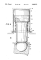
- FIG. 3 is a simplified elevation view, partly in section, of an illustrative embodiment of the invention before contact with a rocker arm or other mechanical input element.
- FIG. 4 is a view similar to FIG. 3 showing the apparatus of FIG. 3 after contact with a rocker arm or other mechanical input element.
- FIGS. 1 and 2 show a typical prior art master piston assembly 10, which comprises master piston body 2, threaded plug 1, balancing groove 3 (which tends to evenly distribute hydraulic pressure to keep master piston assembly 10 concentric in master piston cylinder 6), return spring 4 located within cavity 9 of master piston body 2, and anti-rotation pin 7.
- Master piston assembly 10 is shown in its condition when the engine brake is off and therefore return spring 4 alone controls the vertical position of body 2 in cylinder 6.
- Anti-rotation pin 7 provides three functions to master piston assembly 10, the first of which is to keep master piston assembly 10 within master piston cylinder 6. The second function of anti-rotation pin 7 is to prevent master piston assembly 10 from rotating within master piston cylinder 6.
- Contact surface 5 is a rounded surface that is difficult to manufacture and therefore expensive.
- the shaping of master piston body 2 to receive anti-rotation pin 7 in elongated slot 8 is also expensive, as is the process of boring master piston body 2 to create cavity 9 for insertion of return spring 4.
- Assembly of master piston assembly 10 requires that return spring 4 be inserted into cavity 9, followed by screwing threaded plug 1 into master piston body 2. This completed assembly is then inserted into master piston cylinder 6 and anti-rotation pin 7 must then be screwed through cylinder 6 and slot 8 into piston body 2. This relatively complex assembly process further increases manufacturing cost.
- rounded contact surface 5 makes a line contact with an associated push rod or rocker arm as mentioned above to receive engine timing inputs.
- Such a line contact provides a contact region between master piston assembly 10 and the associated push rod or rocker arm which is a relatively small area. This small contact area tends to promote wear of the master piston and/or the push rod or rocker arm.
- master piston assembly 20 comprises master piston body 12, return spring 14, and foot 23. Master piston assembly 20 is again shown in its condition when the engine brake is off so that the position of body 12 is determined entirely by return spring 14. Master piston body 12 comprises at one end piston head 15 having annular balancing groove 13 (which tends to evenly distribute hydraulic pressure to keep master piston assembly 20 concentric in master piston cylinder 16) and at the other end spherical ball joint 17.
- Return spring 14 is a prestressed compression coil spring having one end in annular channel 18 and the other end abutting washer 21 which is held in place by snap ring 22.
- Foot 23 is a cylindrical object with a closed end and an open end which can swivel on ball joint 17. (By "swivel” it is meant that foot 23 can both pivot and rotate with respect to ball joint 17.)
- the closed end of foot 23 has an exterior flat contact surface 25 and an interior spherical surface which complements the surface of ball joint 17.
- the foremost slot 27 holds retainer 24 which is a prestressed split ring spring, biased radially outward against the bottom of slot 27 to prevent detachment of foot 23 from ball joint 17.
- the lower slot 28 holds retention spring 26 which is also a prestressed split ring spring, but is biased radially inward against ball joint 17 to retain the angular alignment of foot 23 with the associated push rod or rocker arm after the compression release engine retarder has been turned off and return spring 14 lifts the master piston out of contact with the push rod or rocker arm.
- Master piston assembly 20 provides improvement over master piston assembly 10 in many ways as will be shown below.
- contact surface 25 has been removed from master piston body 12 and redesigned.
- Contact surface 25 is now a flat surface, which is easier to manufacture than curved contact surface 5 on master piston body 2, and therefore less costly.
- the improved design of contact surface 25 eliminates the need to prevent rotation of master piston assembly 20 within master piston cylinder 16, thereby eliminating one of the needs for an anti-rotation pin.
- Another improvement with respect to manufacturing is the installation of return spring 14 into master piston assembly 20. Unlike master piston assembly 10, the installation of return spring 14 does not require the additional manufacturing steps of boring a cavity into a master piston body and screwing a threaded plug into the master piston body.
- Return spring 14 is installed into channel 18 during installation of master piston body 12 into master piston cylinder 16, and is held in place by washer 21 and snap ring 22 which snaps into an annular slot in the wall of master piston cylinder 16.
- the new installation of return spring 14 eliminates the remaining need for an anti-rotation pin and its associated elongated slot, thereby further reducing manufacturing and assembly costs.
- Master piston assembly 20 also provides an increase in reliability over master piston assembly 10 by eliminating the anti-rotation pin which may be subject to shear failure.
- FIG. 4 illustrates a further improvement in reliability showing the functionality of redesigned contact surface 25.
- Master piston assembly 20 provides a flat contact surface 25, thereby increasing the area of contact with the associated push rod or rocker arm.
- Flat contact surface 25 reduces contact stress between master piston assembly 20 and the push rod or rocker arm, thereby reducing wear on both components.
- Master piston assembly 10 requires a curved contact surface 5 to maintain alignment with the associated push rod or rocker arm.
- Master piston assembly 20 uses retention spring 26 to hold foot 23 in position (as shown in FIG. 4) after the compression release engine retarder has been turned off and return spring 14 has removed master piston assembly 20 from contact with the push rod or rocker arm. Foot 23 is therefore in the proper position for contacting the push rod or rocker arm when the engine retarder is turned on again.
Landscapes
- Engineering & Computer Science (AREA)
- Mechanical Engineering (AREA)
- General Engineering & Computer Science (AREA)
- Valve Device For Special Equipments (AREA)
- Output Control And Ontrol Of Special Type Engine (AREA)
Priority Applications (6)
| Application Number | Priority Date | Filing Date | Title |
|---|---|---|---|
| US07/816,663 US5165375A (en) | 1992-01-03 | 1992-01-03 | Master piston for a compression release engine retarder |
| CA002085869A CA2085869A1 (en) | 1992-01-03 | 1992-12-18 | Master piston for a compression release engine retarder |
| JP4359647A JPH0688513A (ja) | 1992-01-03 | 1992-12-26 | 圧縮開放エンジンリターダー用マスターピストン |
| MX9207667A MX9207667A (es) | 1992-01-03 | 1992-12-30 | Ensamble de piston maestro para usarse en un retardador de maquina de liberacion de compresion. |
| DE69309115T DE69309115T2 (de) | 1992-01-03 | 1993-01-01 | Kolbenbetätigungsstangen in eine Dekompressionsvorrichtung zum Motorbremsen |
| EP93100001A EP0550398B1 (de) | 1992-01-03 | 1993-01-01 | Kolbenbetätigungsstangen in eine Dekompressionsvorrichtung zum Motorbremsen |
Applications Claiming Priority (1)
| Application Number | Priority Date | Filing Date | Title |
|---|---|---|---|
| US07/816,663 US5165375A (en) | 1992-01-03 | 1992-01-03 | Master piston for a compression release engine retarder |
Publications (1)
| Publication Number | Publication Date |
|---|---|
| US5165375A true US5165375A (en) | 1992-11-24 |
Family
ID=25221299
Family Applications (1)
| Application Number | Title | Priority Date | Filing Date |
|---|---|---|---|
| US07/816,663 Expired - Lifetime US5165375A (en) | 1992-01-03 | 1992-01-03 | Master piston for a compression release engine retarder |
Country Status (6)
| Country | Link |
|---|---|
| US (1) | US5165375A (de) |
| EP (1) | EP0550398B1 (de) |
| JP (1) | JPH0688513A (de) |
| CA (1) | CA2085869A1 (de) |
| DE (1) | DE69309115T2 (de) |
| MX (1) | MX9207667A (de) |
Cited By (15)
| Publication number | Priority date | Publication date | Assignee | Title |
|---|---|---|---|---|
| US5309881A (en) * | 1991-06-28 | 1994-05-10 | Mannesmann Rexroth Gmbh | Engine brake for a multicyclinder internal combustion engine |
| US5361740A (en) * | 1993-03-29 | 1994-11-08 | Jacobs Brake Technology Corporation | Mechanical assemblies with hardened bearing surfaces |
| US5365916A (en) * | 1993-06-23 | 1994-11-22 | Jacobs Brake Technology Corporation | Compression release engine brake slave piston drive train |
| US5515753A (en) * | 1993-09-10 | 1996-05-14 | Paul-Heinz Wagner | Power wrench |
| US5526784A (en) | 1994-08-04 | 1996-06-18 | Caterpillar Inc. | Simultaneous exhaust valve opening braking system |
| US5540201A (en) | 1994-07-29 | 1996-07-30 | Caterpillar Inc. | Engine compression braking apparatus and method |
| US5611308A (en) * | 1996-02-06 | 1997-03-18 | Caterpillar Inc. | Apparatus for interconnecting an actuator and an exhaust valve opening member |
| US5647318A (en) | 1994-07-29 | 1997-07-15 | Caterpillar Inc. | Engine compression braking apparatus and method |
| US6718846B1 (en) | 2003-04-24 | 2004-04-13 | Caterpillar Inc. | Apparatus for aligning a bearing member with an actuator |
| US20040170728A1 (en) * | 2003-02-28 | 2004-09-02 | Kraft Foods Holdings, Inc. | Use of siderophores and organic acids to retard lipid oxidation |
| US20060228166A1 (en) * | 2005-04-05 | 2006-10-12 | Bal Seal Engineering Co., Inc. | Ball holding, latching and locking applications using radial and axial springs |
| US20090000581A1 (en) * | 2007-06-29 | 2009-01-01 | Mark Steven Ellison | Variable valve actuator having self-centering pivotal piston |
| US20110197833A1 (en) * | 1997-12-11 | 2011-08-18 | Jacobs Vehicle Systems, Inc. | Variable Lost Motion Valve Actuator and Method |
| US9429049B2 (en) | 2015-05-11 | 2016-08-30 | Caterpillar Inc. | Intake valve actuation system for dual fuel engine |
| CN114033525A (zh) * | 2021-12-16 | 2022-02-11 | 浙江康和机械科技有限公司 | 制动摇臂、制动摇臂系统及车辆 |
Families Citing this family (2)
| Publication number | Priority date | Publication date | Assignee | Title |
|---|---|---|---|---|
| WO2000045035A1 (en) * | 1999-01-27 | 2000-08-03 | Hino Jidosha Kabushiki Kaisha | Valve opening mechanism |
| KR20160085746A (ko) * | 2013-09-16 | 2016-07-18 | 페더럴-모걸 코오포레이숀 | 갤러리에 핀없는 피스톤 |
Citations (6)
| Publication number | Priority date | Publication date | Assignee | Title |
|---|---|---|---|---|
| US2847261A (en) * | 1956-07-19 | 1958-08-12 | Richard T Cornelius | Piston construction |
| US3220392A (en) * | 1962-06-04 | 1965-11-30 | Clessie L Cummins | Vehicle engine braking and fuel control system |
| US4381179A (en) * | 1980-10-31 | 1983-04-26 | Lear Siegler, Inc. | Pumps with floating wrist pins |
| US4592319A (en) * | 1985-08-09 | 1986-06-03 | The Jacobs Manufacturing Company | Engine retarding method and apparatus |
| US4741307A (en) * | 1987-02-17 | 1988-05-03 | Pacific Diesel Brave Co. | Apparatus and method for compression release retarding of an engine |
| US5036810A (en) * | 1990-08-07 | 1991-08-06 | Jenara Enterprises Ltd. | Engine brake and method |
Family Cites Families (7)
| Publication number | Priority date | Publication date | Assignee | Title |
|---|---|---|---|---|
| US2002196A (en) * | 1931-03-09 | 1935-05-21 | Int Motor Co | Engine brake |
| FR917189A (fr) * | 1945-02-09 | 1946-12-27 | Saurer Ag Adolph | Taquet oscillant à cuvette commandé par came |
| FR1012632A (fr) * | 1950-01-05 | 1952-07-15 | Ehrenreich & Cie A | Procédé pour la mise en place de la bague élastique de fixation des articulations à rotule |
| FR1506178A (fr) * | 1966-12-27 | 1967-12-15 | Poussoir de soupape | |
| US4473047A (en) * | 1980-02-25 | 1984-09-25 | The Jacobs Mfg. Company | Compression release engine brake |
| US4666330A (en) * | 1985-12-04 | 1987-05-19 | Tuthill Corporation | Ball joint assembly |
| US4664070A (en) * | 1985-12-18 | 1987-05-12 | The Jacobs Manufacturing Company | Hydro-mechanical overhead for internal combustion engine |
-
1992
- 1992-01-03 US US07/816,663 patent/US5165375A/en not_active Expired - Lifetime
- 1992-12-18 CA CA002085869A patent/CA2085869A1/en not_active Abandoned
- 1992-12-26 JP JP4359647A patent/JPH0688513A/ja active Pending
- 1992-12-30 MX MX9207667A patent/MX9207667A/es unknown
-
1993
- 1993-01-01 DE DE69309115T patent/DE69309115T2/de not_active Expired - Fee Related
- 1993-01-01 EP EP93100001A patent/EP0550398B1/de not_active Expired - Lifetime
Patent Citations (6)
| Publication number | Priority date | Publication date | Assignee | Title |
|---|---|---|---|---|
| US2847261A (en) * | 1956-07-19 | 1958-08-12 | Richard T Cornelius | Piston construction |
| US3220392A (en) * | 1962-06-04 | 1965-11-30 | Clessie L Cummins | Vehicle engine braking and fuel control system |
| US4381179A (en) * | 1980-10-31 | 1983-04-26 | Lear Siegler, Inc. | Pumps with floating wrist pins |
| US4592319A (en) * | 1985-08-09 | 1986-06-03 | The Jacobs Manufacturing Company | Engine retarding method and apparatus |
| US4741307A (en) * | 1987-02-17 | 1988-05-03 | Pacific Diesel Brave Co. | Apparatus and method for compression release retarding of an engine |
| US5036810A (en) * | 1990-08-07 | 1991-08-06 | Jenara Enterprises Ltd. | Engine brake and method |
Cited By (20)
| Publication number | Priority date | Publication date | Assignee | Title |
|---|---|---|---|---|
| US5309881A (en) * | 1991-06-28 | 1994-05-10 | Mannesmann Rexroth Gmbh | Engine brake for a multicyclinder internal combustion engine |
| US5361740A (en) * | 1993-03-29 | 1994-11-08 | Jacobs Brake Technology Corporation | Mechanical assemblies with hardened bearing surfaces |
| US5365916A (en) * | 1993-06-23 | 1994-11-22 | Jacobs Brake Technology Corporation | Compression release engine brake slave piston drive train |
| EP0631036A1 (de) * | 1993-06-23 | 1994-12-28 | Jacobs Brake Technology Corporation | Slavekolbenantrieb für Kompressionsverringerungsmotorbremse |
| US5479896A (en) * | 1993-06-23 | 1996-01-02 | Diesel Engine Retarders, Inc. | Compression release engine brake slave piston drive train |
| US5515753A (en) * | 1993-09-10 | 1996-05-14 | Paul-Heinz Wagner | Power wrench |
| US5540201A (en) | 1994-07-29 | 1996-07-30 | Caterpillar Inc. | Engine compression braking apparatus and method |
| US5647318A (en) | 1994-07-29 | 1997-07-15 | Caterpillar Inc. | Engine compression braking apparatus and method |
| US5526784A (en) | 1994-08-04 | 1996-06-18 | Caterpillar Inc. | Simultaneous exhaust valve opening braking system |
| US5611308A (en) * | 1996-02-06 | 1997-03-18 | Caterpillar Inc. | Apparatus for interconnecting an actuator and an exhaust valve opening member |
| US20110197833A1 (en) * | 1997-12-11 | 2011-08-18 | Jacobs Vehicle Systems, Inc. | Variable Lost Motion Valve Actuator and Method |
| US8776738B2 (en) | 1997-12-11 | 2014-07-15 | Jacobs Vehicle Systems, Inc | Variable lost motion valve actuator and method |
| US8820276B2 (en) | 1997-12-11 | 2014-09-02 | Jacobs Vehicle Systems, Inc. | Variable lost motion valve actuator and method |
| US20040170728A1 (en) * | 2003-02-28 | 2004-09-02 | Kraft Foods Holdings, Inc. | Use of siderophores and organic acids to retard lipid oxidation |
| US6718846B1 (en) | 2003-04-24 | 2004-04-13 | Caterpillar Inc. | Apparatus for aligning a bearing member with an actuator |
| US20060228166A1 (en) * | 2005-04-05 | 2006-10-12 | Bal Seal Engineering Co., Inc. | Ball holding, latching and locking applications using radial and axial springs |
| US20090000581A1 (en) * | 2007-06-29 | 2009-01-01 | Mark Steven Ellison | Variable valve actuator having self-centering pivotal piston |
| US7789052B2 (en) | 2007-06-29 | 2010-09-07 | Caterpillar Inc. | Variable valve actuator having self-centering pivotal piston |
| US9429049B2 (en) | 2015-05-11 | 2016-08-30 | Caterpillar Inc. | Intake valve actuation system for dual fuel engine |
| CN114033525A (zh) * | 2021-12-16 | 2022-02-11 | 浙江康和机械科技有限公司 | 制动摇臂、制动摇臂系统及车辆 |
Also Published As
| Publication number | Publication date |
|---|---|
| MX9207667A (es) | 1994-05-31 |
| EP0550398A1 (de) | 1993-07-07 |
| DE69309115D1 (de) | 1997-04-30 |
| EP0550398B1 (de) | 1997-03-26 |
| CA2085869A1 (en) | 1993-07-04 |
| DE69309115T2 (de) | 1997-10-02 |
| JPH0688513A (ja) | 1994-03-29 |
Similar Documents
| Publication | Publication Date | Title |
|---|---|---|
| US5165375A (en) | Master piston for a compression release engine retarder | |
| US8726863B2 (en) | Rocker shaft pedestal incorporating an engine valve actuation system or engine brake | |
| US8528508B2 (en) | Individual rocker shaft and pedestal mounted engine brake | |
| US7823553B2 (en) | Engine brake having an articulated rocker arm and a rocker shaft mounted housing | |
| EP0549996B1 (de) | Rückstellventil für Motorbremssystem mit Dekompressionseinrichtung | |
| US5730101A (en) | Fuel injector and motor brake valve mounting arrangement for an internal combustion engine with direct fuel injection | |
| US5615646A (en) | Method and apparatus for holding a cylinder valve closed during combustion | |
| EP0294682A1 (de) | Kipphebelentkopplungsvorrichtung | |
| EP3169880B1 (de) | Stösselanordnung | |
| JP2001289020A (ja) | 油圧作動式ラッチングピンバルブの無効化 | |
| US5195489A (en) | Push rods for pistons in compression release engine retarders | |
| CN109356683B (zh) | 气门桥总成、缸内制动系统及发动机 | |
| US11619149B2 (en) | Compact engine brake with pressure-control reset | |
| US12188385B2 (en) | Rocker arm assembly | |
| US5365916A (en) | Compression release engine brake slave piston drive train | |
| US5611308A (en) | Apparatus for interconnecting an actuator and an exhaust valve opening member | |
| US4867112A (en) | Method of assembling a valve-lash adjuster for internal combustion engines | |
| US6095115A (en) | Self-clipping slave piston device with lash adjustment for a compression release engine retarder | |
| US5327814A (en) | Mechanical assemblies and methods of making same | |
| JPH07650Y2 (ja) | ラッシュアジャスタ装置 | |
| US20210270153A1 (en) | Hydraulic assisted engine brake mechanism for valve train | |
| JP2001098912A (ja) | エンジンブレーキ装置及びその制御方法 | |
| US20020035979A1 (en) | Valve operating mechanism of an internal combustion engine | |
| CN121701313B (zh) | 一种制动集成hla功能的摇臂结构 | |
| RU74U1 (ru) | Гидравлическое устройство для компенсации зазора в приводе клапанов двигателя внутреннего сгорания |
Legal Events
| Date | Code | Title | Description |
|---|---|---|---|
| AS | Assignment |
Owner name: JACOBS BRAKE TECHNOLOGY CORPORATION A CORP. OF Free format text: ASSIGNMENT OF ASSIGNORS INTEREST.;ASSIGNOR:HU, HAORAN;REEL/FRAME:005980/0564 Effective date: 19911220 |
|
| STCF | Information on status: patent grant |
Free format text: PATENTED CASE |
|
| FEPP | Fee payment procedure |
Free format text: PAYOR NUMBER ASSIGNED (ORIGINAL EVENT CODE: ASPN); ENTITY STATUS OF PATENT OWNER: LARGE ENTITY |
|
| CC | Certificate of correction | ||
| FEPP | Fee payment procedure |
Free format text: PAYER NUMBER DE-ASSIGNED (ORIGINAL EVENT CODE: RMPN); ENTITY STATUS OF PATENT OWNER: LARGE ENTITY Free format text: PAYOR NUMBER ASSIGNED (ORIGINAL EVENT CODE: ASPN); ENTITY STATUS OF PATENT OWNER: LARGE ENTITY |
|
| FPAY | Fee payment |
Year of fee payment: 4 |
|
| FPAY | Fee payment |
Year of fee payment: 8 |
|
| FPAY | Fee payment |
Year of fee payment: 12 |