US5135580A - Filter-washing system - Google Patents
Filter-washing system Download PDFInfo
- Publication number
- US5135580A US5135580A US07/676,101 US67610191A US5135580A US 5135580 A US5135580 A US 5135580A US 67610191 A US67610191 A US 67610191A US 5135580 A US5135580 A US 5135580A
- Authority
- US
- United States
- Prior art keywords
- filter
- supporting
- nozzle
- main housing
- nozzle means
- Prior art date
- Legal status (The legal status is an assumption and is not a legal conclusion. Google has not performed a legal analysis and makes no representation as to the accuracy of the status listed.)
- Expired - Fee Related
Links
Images


Classifications
-
- B—PERFORMING OPERATIONS; TRANSPORTING
- B01—PHYSICAL OR CHEMICAL PROCESSES OR APPARATUS IN GENERAL
- B01D—SEPARATION
- B01D41/00—Regeneration of the filtering material or filter elements outside the filter for liquid or gaseous fluids
- B01D41/04—Regeneration of the filtering material or filter elements outside the filter for liquid or gaseous fluids of rigid self-supporting filtering material
-
- B—PERFORMING OPERATIONS; TRANSPORTING
- B08—CLEANING
- B08B—CLEANING IN GENERAL; PREVENTION OF FOULING IN GENERAL
- B08B9/00—Cleaning hollow articles by methods or apparatus specially adapted thereto
- B08B9/08—Cleaning containers, e.g. tanks
- B08B9/0821—Handling or manipulating containers, e.g. moving or rotating containers in cleaning devices, conveying to or from cleaning devices
- B08B9/0826—Handling or manipulating containers, e.g. moving or rotating containers in cleaning devices, conveying to or from cleaning devices the containers being brought to the cleaning device
Definitions
- the present invention is directed to an apparatus for washing and removing embedded waste material in cylindrical filters used in cloth-dyeing equipment.
- Cylindrical filters are used in conventional cloth-dyeing equipment in order to remove residues, such as lint, from the discharge waste water of a die block.
- the liquid waste passes through the cylindrical filter radially and out the end, longitudinally-axially therethrough. After continued use, these cylindrical filters become embedded with waste material, affecting the filtering capabilities of the filters.
- each cylindrical filter has been washed manually, by removing the filter from the cloth-dyeing equipment, and simply spraying it with a water hose and pressurized nozzle, with the effluent water's solid waste being carried away through a bucket type strainer and on through a drain grate adjacent the cloth-dyeing equipment, in the location where the filters are sprayed via the hose.
- a water hose and pressurized nozzle With the effluent water's solid waste being carried away through a bucket type strainer and on through a drain grate adjacent the cloth-dyeing equipment, in the location where the filters are sprayed via the hose.
- Such prior-art method clearly, is time-consuming and labor-intensive, requiring a large amount of manual labor, which is a relatively costly process.
- the present invention provides a more effective washing of the filters, in order to remove most, if not all, of the waste material embedded in the filters, and, also, does so in a faster, less labor-intensive, and
- the apparatus for washing cylindrical filters comprises a main housing in which is provided a plurality of rotatable shafts or mandrels, with each shaft mounting thereabout one cylindrical filter for rotation therewith.
- the shafts, and therefore the filters are inclinably mounted, so that the longitudinal, central axis of each forms a 45 degree angle with respect to the horizontal, by which the wash water, after cleaning the filters, will fall by gravity therebelow, and exit from the apparatus at a lower exit corner thereof.
- the effluent wash water, with removed solid waste material therewith passes through a cloth filter provided on a portable container before the effluent wash water is carried away by a drain grate formed in the floor.
- the cloth filter removes the sold waste from the effluent wash water, so that the waste material may be disposed of in a suitable dump site.
- a plurality of high-pressure, water-spray nozzle heads Operatively associated with the plurality of rotating mandrels are a plurality of high-pressure, water-spray nozzle heads, with one such nozzle head for each mandrel.
- Each nozzle head is mounted for longitudinal translation above a respective mandrel for directing the high-intensity water spray to the cylindrical filter mounted about that mandrel.
- the respective mandrel is rotated in a first direction
- the return stroke, or longitudinal translation, of the nozzle head that respective mandrel is rotated in the opposite direction, whereby the likelihood of waste removal from the filter is greatly enhanced.
- One reversible motor drives the movement of the nozzle heads and the rotation of the plurality of mandrels.
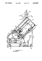
- FIG. 1 is an isometric view of the filter-washing system of the invention
- FIG. 2 is a front view thereof
- FIG. 3 is a cross-sectional view taken along line 3--3 of FIG. 2;
- FIG. 4 is a cross-sectional view taken along line 4--4 of FIG. 3;
- FIG. 5 is a cross-sectional view taken along line 5--5 of FIG. 3;
- FIG. 6 is a cross-sectional view taken along line 6--6 of FIG. 3;
- FIG. 7 is an isometric, detailed view of the three filter-supporting rotatable shafts with reciprocating nozzle heads thereabove of the apparatus of the invention, showing the nozzle heads and filters moving in a first direction;
- FIG. 8 is an isometric, detailed view of the three filter-supporting rotatable shafts with reciprocating nozzle heads thereabove of the apparatus of the invention, showing the nozzle heads and filters moving in a second, opposite direction;
- FIG. 9 is a side elevational view, in cross section, similar to FIG. 3, but showing the rotatable shafts of the apparatus holding a second type of cylindrical filter having an enlarged, intermediate flange member, whereby the outer half of each shaft of the apparatus of the invention is removed and placed in holders in order to accommodate this second type of cylindrical filter.
- the apparatus 10 has a main housing 12 which, in the preferred embodiment, is tilted or mounted at a 45 degree angle with respect to the horizontal, as clearly seen in FIGS. 1 and 3. This tilting of the main housing 12 ensures that the washing water used to wash the filters will exit from one specific location, as described below, so that the effluent may first be first filtered of solid waste material before the disposal thereof down a floor drain, and allows easy loading and unloading.
- the main housing 12 has a front wall 14, rear wall 16 top wall 18, bottom wall 20, and side walls 22, 24. Each wall is tilted and forms an acute angle with respect to a horizontal, as described above.
- the top wall 18 has a pivotal cover door 18' (see FIG. 9) by which access into the interior of the main housing is achieved in order to insert dirty filters needing to be washed, and to remove them after washing.
- the intersection of the front wall 14 and the bottom wall 20 is formed with an opening and an exit outlet or trough 26 through which the effluent flows, which effluent includes a mixture of washing water and sold waste material removed from the cylindrical filters washed thereby.
- the spout 26 directs the effluent to a portable or removable container 30 positionable below the trough, whereby the sold waste material in the effluent may be filtered out before the effluent is drained through a drain formed in the floor therebelow, as described below in greater detail.
- the main housing 12 is tiltably mounted via a mounting frame 32 consisting of a front or forward section 34.
- the front section also has a pair of side panels or splash guard-walls 22', 24', each defining a sloping upper edge surface which supports the main housing in its tilted state.
- the mounting frame also has a rear section 42 having a rear wall 44 consisting of a first vertical wall section 44' and a second tilted or forwardly sloping wall section 44", as best seen in FIG. 3, with the tilted wall section 44" being substantially coplanar with the rear wall 16 of the main housing.
- the upper end of the wall section 44" terminates considerably above the upper end of the vertical rear wall 38 of the front section 34, whereby an upper, tilted supporting wall 46 is provided which supports thereon the bottom wall 20 of the main housing 12.
- the rear section 42 also has a pair of side of side members or meshes 22" which serve as motor guards.
- the frame 32 is provided with swivel casters 46 in the front and rear sections thereof by which the entire apparatus 10 is made portable.
- the main housing 14 essentially serves as wash tank for washing clean a plurality of cylindrically-shaped filters 50.
- the filters 50 are used in cloth-dyeing equipment for removing wastes and other contaminants from the dyeing process.
- the solution flows radially into the filter and then longitudinally axially through the cylindrical filter, which filter periodically requires washing for removing the solid waste adhered thereto.
- the main housing 12 therefore, has a plurality of rotatable filter-supporting shafts or mandrels 52, which in the preferred embodiment number three.
- Each shaft 52 supports one cylindrical filter for rotating the filter during the washing process.
- each shaft 52 is comprised of two like parts: A lower part 53 and an upper part 55, as seen in FIG. 9.
- the upper and lower parts are removable from each other for purposes described below.
- the lower part 53 has a lower projecting rod 53' by which the entire shaft and filter are rotated by the drive means of the invention described below, and has an enlarged upper flange end 53" by which an outer, main elongated portion 52', that extends through the central, axial opening of a filter 50, is supported.
- An axial opening 57 is provided at the upper end portion of the central core of the lower section for receiving a lower projecting rod 59 of the upper section by which the upper section is removably secured to the lower section.
- the lower section or part 53 also has a spider member 54 positioned at its lower end portion, which spider member defines a plurality of angularly-spaced apart, sloping holding arms 56, with each arm 56 having a lower, outer flat section 56' about which the lower end of the cylindrical filter 50 is loosely retained thereon.
- the upper section 55 is virtually identical to the lower section except that the upper section does not have a spider arm 54 nor an axial opening 57.
- Each filter 50 is telescopingly mounted about the outer main elongated portions of the two sections 53, 55 of a shaft by the annular spider member 54, as best seen in FIGS. 3 and 5, and by a pair of rollers 60 mounted to the interior surface of the front wall 14.
- each pair of rollers 60 supporting an upper portion of one cylindrical filter 50 for rotation, as clearly shown in FIG. 3.
- Mounting brackets 62 rotatably mount the rollers 60 to the interior surface of the front wall, with the brackets, and therefore the rollers, being spaced apart in the widthwise direction in order to juxtaposition each adjacent pair of rollers under a respective rotatable shaft 52 for rotatably supporting one cylindrical filter for rotation.
- Each spider member 54 also has three spokes 63 spaced 120 degrees apart, with one of the three spokes terminating in a horizontal, right-angle piece 63'.
- a cylindrical filter 50 abuts against these spokes 63, with the horizontal piece 63' working with the flat, horizontal sections 56' of the spider member to receive therebetween the lower, outer circumferential surface of a cylindrical filter 50, for retaining the filter thereby during rotation.
- the filter is caused to rotate by the engagement of the horizontal, right-angle piece 63' with one of the three conventional protruding latches 51" (FIG. 7) provided on the outer circumference of the filter at its lower end.
- These latches are conventionally used for removably, axially-interconnecting two or more cylindrical filters in the dyeing apparatus.
- the right-angle piece 63' will rotate almost a full turn before engaging the latch 51" on the opposite side.
- the upper section 55 may be removed in order to accommodate a cylindrical filter 50 having an interior, central partition 50', which partition rests upon the upper edge-face of the lower section 53.
- nozzles 70 Mounted above the rotatable mandrels 52 are a similar number of nozzles 70 for directing a high-pressure stream of water to the cylindrical filters for washing them free of solid and other waste material, for subsequent reuse in the cloth-dyeing equipment.
- the three nozzles 70 are interconnected as one unit and reciprocably translate back and forth above the mandrels and the filters supported thereby.
- the nozzles 70 are interconnected by a connecting arm 72 best seen in FIG. 5, which connecting arm 72 has a central threaded opening that receives therethrough a lead screw 74.
- the lead screw 74 is mounted for rotation between the top wall 18 and bottom wall 20.
- Rotation of the lead screw in a first direction causes the simultaneous translation of the three nozzles 70 in one direction, while rotation of the lead screw in a second, opposite direction causes translation of the three nozzles in the opposite direction.
- the mandrel is also rotated to rotate the filter to expose the full 360 degree circumference of the filter to the high-pressures water stream.
- the rotation of the mandrels occurs in the same direction as the lead screw, so that when the lead screw's rotation is changed to translate the nozzles in the opposite direction, the direction of rotation of each mandrel is also changed, whereby solid particles not removed during the first translation of the nozzles would have a better chance of removal by exposure to the high-pressure water-stream by rotation of the mandrel in the opposite direction.
- Reversal of rotation of the lead screw is achieved by conventional contact limit switches stationed at the ends of the lead screw, which limit switches, upon being actuated by one of the nozzles 70, will cause a reversible d.c. gear-motor 76 to reverse direction.
- Each nozzle 70 is supplied water via a hose 78, a common supply line or manifold 79 feeding water to the three hoses 78, and a water pump 80 and associated three-phase, a.c. motor 82.
- Each nozzle is a conventional, rotary, nozzle head, which may be purchased from the Bill Voorhees Company, Milwaukee, Tenn.
- Each nozzle head provides a water-spray at 2000 psi at a temperature of 140 degrees F., with a flow rate of 2.9 gpm, and, while translating along a respective rotating cylindrical filter, also rotates in order to increase its effectiveness.
- the pump 80, motor 82, and common supply line or manifold 79 are mounted in the rear section 42 of the mounting frame 32, as clearly shown in FIGS. 3 and 9.
- a conventional water-pressure switch 79 such as a Bachman pressure switch part number S-225, detects the water pressure, and if there is no water feed, for whatever reason, power to the AC motor 82 and DC motor
- the reversible d.c. motor 76 not only drives the lead screw 74, but also rotates each of the rotatable mandrels 52, via the projecting rod 53' thereof, by means of a sprocket-and-chain arrangement 90 best seen in FIG. 6.
- the d.c., right-angle gear motor 76 drives a main drive-sprocket 92 which drives a chain 94, which, in turn, rotates driven sprockets 100, 102 and 104 operatively coupled to the three mandrels 52.
- Fourth driven sprocket 106 is operatively coupled to the lead screw 74.
- the sprockets 100, 102 and 104 are preferably 3/8 pitch, 26 tooth wheels, while the sprocket 106 is 3/8 pitch, 10 tooth wheel.
- the sprockets are chosen so that each mandrel Will have rotated one complete rotation before the washing water spray from a respective nozzle 70 will have translated a distance greater than the linear, horizontal range of the nozzle spray, so as to ensure that the entire circumferential surface of each cylindrical filter has been exposed to the spray during each translation of the nozzle.
- the d.c. motor 76 is mounted to the lower or bottom wall 20 of the main housing 12 by a bracket or ear 76', as best seen in FIG. 3, with the associated sprockets being mounted to and projecting below the bottom wall 20, with each respective projecting shaft 53' and lead screw 74 being coupled to one sprocket via a conventional coupler 110.
- a portable cart or wagon 30 which cart holds a cloth filter through which passes the effluent exiting from the outlet 26.
- the cloth filter is a conventional type of filter, and it filters out solid wastes, such as lint, from the effluent.
- the lint wagon 30 is best seen in FIGS. 1 and 9, and is made of a main body portion 30' of steel-wire mesh material, or the like, which allows the effluent to flow therethrough and directly into a drain hole (not shown) in the floor therebelow.
- the side walls 31, however, are steel plates that slope downwardly and inwardly toward each other, so that the effluent impinging thereon will be directed toward the bottom wall made of mesh material.
- Each side plate 31 mounts a pair of pedestals or braces 31', with each pedestal mounting a caster 33, whereby a total of four casters are provided by which the cart 30 may be rolled from the apparatus 10 to a dump site where the solid wastes are disposed of.
- a handle 35 allows one to grip the cart.
- the two rear casters, which are closest to the rear mesh panel that mounts the handle 35, are swivel casters, while the two front casters are rigid casters.
- the cloth filter (not shown) is draped inside the interior of the cart.
- a computerized control unit 120 may be provided that automatically controls the various operating parts, so that one or two complete cycles of operation may be performed.
- each shaft 52 having three spokes 63
Abstract
Description
Claims (19)
Priority Applications (1)
| Application Number | Priority Date | Filing Date | Title |
|---|---|---|---|
| US07/676,101 US5135580A (en) | 1991-03-27 | 1991-03-27 | Filter-washing system |
Applications Claiming Priority (1)
| Application Number | Priority Date | Filing Date | Title |
|---|---|---|---|
| US07/676,101 US5135580A (en) | 1991-03-27 | 1991-03-27 | Filter-washing system |
Publications (1)
| Publication Number | Publication Date |
|---|---|
| US5135580A true US5135580A (en) | 1992-08-04 |
Family
ID=24713231
Family Applications (1)
| Application Number | Title | Priority Date | Filing Date |
|---|---|---|---|
| US07/676,101 Expired - Fee Related US5135580A (en) | 1991-03-27 | 1991-03-27 | Filter-washing system |
Country Status (1)
| Country | Link |
|---|---|
| US (1) | US5135580A (en) |
Cited By (26)
| Publication number | Priority date | Publication date | Assignee | Title |
|---|---|---|---|---|
| US5336332A (en) * | 1991-06-26 | 1994-08-09 | Kabushiki Kaisha Powrex | Washing apparatus and method for fluidized bed pelletizing and drying machine |
| WO2000032325A1 (en) * | 1998-11-30 | 2000-06-08 | Lonnie Joe Milligan | Filter cleaning device |
| US6443169B1 (en) * | 2000-06-10 | 2002-09-03 | Fernando M Ferreira | Portable apparatus for rotatably maintaining a pumping conduit on an incline |
| US6575180B2 (en) * | 2001-05-16 | 2003-06-10 | Jeffery A. Jelten | Spa filter cleaning and rinsing device |
| DE19920892B4 (en) * | 1998-05-07 | 2004-05-13 | Takeshi Yoshida | Device and method for removing sludge from a filter for use in an electrical discharge machine |
| US20080006290A1 (en) * | 2006-07-10 | 2008-01-10 | Kuniaki Yamanaka | Fluidized bed apparatus and filter washing method for fluidized bed apparatus |
| US7393387B1 (en) * | 2005-06-20 | 2008-07-01 | Andreas Heisey | Particle filter cleaning apparatus |
| JP2008279429A (en) * | 2007-04-13 | 2008-11-20 | Freunt Ind Co Ltd | Filter cleaning apparatus and filter cleaning method |
| US20090083931A1 (en) * | 2007-10-02 | 2009-04-02 | Troy Douglas Harris | Spray cleaning apparatus for caul screens |
| CN101244351B (en) * | 2008-02-26 | 2010-06-09 | 叶建荣 | Water purifying structure for water purifier |
| US20100307339A1 (en) * | 2009-06-08 | 2010-12-09 | Tadrous Ted N | Apparatus and method for regenerating a carbon filter |
| WO2012031283A1 (en) * | 2010-09-03 | 2012-03-08 | Love Johnny L | Filtration method with self-cleaning filter assembly |
| DE102011105944A1 (en) * | 2011-06-29 | 2013-01-03 | Siegfried Keusch | Device for filtering wastewater that is obtained during cleaning using high pressure cleaners, by suctioning wastewater under reduced pressure using suction cup into water tank, and passing wastewater through filter basket, and purifying |
| US20130037061A1 (en) * | 2011-08-10 | 2013-02-14 | Gita Green, Llc | Apparatus and Method for Cleaning Air Filters |
| WO2013134400A1 (en) * | 2012-03-06 | 2013-09-12 | Filter Wizard, Llc | Apparatus and method for cleaning of swimming pool and spa cartridge filters |
| US20140209530A1 (en) * | 2013-01-29 | 2014-07-31 | Bilfinger Water Technologies, Inc. | Sieve box and adjustable nozzle assembly |
| US9415334B2 (en) * | 2011-05-27 | 2016-08-16 | Robert T. Rife | Air filter reconditioning apparatus and method |
| USD765322S1 (en) | 2011-08-10 | 2016-08-30 | Gita Green, Inc. | Apparatus for cleaning air filters |
| US9480941B2 (en) | 2007-10-29 | 2016-11-01 | Gita Green, Inc. | Apparatus and method for cleaning air filters |
| CN106391621A (en) * | 2016-11-07 | 2017-02-15 | 丁晓霞 | Test tube cleaning device and method |
| US9675910B1 (en) * | 2012-03-06 | 2017-06-13 | Robert Louis Wade | Apparatus and method for cleaning of swimming pool and spa cartridge filters |
| NL2018396A (en) * | 2016-02-19 | 2017-08-24 | Toussaint Perry | Cleaning device for cleaning a cylindrical filter |
| RU2630794C1 (en) * | 2016-07-12 | 2017-09-13 | Общество с ограниченной ответственностью "Газпром добыча Ямбург" | Filter cartridges cleaning and washing system |
| CN108393296A (en) * | 2018-03-07 | 2018-08-14 | 福建省鑫福智能机电科技有限公司 | Tea processing high-efficiency washing device |
| US11052340B1 (en) * | 2020-11-06 | 2021-07-06 | Bradley W. Boesel | Cylindrical filter cartridge cleaning device |
| US20220193590A1 (en) * | 2020-12-22 | 2022-06-23 | Spraying Systems Co. | Apparatus and method for cleaning filter cartridges |
Citations (18)
| Publication number | Priority date | Publication date | Assignee | Title |
|---|---|---|---|---|
| US3120346A (en) * | 1962-10-31 | 1964-02-04 | American Mach & Foundry | Rotary spray devices |
| US3121536A (en) * | 1961-07-28 | 1964-02-18 | Lloyd E Mckibben | Tank cleaning apparatus |
| US3442273A (en) * | 1967-08-31 | 1969-05-06 | Harry W Hanish | Filter washing apparatus |
| US3472251A (en) * | 1966-10-10 | 1969-10-14 | Parker Bruce H Jun | Centrifugal water-action roller cleaner |
| US3526237A (en) * | 1968-05-08 | 1970-09-01 | Scott E Neill Jr | Filter cleaner |
| US3604437A (en) * | 1969-05-26 | 1971-09-14 | Tamonite Inc | Portable air filter cleaner |
| US3606897A (en) * | 1970-01-26 | 1971-09-21 | Benjamin F Tobin | Apparatus for cleaning of canister type air filters |
| US3873364A (en) * | 1973-06-07 | 1975-03-25 | Joseph L Smith | Paint roller sleeve washer |
| US3998656A (en) * | 1976-01-07 | 1976-12-21 | Grotto La Von P | Method and apparatus for cleaning cylindrical air filters |
| US4178652A (en) * | 1978-04-24 | 1979-12-18 | Arvey Corporation | Apparatus for cleaning roller surfaces |
| US4299245A (en) * | 1980-04-21 | 1981-11-10 | Clapper Millard F | Filter cleaning system |
| US4585019A (en) * | 1984-06-08 | 1986-04-29 | Jacobson Dwight W | Heavy duty air filter reconditioning system |
| US4708152A (en) * | 1986-08-26 | 1987-11-24 | Hibberd Carl G | Paint roller cleaner apparatus |
| US4808234A (en) * | 1984-08-30 | 1989-02-28 | Mcwinn Filter Services Ltd. | Cleaner assembly for air filters |
| US4815523A (en) * | 1985-04-26 | 1989-03-28 | Kraftanlagen Ag | Device and process for cleaning a recirculation-type regenerative heat exchanger |
| US4828179A (en) * | 1988-06-03 | 1989-05-09 | Garner Jim W | Rotating spray apparatus |
| US4913346A (en) * | 1987-12-25 | 1990-04-03 | Tosoh Corporation | Rotary washing nozzle |
| US4967776A (en) * | 1989-12-12 | 1990-11-06 | Gordon Folmar | Oil filter cleaning system |
-
1991
- 1991-03-27 US US07/676,101 patent/US5135580A/en not_active Expired - Fee Related
Patent Citations (18)
| Publication number | Priority date | Publication date | Assignee | Title |
|---|---|---|---|---|
| US3121536A (en) * | 1961-07-28 | 1964-02-18 | Lloyd E Mckibben | Tank cleaning apparatus |
| US3120346A (en) * | 1962-10-31 | 1964-02-04 | American Mach & Foundry | Rotary spray devices |
| US3472251A (en) * | 1966-10-10 | 1969-10-14 | Parker Bruce H Jun | Centrifugal water-action roller cleaner |
| US3442273A (en) * | 1967-08-31 | 1969-05-06 | Harry W Hanish | Filter washing apparatus |
| US3526237A (en) * | 1968-05-08 | 1970-09-01 | Scott E Neill Jr | Filter cleaner |
| US3604437A (en) * | 1969-05-26 | 1971-09-14 | Tamonite Inc | Portable air filter cleaner |
| US3606897A (en) * | 1970-01-26 | 1971-09-21 | Benjamin F Tobin | Apparatus for cleaning of canister type air filters |
| US3873364A (en) * | 1973-06-07 | 1975-03-25 | Joseph L Smith | Paint roller sleeve washer |
| US3998656A (en) * | 1976-01-07 | 1976-12-21 | Grotto La Von P | Method and apparatus for cleaning cylindrical air filters |
| US4178652A (en) * | 1978-04-24 | 1979-12-18 | Arvey Corporation | Apparatus for cleaning roller surfaces |
| US4299245A (en) * | 1980-04-21 | 1981-11-10 | Clapper Millard F | Filter cleaning system |
| US4585019A (en) * | 1984-06-08 | 1986-04-29 | Jacobson Dwight W | Heavy duty air filter reconditioning system |
| US4808234A (en) * | 1984-08-30 | 1989-02-28 | Mcwinn Filter Services Ltd. | Cleaner assembly for air filters |
| US4815523A (en) * | 1985-04-26 | 1989-03-28 | Kraftanlagen Ag | Device and process for cleaning a recirculation-type regenerative heat exchanger |
| US4708152A (en) * | 1986-08-26 | 1987-11-24 | Hibberd Carl G | Paint roller cleaner apparatus |
| US4913346A (en) * | 1987-12-25 | 1990-04-03 | Tosoh Corporation | Rotary washing nozzle |
| US4828179A (en) * | 1988-06-03 | 1989-05-09 | Garner Jim W | Rotating spray apparatus |
| US4967776A (en) * | 1989-12-12 | 1990-11-06 | Gordon Folmar | Oil filter cleaning system |
Cited By (39)
| Publication number | Priority date | Publication date | Assignee | Title |
|---|---|---|---|---|
| US5336332A (en) * | 1991-06-26 | 1994-08-09 | Kabushiki Kaisha Powrex | Washing apparatus and method for fluidized bed pelletizing and drying machine |
| DE19920892B4 (en) * | 1998-05-07 | 2004-05-13 | Takeshi Yoshida | Device and method for removing sludge from a filter for use in an electrical discharge machine |
| WO2000032325A1 (en) * | 1998-11-30 | 2000-06-08 | Lonnie Joe Milligan | Filter cleaning device |
| US6443169B1 (en) * | 2000-06-10 | 2002-09-03 | Fernando M Ferreira | Portable apparatus for rotatably maintaining a pumping conduit on an incline |
| US6575180B2 (en) * | 2001-05-16 | 2003-06-10 | Jeffery A. Jelten | Spa filter cleaning and rinsing device |
| US7393387B1 (en) * | 2005-06-20 | 2008-07-01 | Andreas Heisey | Particle filter cleaning apparatus |
| US20080006290A1 (en) * | 2006-07-10 | 2008-01-10 | Kuniaki Yamanaka | Fluidized bed apparatus and filter washing method for fluidized bed apparatus |
| JP2008279429A (en) * | 2007-04-13 | 2008-11-20 | Freunt Ind Co Ltd | Filter cleaning apparatus and filter cleaning method |
| US20090083931A1 (en) * | 2007-10-02 | 2009-04-02 | Troy Douglas Harris | Spray cleaning apparatus for caul screens |
| US7874302B2 (en) * | 2007-10-02 | 2011-01-25 | Troy Douglas Harris | Spray cleaning apparatus for caul screens |
| US9480941B2 (en) | 2007-10-29 | 2016-11-01 | Gita Green, Inc. | Apparatus and method for cleaning air filters |
| CN101244351B (en) * | 2008-02-26 | 2010-06-09 | 叶建荣 | Water purifying structure for water purifier |
| US20100307339A1 (en) * | 2009-06-08 | 2010-12-09 | Tadrous Ted N | Apparatus and method for regenerating a carbon filter |
| US8241403B2 (en) * | 2009-06-08 | 2012-08-14 | Catalytic Solutions, Inc. | Apparatus and method for regenerating a carbon filter |
| WO2012031283A1 (en) * | 2010-09-03 | 2012-03-08 | Love Johnny L | Filtration method with self-cleaning filter assembly |
| US8647516B2 (en) | 2010-09-03 | 2014-02-11 | Johnny Leon LOVE | Filtration method with self-cleaning filter assembly |
| US9415334B2 (en) * | 2011-05-27 | 2016-08-16 | Robert T. Rife | Air filter reconditioning apparatus and method |
| DE102011105944A1 (en) * | 2011-06-29 | 2013-01-03 | Siegfried Keusch | Device for filtering wastewater that is obtained during cleaning using high pressure cleaners, by suctioning wastewater under reduced pressure using suction cup into water tank, and passing wastewater through filter basket, and purifying |
| DE102011105944B4 (en) * | 2011-06-29 | 2015-04-23 | Siegfried Keusch | Device for the filtration of dirty water |
| US8668782B2 (en) * | 2011-08-10 | 2014-03-11 | Gita Green, Llc | Apparatus and method for cleaning air filters |
| US9718015B2 (en) | 2011-08-10 | 2017-08-01 | Gita Green, Inc. | Apparatus and method for cleaning air filters |
| US20130037061A1 (en) * | 2011-08-10 | 2013-02-14 | Gita Green, Llc | Apparatus and Method for Cleaning Air Filters |
| USD765322S1 (en) | 2011-08-10 | 2016-08-30 | Gita Green, Inc. | Apparatus for cleaning air filters |
| WO2013134400A1 (en) * | 2012-03-06 | 2013-09-12 | Filter Wizard, Llc | Apparatus and method for cleaning of swimming pool and spa cartridge filters |
| US9675910B1 (en) * | 2012-03-06 | 2017-06-13 | Robert Louis Wade | Apparatus and method for cleaning of swimming pool and spa cartridge filters |
| CN104955539A (en) * | 2013-01-29 | 2015-09-30 | 贝尔芬格水处理技术股份有限公司 | Sieve box and adjustable nozzle assembly |
| US20140209530A1 (en) * | 2013-01-29 | 2014-07-31 | Bilfinger Water Technologies, Inc. | Sieve box and adjustable nozzle assembly |
| US9908147B2 (en) * | 2013-01-29 | 2018-03-06 | Aqseptence Group, Inc. | Sieve box and adjustable nozzle assembly |
| WO2014120712A1 (en) * | 2013-01-29 | 2014-08-07 | Bilfinger Water Technologies, Inc. | Sieve box and adjustable nozzle assembly |
| NL2018396A (en) * | 2016-02-19 | 2017-08-24 | Toussaint Perry | Cleaning device for cleaning a cylindrical filter |
| WO2017142413A1 (en) * | 2016-02-19 | 2017-08-24 | Perry Toussaint | Cleaning device for cleaning a cylindrical filter |
| RU2630794C1 (en) * | 2016-07-12 | 2017-09-13 | Общество с ограниченной ответственностью "Газпром добыча Ямбург" | Filter cartridges cleaning and washing system |
| CN106391621A (en) * | 2016-11-07 | 2017-02-15 | 丁晓霞 | Test tube cleaning device and method |
| CN106391621B (en) * | 2016-11-07 | 2018-09-25 | 安徽泓森高科林业股份有限公司 | A kind of test tube cleaning device and its cleaning method |
| CN108393296A (en) * | 2018-03-07 | 2018-08-14 | 福建省鑫福智能机电科技有限公司 | Tea processing high-efficiency washing device |
| US11052340B1 (en) * | 2020-11-06 | 2021-07-06 | Bradley W. Boesel | Cylindrical filter cartridge cleaning device |
| US11052341B1 (en) * | 2020-11-06 | 2021-07-06 | Bradley W. Boesel | Cylindrical filter cartridge device |
| US20220193590A1 (en) * | 2020-12-22 | 2022-06-23 | Spraying Systems Co. | Apparatus and method for cleaning filter cartridges |
| US11845028B2 (en) * | 2020-12-22 | 2023-12-19 | Spraying Systems Co. | Apparatus and method for cleaning filter cartridges |
Similar Documents
| Publication | Publication Date | Title |
|---|---|---|
| US5135580A (en) | Filter-washing system | |
| US6336239B1 (en) | Bin washer | |
| CN215958215U (en) | Red date sprays belt cleaning device | |
| CN111558608A (en) | Environment-friendly solid waste high-efficiency treatment equipment | |
| CN114405161B (en) | Method for quickly replacing filter element of water vending machine | |
| US4620478A (en) | Filtration apparatus for use with a meat-piece fluid injector | |
| JPH0938610A (en) | Cleaning method and cleaning device for pond | |
| US5038809A (en) | High pressure solventless mask washer | |
| RU2348553C1 (en) | Washing machine for automated cleaning of mechanical parts and components | |
| CN109759364A (en) | A kind of quick-frozen aquatic products raw material cleaning device | |
| CN211812023U (en) | Belt conveyor cleaning device for coal mine machine electricity | |
| CN211159141U (en) | Dust device is used in processing of living beings pellet fuel | |
| JP2878013B2 (en) | Tank cleaning method | |
| CN114643536B (en) | Pipeline grinding equipment with cutting fluid recycling function | |
| US3552405A (en) | Apparatus for cleaning or treating articles | |
| CN210409767U (en) | Special rotary drum microstrainer of slaughter sewage treatment | |
| CN211027257U (en) | Bolt belt cleaning device | |
| CN212668400U (en) | Multipurpose belt cleaning device | |
| CN215276403U (en) | Dust device is used in construction of highway safety life protection engineering | |
| CN218874746U (en) | Cooling device for guide arm drilling | |
| CN110616918A (en) | Swimming pool washs dolly | |
| JPH11151470A (en) | Method for washing paint containers or the like and device therefor | |
| CN215696275U (en) | Engineering waste treatment device | |
| CN216320821U (en) | Dust falling device for oil powder removal processing | |
| CN116078710B (en) | Antibiotic mould proof belt cleaning device for mahogany furniture |
Legal Events
| Date | Code | Title | Description |
|---|---|---|---|
| AS | Assignment |
Owner name: UNION UNDERWEAR COMPANY, INC., A CORP. OF NEW YORK Free format text: ASSIGNMENT OF ASSIGNORS INTEREST.;ASSIGNORS:CANTRELL, HENRY L.;WETHINGTON, GLENN M.;REEL/FRAME:005655/0963 Effective date: 19910325 |
|
| AS | Assignment |
Owner name: BANKERS TRUST COMPANY, A NY CORP., STATELESS Free format text: SECOND AMENDED AND RESTATED SECURITY INTEREST.;ASSIGNOR:UNION UNDERWEAR COMPANY, INC., A NY CORP.;REEL/FRAME:006253/0116 Effective date: 19920820 |
|
| FPAY | Fee payment |
Year of fee payment: 4 |
|
| AS | Assignment |
Owner name: BANK OF AMERICA, N.A., NORTH CAROLINA Free format text: SECURITY INTEREST;ASSIGNOR:UNION UNDERWEAR COMPANY, A NEW YORK CORPORATION;REEL/FRAME:010113/0396 Effective date: 19990310 |
|
| REMI | Maintenance fee reminder mailed | ||
| LAPS | Lapse for failure to pay maintenance fees | ||
| FP | Lapsed due to failure to pay maintenance fee |
Effective date: 20000804 |
|
| AS | Assignment |
Owner name: FRUIT OF THE LOOM, INC., KENTUCKY Free format text: ASSIGNMENT OF ASSIGNORS INTEREST;ASSIGNOR:UNION UNDERWEAR COMPANY, INC.;REEL/FRAME:012884/0918 Effective date: 20020426 |
|
| AS | Assignment |
Owner name: UNION UNDERWEAR COMPANY, LLC, KENTUCKY Free format text: CORRECTED RECORDATION COVER SHEET TO CORRECT NAME OF ASSIGNEE PREVIOUSLY RECORDED ON REEL 012884 FRAME 0918.;ASSIGNOR:UNION UNDERWEAR COMPANY, INC.;REEL/FRAME:013169/0171 Effective date: 20020426 |
|
| STCH | Information on status: patent discontinuation |
Free format text: PATENT EXPIRED DUE TO NONPAYMENT OF MAINTENANCE FEES UNDER 37 CFR 1.362 |