US5092164A - Thermal air-flow sensor - Google Patents
Thermal air-flow sensor Download PDFInfo
- Publication number
- US5092164A US5092164A US07/656,607 US65660791A US5092164A US 5092164 A US5092164 A US 5092164A US 65660791 A US65660791 A US 65660791A US 5092164 A US5092164 A US 5092164A
- Authority
- US
- United States
- Prior art keywords
- amount
- intake air
- measured
- calculating
- full cycle
- Prior art date
- Legal status (The legal status is an assumption and is not a legal conclusion. Google has not performed a legal analysis and makes no representation as to the accuracy of the status listed.)
- Expired - Fee Related
Links
Images

Classifications
-
- G—PHYSICS
- G01—MEASURING; TESTING
- G01F—MEASURING VOLUME, VOLUME FLOW, MASS FLOW OR LIQUID LEVEL; METERING BY VOLUME
- G01F1/00—Measuring the volume flow or mass flow of fluid or fluent solid material wherein the fluid passes through a meter in a continuous flow
- G01F1/72—Devices for measuring pulsing fluid flows
-
- F—MECHANICAL ENGINEERING; LIGHTING; HEATING; WEAPONS; BLASTING
- F02—COMBUSTION ENGINES; HOT-GAS OR COMBUSTION-PRODUCT ENGINE PLANTS
- F02D—CONTROLLING COMBUSTION ENGINES
- F02D41/00—Electrical control of supply of combustible mixture or its constituents
- F02D41/02—Circuit arrangements for generating control signals
- F02D41/18—Circuit arrangements for generating control signals by measuring intake air flow
- F02D41/187—Circuit arrangements for generating control signals by measuring intake air flow using a hot wire flow sensor
-
- G—PHYSICS
- G01—MEASURING; TESTING
- G01F—MEASURING VOLUME, VOLUME FLOW, MASS FLOW OR LIQUID LEVEL; METERING BY VOLUME
- G01F1/00—Measuring the volume flow or mass flow of fluid or fluent solid material wherein the fluid passes through a meter in a continuous flow
- G01F1/68—Measuring the volume flow or mass flow of fluid or fluent solid material wherein the fluid passes through a meter in a continuous flow by using thermal effects
- G01F1/696—Circuits therefor, e.g. constant-current flow meters
- G01F1/698—Feedback or rebalancing circuits, e.g. self heated constant temperature flowmeters
- G01F1/6986—Feedback or rebalancing circuits, e.g. self heated constant temperature flowmeters with pulsed heating, e.g. dynamic methods
Definitions
- the present invention relates to a sensor for detecting an amount of intake air used for a control apparatus for an internal combustion engine.
- thermal type airflow meter which includes a heat generating body arranged in an intake line of an internal combustion engine. A time for obtaining an increase of the temperature of a predetermined value of the body is measured, and an amount of the intake air is obtained from the measured time. The greater the increase of the speed of the intake air corresponding to the amount of the intake air, the longer the time needed for obtaining an increase of the temperature to the predetermined value. The measurement of this time makes it possible to determine the amount of intake air flowing into the internal combustion engine. (See Japanese patent Publication No. 55-50121)
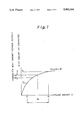
- FIG. 1 shows a relationship between an intake air amount G and a conducted heat h, which is expressed by the following equation,
- the output value of the airflow meter is determined by a thermally conducted heat amount for a predetermined period prior to at moment, which results in a non-linear relationship between the G and the h. It is assumed that the flow amount is varied between the values of Gd and Gu, which causes the output to be moved between hd and hu, the mean value of which is hp'.
- the Japanese Unexamined Utility Model Publication No. 61-14924 discloses a concept of calculating a ratio of an average value of the output from the air flow meter in a half period of one full cycle of a variation of the output level of the airflow meter, to thus provide a larger value, and an average value of the output in a remaining half period, to thus provide a smaller value.
- This ratio corresponds to a degree of pulsation in the output signal from the airflow meter.
- this value is used for the correction of a mean output value from the airflow meter, whereby a correct value of the intake air can be obtained which is not influenced by the effect of the pulsation.
- This prior art calculates an integrated value of adjacent halves in one complete cycle of a variation of a sensor signal, a ratio of which integrated values is used to calculate a variation ratio, which is multiplied by an average value of the detected signal in one full cycle to obtain a corrected, precise value of the amount of the air introduced into the engine.
- This suffers from a drawback that, since a mean value in one full cycle is calculated to obtain the variation ratio, an acceleration or deceleration of the engine causes the value of the variation ratio to be displaced from the desired value. Also, such an acceleration or deceleration causes the mean value itself to be varied in one full cycle, which causes the integrated values found during consecutive half cycles to be changed independent by of the the effect of the pulsation.
- the variation ratio as a ratio of the integrated values in the consecutive half cycles in the sensor signal is different from the desired value, and accordingly, a correct compensation of the effect of the intake air amount pulsation on the intake air sensor signal can not be obtained, and thus a precise detection of the intake air amount can not be attained.
- An object of the present invention is to provide a airflow sensor capable of detecting a precise value of the intake air amount which is not influenced by an acceleration or deceleration of the engine.
- an apparatus for measuring an amount of air passed through an intake system for an internal combustion engine, which amount of air is pulsatively changed at a predetermined cycle, said apparatus comprising;
- (f) means for calculating at one full cycle a total amount of variation of the measured values at the sampling timings when the effect of the engine transient state on the total amount of the variation is eliminated, and;
- (g) means for obtaining an average intake air amount corrected in accordance with the total amount of compensated variation.
- FIG. 1 shows a relationship between the intake air amount and an amount of heat conducted to the air
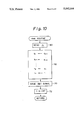
- FIG. 2 shows a schematic view of the air flow sensor according to the present invention, together with an engine control circuit
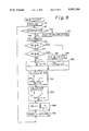
- FIGS. 3 to 6 are flowcharts illustrating how the measurement of the intake air amount by the air-flow meter according to the present invention is carried out
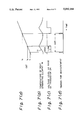
- FIGS. 7(a) to (d) are timing charts illustrating the measuring operation of the sensor according to the present invention.
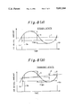
- FIG. 8 which includes parts (a) and (b), schematically illustrates pulsative changes in the measuring signal from the sensor according to the present invention
- FIGS. 9 and 10 are flowcharts of the second embodiment, which correspond to FIGS. 3 and 4, respectively, of the first embodiment.
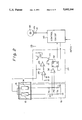
- the airflow sensor includes a bridge circuit 10, comprising a temperature detection resister 12, a heat generating resistor 14, and adjusting resistors R 1 , R 2 and R 3 .
- the temperature detection resistor 12 and the heat generating resistor 14 are arranged in an intake pipe 16 of an internal combustion engine.
- the temperature detection resistor 12, the heat generating resistor 14, and the adjusting resistors R 1 , R 2 and R 3 are interconnected so that a bridge circuit is constructed.
- the electric resistance value of the temperature detecting resistor 12 varies as the amount of air in the intake pipe introduced into the engine varies.
- a electric current control circuit 20 is provided for controlling the electric voltage applied to the heat generating resistor 14, so that the temperature of the heat generating resistor 14 is higher than that of the temperature detecting resistor 12 by a predetermined value.
- a means is provided for detecting a time at which the temperature of the heat generating resistor 14 is made higher than that of the temperature detecting resistor by the predetermined value, which time enables the intake air amount to the internal combustion engine to be determined.
- the electric current control circuit 20 includes transistors 22 and 24, operating amplifiers 26, 28 and 30, and a flip-flop circuit 32.
- the transistor 22 controls the electric current in the heating resistance 14, and the operating amplifier 28 attains a feedback-control of a constant voltage of the electric voltage in the bridge circuit 10.
- the operating amplifier 28 is provided with an inverted input connected between the heat generating resistor 14 and transistor 22, and a non-inverted input connected to the operating amplifier 26, which applies a reference voltage to the operating amplifier 28 so that a constant voltage is applied to the bridge circuit 10.
- the bridge circuit 10 is provided with bridge points P 1 and P 2 , which are respectively connected to inputs of the operating amplifier 30.
- the flip-flop circuit 32 is provided with a reset terminal R connected to the operating amplifier 30, a set terminal S connected to an engine control circuit 40, an inverted output connected to the base of the transistor 24, and a non-inverted output connected to the control circuit 40.
- the engine control circuit 40 is constructed as a micro-computer system for controlling the fuel injection amount and ignition timing. Such a fuel injection control and ignition timing control are not directly related to the present invention, and therefore, an explanation thereof is omitted.
- the control of the application of the electric voltage by the bridge circuit 10 in this embodiment is carried out at intervals of 4 milliseconds.
- a set signal is sent from the control circuit 40 to the set input S of the flip-flop circuit 32, which causes the inverted output of the flip-flop circuit 32 to become Low level.
- the low level at the inverted output of the flip-flop circuit 32 causes the transistor 24 to be made ON, whereby the voltage level at the base of the transistor 22 is made High.
- the high level at the base causes the transistor 22 to be made ON, which causes the heat generating resistor 14 to be energized.
- the voltage levels at the bridge points P 1 and P 2 are not balanced (P 1 >P 2 ) but when the temperature of the heat generating element 14 is higher than that of the temperature sensing element 12, by a predetermined value, a balanced condition of the voltage levels at the bridge points P 1 and P 2 is obtained, and thus the operating amplifier 30 outputs a High level signal to the reset terminal R of the flip-flop circuit 32, which then outputs a High level signal from the inverted output thereof, making the transistor 24 ON.
- the transistor 24 is made ON, the level at the base is made Low, and thus it is made OFF, whereby the supply of the electric current to the heat generating element 14 is stopped.
- the set terminal S and non-inverted output of the flip-flop circuit 32 are connected to the microcomputer 40, which is used for calculating the variation ratio and intake air amount from the time that the heat generating resistor 14 is energized.
- a crank angle sensor 41 such as a Hall element is provided adjacent to a rotating element connected to a crankshaft (not shown) of an internal combustion engine.
- the rotating element is, for example, a distributing shaft 43 of a distributor (not shown) of the internal combustion engine.
- a toothed element 45 is connected to the shaft 43, so that the crank angle sensor 41 issues pulse signals at a predetermined angle of rotation of the crankshaft (CA), such as at 30 degrees CA.
- CA crankshaft
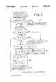
- FIG. 3 shows a main routine which is executed when an ignition key switch (not shown) of the internal combustion engine is made ON.
- Step 41 generally shows an initialize routine which is adapted for initializing, for example, a RAM and registers.
- the routine goes to step 43 to execute the interruption routines such as those shown in FIGS. 5 to 7.
- Steps 44 to 49 show a part of the main routine for calculating a average intake air amount GA.
- a number n of data of a corrected, measured intake air amount G in one measurement cycle which is a basis for the calculation of the mean intake air amount GA, is calculated by
- T180 is a time in milliseconds necessary for a rotation of the crankshaft (not shown) of a four cylinder internal combustion engine through an angle of 180 degrees, which corresponds to one cycle of pulsation in the intake air amount.
- a time necessary for rotating the crankshaft through an angle of 120 degrees is used, as it corresponds to one cycle of pulsation of the intake air for that engine.
- the measurement of the intake air amount is executed at intervals of 4 milliseconds, and thus the T180 divided by 4 corresponds to a number of data of the measured intake air amount for a period in which the crankshaft is rotated through 180 degrees.
- an average value of consecutive data of the measured intake air amount of number n is calculated by ##EQU1##
- This averaged measured intake air amount is used for compensating the pulsation of the values of the measured intake air amount occurring during the rotation of the crankshaft. As shown in FIGS. 8(a) and (b), a pulsative change occurs in the value of the intake air amount, one cycle of which corresponds to 180 degrees of rotation of the crankshaft when the engine has four cylinders.
- the average value GA of the intake air amount is an average for this cycle.
- Steps 45 and 46 are guard routines for limiting the values of n, in accordance with engine speed NE.
- step 45 it is determined if the engine speed NE is smaller than a predetermined value N 1 .
- the routine goes to step 46 and a predetermined value n A is moved to n.
- T180 which is a time needed for a 180 degrees rotation of the crankshaft, is relatively longer, a large value number n is obtained, and thus a predetermined fixed value n A , even if smaller than the value calculated at step 44, is sufficient to obtain a desired precision of the average intake air amount.
- step 47 it is determined if the engine speed is higher than a predetermined value N 2 .
- the routine goes to step 48 and a predetermined value nB is moved to n.
- a predetermined value nB is selected so that a desired average value of the measured intake air amount is obtained, whereby the effect of the pulsation of the intake air amount is cancelled.
- a variation ratio PL i calculated by ##EQU2## where the first term in the numerator ##EQU3## corresponds to a total variation in the intake air amount ⁇ in one full cycle of 180 degrees CA (one sampling period) in FIG. 8(a) or (b).
- the second term in the numerator ##EQU4## corresponds to a variation ⁇ ' in an average value in the intake amount in one sampling period (180 degrees CA). When the engine is in a steady state, the second term would be zero as shown in FIG.
- the second term corresponds to a change in the average value in one cycle, which is equal to the absolute value of G 1 -G n , and by subtracting the second term from the first term, a variation caused only by the intake pressure pulsation itself can be taken out, as fully described later, and used for correcting the measured value to detect precise amount of intake air.
- the first term and the second term are divided by the average value for obtaining the variation ratio, which corresponds to a ratio of the total variation to the average value in one variation cycle of 180 degrees CA.
- a factor FPL is calculated and is used for converting the variation ratio PL to a correction factor FPL.
- a desired relationship between the variation ratio PL and the correction factor is such that, when the variation ratio is smaller than a predetermined value PL 1 , the correction factor is maintained at 1.0, and accordingly, a correction of the measured intake air amount is not carried out, and such that, when the variation ratio is higher than a predetermined value PL 1 , the correction factor is increased in accordance with the increase in the value of the PL.
- a corrected average intake air amount GAADJ is calculated by
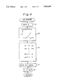
- FIG. 4 shows a routine which is executed at intervals of 4 milliseconds.
- a value of data of an energizing period h is read out. This is an ON time of the heat generating element 14 obtained when this routine is carried out at the preceding timing, i.e., 4 milliseconds before.
- a measured intake air amount G at this moment is calculated from the h.
- a predetermined relationship which exists between the intake air amount G and the ON time h is stored as a map in a memory of the microcomputer 40, and a map interpolation calculation is carried out to obtain a value of the intake air amount G corresponding to the read out energizing time h.
- step 64 consecutive measured values of intake air amounts G 1 , G 2 , . . . , and G n of number of n are updated, i.e., the newest measured value G at step 62 is moved into G 1 and the previous value of G 1 is moved into G 2 . Similarly, the previous value G n-1 is moved into G n .
- step 70 a set signal is output to the set terminal of the flip-flop circuit 32 from the control circuit 40 whereby the heat generating element 14 is energized for 4 milliseconds. Then, at step 7, a value of a counter CNT is moved into T 1 ; this indicates the time at which the energization of the heater element 14 of this period is commenced.
- FIG. 5 shows a routine which is commenced when a condition of the non-inverted output from the flip-flop circuit 32 is changed from High to Low, i.e., the heat generating element 14 is made OFF because the temperature of the heat generating element 14 is higher than that of the heat measuring element 12, by a predetermined value.
- the value of the counter CNT is moved into t e , which indicates the time at which the energization of the heater element 14 of this period is stopped.
- the ON time h of this cycle is calculated as t e subtracted by t 1 .
- t e -t l is a time at which the heat generating element 14 is energized at this cycle of 4 milliseconds, and is used for calculating the intake air amount G at step 62 during the execution of the following 4 milliseconds routine in FIG. 4.
- FIG. 6 shows a crank angle interruption routine carried out at the output of each 30 degrees pulse signal from the crank angle sensor 41.
- step 80 it is determined if the crankshaft has rotated through 180 degrees CA, which corresponds to one complete cycle of pulsative change in the intake air in the four cylinder engine in this embodiment.
- the routine goes to step 82 and the value of the counter CNT is moved to t 1 .
- step 86 the time T180 needed for a rotation through 180 degrees by the crankshaft, and corresponding to one complete cycle of pulsative change in the intake air amount, is calculated as t 1 subtracted by t 2 , and at step 88, the value of t 1 obtained at step 82 is moved to t 2 .
- other routines to be executed at each 30 degrees CA signal are carried out, such as a fuel injection control and ignition timing control, as is well known.
- FIG. 7(a) to (d) illustrate how the timing control in the first embodiment is carried out.
- the value of the counter CNT is continuously increased, as when in FIG. 7(a), and at a time t 1 , a set signal is output to the flip-flop circuit 32 at step 70 in FIG. 4, whereby the voltage at the base of the transistor 24 is made low level, causing the transistor 24 to be made OFF, and the transistor 22 to be made ON, and thus the heating of the heat generating element 14 is commenced.
- the temperature of the element 14 is increased as shown by a line D1 in FIG. 7(b).
- the voltage levels at the bridge points P 1 and P 2 are balanced, and therefore, the flip-flop circuit 32 is reset, the voltage level at the base of the transistor 24 is made high, as shown by FIG. 7(c), causing the transistor 24 to be made ON and the transistor 22 to be made OFF, and thus the heat generating element 14 is de-energized.
- This process is repeated at each measuring timing as shown in FIG. 7(d), at intervals of 4 milliseconds.
- FIGS. 9 and 10 show second embodiment.
- steps 42 to 48 are the same as those in FIG. 3 in the first embodiment.
- a variation rate PL is calculated by ##EQU5##
- the variation rate PL in the measured intake air amount in one cycle of the variation is calculated from the value of the measured intake air amount G i , as transformed from the energizing period hi of the heater element 14 (step 62 in FIG. 4). Conversely, the variation rate is directly calculated from the energizing period h i before it is transformed into the measured intake air amount G i .
- step 54 the variation rate PL is converted into the variation factor FPL, as in step 54 in FIG. 3.
- values of the intake air amount G 1 , G 2 , . . . , G n are obtained from the measured values of the energizing time h 1 , h 2 , . . . , h n in the one cycle which will be obtained step 112 in FIG. 10, using the same map between the energizing time h and the intake air amount G as in the step 62 in FIG. 4.
- an average value of the intake air amount GA at the one full cycle is calculated, as in step 49 of FIG. 3.
- the corrected intake air amount GAADJ is calculated from the average intake air amount GA multiplied by the variation correction factor FPL, as in step 56 in FIG. 3.
- FIG. 10 shows an interruption routine executed, at intervals of milliseconds, for controlling the energization of the heat generating element 14; this is similar to FIG. 4 of the first embodiment, except for step 112.
- the conversion to the intake air G i is not carried out by the routine shown in FIG. 10, as in FIG. 4 at step 62, instead at step 112, the values of energizing time h 1 , h 2 , . . . , h i in one full cycle of the intake air amount variation are updated and used for calculating the variation rate PL at step 100 in FIG. 9.
- the steps 60, 70 and 72 are the same as those in FIG. 4.
Landscapes
- Engineering & Computer Science (AREA)
- Physics & Mathematics (AREA)
- Fluid Mechanics (AREA)
- General Physics & Mathematics (AREA)
- Chemical & Material Sciences (AREA)
- Combustion & Propulsion (AREA)
- Mechanical Engineering (AREA)
- General Engineering & Computer Science (AREA)
- Measuring Volume Flow (AREA)
- Details Of Flowmeters (AREA)
- Combined Controls Of Internal Combustion Engines (AREA)
Applications Claiming Priority (2)
| Application Number | Priority Date | Filing Date | Title |
|---|---|---|---|
| JP2033856A JP2524847B2 (ja) | 1990-02-16 | 1990-02-16 | 熱式吸入空気量センサ |
| JP2-33856 | 1990-02-16 |
Publications (1)
| Publication Number | Publication Date |
|---|---|
| US5092164A true US5092164A (en) | 1992-03-03 |
Family
ID=12398149
Family Applications (1)
| Application Number | Title | Priority Date | Filing Date |
|---|---|---|---|
| US07/656,607 Expired - Fee Related US5092164A (en) | 1990-02-16 | 1991-02-15 | Thermal air-flow sensor |
Country Status (2)
| Country | Link |
|---|---|
| US (1) | US5092164A (ja) |
| JP (1) | JP2524847B2 (ja) |
Cited By (7)
| Publication number | Priority date | Publication date | Assignee | Title |
|---|---|---|---|---|
| US5419187A (en) * | 1992-09-17 | 1995-05-30 | Hitachi, Ltd. | Air flow rate meter and detection method |
| US5750889A (en) * | 1994-06-13 | 1998-05-12 | Hitachi, Ltd. | Air flow rate measuring apparatus and air flow rate measuring method |
| US5832403A (en) * | 1995-12-13 | 1998-11-03 | Hitachi, Ltd. | Air flow measuring apparatus and method thereof |
| US6386030B1 (en) * | 1998-02-27 | 2002-05-14 | Pierburg Ag | Balanced bridge temperature regulator for an air-mass flow meter |
| US20060155488A1 (en) * | 2005-01-12 | 2006-07-13 | Visteon Global Technologies, Inc. | Mass air flow circuit having pulse width modulation feedback control |
| US20100268437A1 (en) * | 2007-12-28 | 2010-10-21 | Stefan Bauer | Method for detecting a periodically pulsing operating parameter |
| CN112814793A (zh) * | 2020-12-29 | 2021-05-18 | 潍柴动力股份有限公司 | 一种发动机进气信号修正方法、装置和系统 |
Citations (5)
| Publication number | Priority date | Publication date | Assignee | Title |
|---|---|---|---|---|
| JPS5550121A (en) * | 1978-10-03 | 1980-04-11 | Bosch Gmbh Robert | Method and device for measuring quantity of air supplied to internal combustion engine |
| JPS61147924A (ja) * | 1984-11-27 | 1986-07-05 | オ−ルダル オグ サンダル ベルク アクチ−セルスカペツト | アルミ製ホイ−ルのリム矯正法 |
| JPS61147925A (ja) * | 1984-12-19 | 1986-07-05 | Hitachi Metals Ltd | 円管状体の冷間ロ−ル成形方法及びロ−ル |
| GB2209402A (en) * | 1987-09-02 | 1989-05-10 | Hitachi Ltd | Measuring air intake of ic engine |
| US4934189A (en) * | 1989-02-27 | 1990-06-19 | Mitsubishi Denki Kabushiki Kaisha | Temperature sensing flow sensor |
-
1990
- 1990-02-16 JP JP2033856A patent/JP2524847B2/ja not_active Expired - Lifetime
-
1991
- 1991-02-15 US US07/656,607 patent/US5092164A/en not_active Expired - Fee Related
Patent Citations (5)
| Publication number | Priority date | Publication date | Assignee | Title |
|---|---|---|---|---|
| JPS5550121A (en) * | 1978-10-03 | 1980-04-11 | Bosch Gmbh Robert | Method and device for measuring quantity of air supplied to internal combustion engine |
| JPS61147924A (ja) * | 1984-11-27 | 1986-07-05 | オ−ルダル オグ サンダル ベルク アクチ−セルスカペツト | アルミ製ホイ−ルのリム矯正法 |
| JPS61147925A (ja) * | 1984-12-19 | 1986-07-05 | Hitachi Metals Ltd | 円管状体の冷間ロ−ル成形方法及びロ−ル |
| GB2209402A (en) * | 1987-09-02 | 1989-05-10 | Hitachi Ltd | Measuring air intake of ic engine |
| US4934189A (en) * | 1989-02-27 | 1990-06-19 | Mitsubishi Denki Kabushiki Kaisha | Temperature sensing flow sensor |
Cited By (10)
| Publication number | Priority date | Publication date | Assignee | Title |
|---|---|---|---|---|
| US5419187A (en) * | 1992-09-17 | 1995-05-30 | Hitachi, Ltd. | Air flow rate meter and detection method |
| US5750889A (en) * | 1994-06-13 | 1998-05-12 | Hitachi, Ltd. | Air flow rate measuring apparatus and air flow rate measuring method |
| US5832403A (en) * | 1995-12-13 | 1998-11-03 | Hitachi, Ltd. | Air flow measuring apparatus and method thereof |
| US6386030B1 (en) * | 1998-02-27 | 2002-05-14 | Pierburg Ag | Balanced bridge temperature regulator for an air-mass flow meter |
| US20060155488A1 (en) * | 2005-01-12 | 2006-07-13 | Visteon Global Technologies, Inc. | Mass air flow circuit having pulse width modulation feedback control |
| US7205781B2 (en) | 2005-01-12 | 2007-04-17 | Visteon Global Technologies, Inc. | Mass air flow circuit having pulse width modulation feedback control |
| US20100268437A1 (en) * | 2007-12-28 | 2010-10-21 | Stefan Bauer | Method for detecting a periodically pulsing operating parameter |
| US8463526B2 (en) * | 2007-12-28 | 2013-06-11 | Robert Bosch Gmbh | Method for detecting a periodically pulsing operating parameter |
| CN112814793A (zh) * | 2020-12-29 | 2021-05-18 | 潍柴动力股份有限公司 | 一种发动机进气信号修正方法、装置和系统 |
| CN112814793B (zh) * | 2020-12-29 | 2022-08-23 | 潍柴动力股份有限公司 | 一种发动机进气信号修正方法、装置和系统 |
Also Published As
| Publication number | Publication date |
|---|---|
| JPH03238355A (ja) | 1991-10-24 |
| JP2524847B2 (ja) | 1996-08-14 |
Similar Documents
| Publication | Publication Date | Title |
|---|---|---|
| US4297881A (en) | Hot-wire flow rate measuring apparatus | |
| US5012422A (en) | Controlling engine fuel injection | |
| USRE31906E (en) | Control system for internal combustion engine | |
| US4502325A (en) | Measurement of mass airflow into an engine | |
| KR100192110B1 (ko) | 고온 막 공기 질량 계량기의 측정 오차 보정방법 | |
| US5983867A (en) | Device and method for controlling the amount of fuel supplied to an internal combustion engine | |
| US4761994A (en) | System for measuring quantity of intake air in an engine | |
| JP3302774B2 (ja) | 電磁弁制御される燃料計量装置の制御システム | |
| US5186045A (en) | Thermal air-flow sensor | |
| US5092164A (en) | Thermal air-flow sensor | |
| JPH01244138A (ja) | 自動車用エンジンの燃料噴射制御装置 | |
| US4454845A (en) | Data sampling system for electronic engine controllers | |
| US4576039A (en) | Air-flow detecting apparatus | |
| EP0163246B1 (en) | Engine control apparatus | |
| JP2735591B2 (ja) | 自動車用の調整装置(開ループ制御‐および/又は閉ループ制御装置) | |
| US4995366A (en) | Method for controlling air-fuel ratio for use in internal combustion engine and apparatus for controlling the same | |
| JPS60247030A (ja) | エンジンの制御装置 | |
| JPS6214705B2 (ja) | ||
| JP2681569B2 (ja) | 内燃機関の吸入空気流量検出装置 | |
| JPH07167697A (ja) | 内燃機関の吸入空気流量検出装置 | |
| US5317910A (en) | Process for determining a flow rate of a fluid | |
| JP3041025B2 (ja) | 内燃機関制御装置 | |
| JP2855854B2 (ja) | 燃焼圧力センサの出力感度補正方法 | |
| JPH08326593A (ja) | エンジンの空燃比制御装置、及び、該エンジン搭載の車両 | |
| JPS60253948A (ja) | 内燃機関の吸入空気量検出装置 |
Legal Events
| Date | Code | Title | Description |
|---|---|---|---|
| AS | Assignment |
Owner name: NIPPONDENSO CO., LTD., 1-1 SHOWA-CHO KARIYA-CITY A Free format text: ASSIGNMENT OF ASSIGNORS INTEREST.;ASSIGNORS:MATSUOKA, HIROKI;ONO, KENICHI;REEL/FRAME:005665/0718 Effective date: 19910218 Owner name: TOYOTA JIDOSHA KABUSHIKI KAISHA, 1, TOYOTA-CHO, TO Free format text: ASSIGNMENT OF ASSIGNORS INTEREST.;ASSIGNORS:MATSUOKA, HIROKI;ONO, KENICHI;REEL/FRAME:005665/0718 Effective date: 19910218 |
|
| CC | Certificate of correction | ||
| CC | Certificate of correction | ||
| FPAY | Fee payment |
Year of fee payment: 4 |
|
| FPAY | Fee payment |
Year of fee payment: 8 |
|
| REMI | Maintenance fee reminder mailed | ||
| LAPS | Lapse for failure to pay maintenance fees | ||
| FP | Lapsed due to failure to pay maintenance fee |
Effective date: 20040303 |
|
| STCH | Information on status: patent discontinuation |
Free format text: PATENT EXPIRED DUE TO NONPAYMENT OF MAINTENANCE FEES UNDER 37 CFR 1.362 |