US5088694A - Lever type hoist - Google Patents
Lever type hoist Download PDFInfo
- Publication number
- US5088694A US5088694A US07/672,109 US67210991A US5088694A US 5088694 A US5088694 A US 5088694A US 67210991 A US67210991 A US 67210991A US 5088694 A US5088694 A US 5088694A
- Authority
- US
- United States
- Prior art keywords
- conical
- frictional
- presser
- drive shaft
- pressure receiving
- Prior art date
- Legal status (The legal status is an assumption and is not a legal conclusion. Google has not performed a legal analysis and makes no representation as to the accuracy of the status listed.)
- Expired - Lifetime
Links
Images


Classifications
-
- B—PERFORMING OPERATIONS; TRANSPORTING
- B66—HOISTING; LIFTING; HAULING
- B66D—CAPSTANS; WINCHES; TACKLES, e.g. PULLEY BLOCKS; HOISTS
- B66D3/00—Portable or mobile lifting or hauling appliances
- B66D3/12—Chain or like hand-operated tackles with or without power transmission gearing between operating member and lifting rope, chain or cable
- B66D3/14—Chain or like hand-operated tackles with or without power transmission gearing between operating member and lifting rope, chain or cable lever operated
-
- Y—GENERAL TAGGING OF NEW TECHNOLOGICAL DEVELOPMENTS; GENERAL TAGGING OF CROSS-SECTIONAL TECHNOLOGIES SPANNING OVER SEVERAL SECTIONS OF THE IPC; TECHNICAL SUBJECTS COVERED BY FORMER USPC CROSS-REFERENCE ART COLLECTIONS [XRACs] AND DIGESTS
- Y10—TECHNICAL SUBJECTS COVERED BY FORMER USPC
- Y10T—TECHNICAL SUBJECTS COVERED BY FORMER US CLASSIFICATION
- Y10T74/00—Machine element or mechanism
- Y10T74/20—Control lever and linkage systems
- Y10T74/20576—Elements
- Y10T74/20582—Levers
- Y10T74/20612—Hand
-
- Y—GENERAL TAGGING OF NEW TECHNOLOGICAL DEVELOPMENTS; GENERAL TAGGING OF CROSS-SECTIONAL TECHNOLOGIES SPANNING OVER SEVERAL SECTIONS OF THE IPC; TECHNICAL SUBJECTS COVERED BY FORMER USPC CROSS-REFERENCE ART COLLECTIONS [XRACs] AND DIGESTS
- Y10—TECHNICAL SUBJECTS COVERED BY FORMER USPC
- Y10T—TECHNICAL SUBJECTS COVERED BY FORMER US CLASSIFICATION
- Y10T74/00—Machine element or mechanism
- Y10T74/21—Elements
- Y10T74/2133—Pawls and ratchets
Definitions
- This invention relates to a lever type hoist. To be more specific, this invention relates to a lever type hoist designed to prohibit hoisting of load when any load heavier than the approved rated load is hung on it. Moreover, this invention relates to a lever type hoist allowing continuous lowering of the load chain on the end side to which the lower hook is not connected, under the no-load condition. Furthermore, this invention relates to a lever type hoist which enables smooth positional adjustment of the lower hook with a small force.
- This invention which has been realized in view of those problems of the conventional methods, has the main object of providing a lever type hoist equipped with a limit load mechanism capable of solving the above problems and performing free rotation of the load sieve continuously and smoothly with a small force.
- Another object of this invention is to provide a lever type hoist capable of performing positional adjustment in the direction of height of the lower hook safely without releasing the connection between the pinion of the drive shaft and the load sieve under the no-load condition.
- Still another object of this invention is to provide a lever type hoist having a structure in which the presser drive member does not get in contact with the external cover of the operating lever or other components when the presser drive member is moved to the operating wheel side.
- FIG. 1 is a longitudinal sectional view indicating a lever type hoist which is an example of this invention.
- FIG. 2 is a longitudinal sectional view indicating an expanded view of the main part of the lever type hoist.
- FIG. 3 is a perspective diagram indicating a disassembled view of the main parts of the lever type hoist.
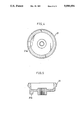
- FIG. 4 is a front elevation indicating the operating wheel of the lever type hoist.
- FIG. 5 is a traverse sectional view of the operating wheel.
- FIG. 1 and FIG. 2 indicate a lever type hoist of this invention.
- This lever type hoist is provided with a hoist body 1 constituted by a pair of parallel side plates 1a, 1b and a load sheave 2 held rotatably between those side plates 1a, 1b by bearings 3, 3.
- the load sheave 2 has a shaft hole 2a provided along its axis and a drive shaft 4 inserted in that hole.
- a gear case 5 is mounted and one end of the drive shaft 4 protrudes into the gear case 5. The other end of the drive shaft 4 protrudes to outside of the other side plate 1b.
- the transmission of rotation between the drive shaft 4 and the load sheave 2 is performed by connecting a pinion 6 and a gear 7 through a geared transmission system 8.
- the pinion 6 is fixed to one end of the drive shaft 4 and the gear 7 is fixed to the shaft part of the load sheave 2.
- the geared transmission system 8 is constituted by a plural number of gears which are rotatably supported by shaft between the side plate la and the gear case 5.
- the first right-handed screw 4a and the second right-handed screw 4b are formed in succession from the side closer to the side plate 1b.
- the first right-handed screw 4a is screw connected and fixed with a pressure receiving member 9 while the second right-handed screw 4b is screw connected to a presser drive member 15.
- the pressure receiving member 9 is constituted by a disk 9a and a boss 9b put together.
- the disk 9a is formed on the side plate 1b side and the boss 9b is formed in a way to protrude to the presser drive member 15 side.
- On the boss 9b a ratchet wheel 10 and a pair of frictional members 11, 11 are held rotatably by a round hole provided at their center.
- the ratchet wheel 10 is provided for prevention of reverse rotation while the pair of frictional members 11, 11 get in contact with the both faces of the ratchet wheel 10 in a way to be pressed against the latter.
- the ratchet wheel 10 and the pair of frictional members 11, 11 are pressed against the disk 9b of the pressure receiving member 9 by the pressing force in axial direction of the presser drive member 15.
- a reinforcing spring 16 is provided between the pressure receiving member 9 and the presser drive member 15.
- the reinforcing spring 16 adds a force in a direction to separate the pressure receiving member 9 and the presser drive member 15 from each other, and the presser drive member 15 presses the ratchet wheel 10 and the pair of frictional members 11, 11 against the disk 9b of the pressure receiving member 9 in resistance to the force of the reinforcing spring 16.
- the ratchet 12 is supported by a shaft 13 protruding from the side plate 1b and is linked with the ratchet wheel 1 by the springy force of a resilient 14 mounted on the shaft 13. This enables the ratchet wheel 10 to rotate only in the direction of lifting of the load sheave 2.
- the ratchet wheel 10, the pair of frictional member 11, 11 and the ratchet 12 constitute a drive force transmission mechanism which transmits the rotational force in the direction of lifting of the presser drive member 15 to the pressure receiving member 9.
- the presser drive member 15 forms on its external end face a first boss 15a of a large diameter and a second boss 15b of a small diameter is formed on the end face of the first boss 15a.
- a plural number (3 pieces in the illustrated example) of notches 15c are provided at equal intervals in the circumferential direction.
- a male screw 15d is formed on the circumferential face of the second boss 15b.
- a conical frictional member 17 is hollow and its circumferential face is formed in a conical face having a prescribed vertical angle.
- a collar 17d is formed inwardly in the radial direction and a round hole 17a is formed at the inner end of this collar 17d.
- the first boss 15a of the presser drive member 15 is inserted in the round hole 17a.
- On the inner circumferential face of this round hole 17a a plurality of projections 17b are provided. Those projection 17b are connected respectively with the notches 15c, 15c,--provided on the first boss 15a to constitute a spline connection.
- three cutouts 17c in axial direction are provided at equal intervals in the circumferential direction.
- the conical frictional member 17 is fitted in a conical hole 18b of a rotational force transmitting member 18 and is pressed inwardly in the axial direction by a reinforcing member 19.
- a gear 18a On the circumferential face of the rotational force transmitting member 18, a gear 18a is formed.
- the reinforcing member 19 is tightened by a nut member 20 screw connected to the second boss 15b and the conical frictional member 17 is pressed inwardly in the axial direction.
- an operating wheel 21 is connected by spline to a spline 4c formed on the drive shaft 4.
- the operating wheel 21 is prevented from falling from the drive shaft 4 by a nut 22.
- the nut 22 is screw connected to a small diameter screw 4d formed at the small diameter part at the tip of the drive shaft 4.
- a projection for connection 21a is provided facing the large diameter side of the conical frictional member 17. This projection for connection 21a is connected to one of the concavities for connection 17c, 17c,--of the conical frictional member 17.
- the length in the circumferential direction of the projection 21a of the operating wheel 21 is short compared with the length in the circumferential direction of the cutouts 17c, 17c,--of the conical frictional member 17. For that reason, when the operating wheel 21 is rotated in the lowering direction together with the drive shaft 4 and the conical frictional member 17 is rotated in the lowering direction at a rotational speed slightly slower than the drive shaft 4, the conical frictional member 17 moves to the pressure receiving member 9 side along the drive shaft 4 until the time when the projection 21a of the operating wheel 21 contacts the side wall of the cutouts 17c of the conical frictional member 17.
- a brake cover 23 is mounted on the surface side of the side plate 1b.
- This brake cover 23 covers the entire part of the pressure receiving member 9, the ratchet wheel 10 and the ratchet 12 and covers a part of the presser drive member 15.
- a flange 23a is formed and this part of flange 23a is screwed to the side plate 1b.
- a cylindrical part 23b is formed on the other end of the brake cover 23. The cylindrical part 23b is located close to the circumferential face of the presser drive member 15.
- the cylindrical part 23b holds an operating lever 24 rotatably against both the brake cover 23 and the operating wheel 21.
- the operating lever 24 drives the presser drive member 15 to rotate in either the lifting direction or the lowering direction through the rotational force transmitting member 18 and the conical frictional member 17.
- This operating lever 24 consists of an inner cover 24A and an outer cover 24B of steel, the outer cover 24B being fitted on the outside of the inner cover 24A and the peripheral part of those two covers being connected to each other by means of a plural number of bolts 25.
- the peripheral cover of those two covers 24A and 24B covers the entire part of the rotational force transmitting member 18.
- an inner cylindrical part 24a is provided facing the cylindrical part 23b of the brake cover 23 and this inner cylindrical part 24a is inserted in the inner side of the cylindrical part 23b and held there in a rotatable condition.
- a connecting member 26 prevents disconnection with the brake cover 23.
- This connecting member 26 is mounted on the inner face of the inner cylindrical part 24a and is bent to the cylindrical part 23b side of the brake cover 23.
- an outer cylindrical part 24b is formed on the outside in axial direction of the outer cover 24B.
- the outer cylindrical part 24b covers the connecting portion of the concavities for connection 17c of the conical frictional member 17 and the projection for connection 21a of the operating wheel 21.
- the rotational direction selecting claw 27 switches the rotational direction of the rotational force transmitting member 18, the conical frictional member 17 and the presser drive member 15 to either lifting direction or lowering direction.
- the rotational direction selecting claw 27 is fixed to a supporting shaft 28.
- the supporting shaft 28 is held rotatably by the operating lever 24 and protrudes at one end to outside from the operating lever 24. This protruding part of the supporting shaft 28 is provided with a handle 29 for switching.
- the rotational direction selecting claw 27 is selectively switched to two connecting positions (lifting position and lowering position) to be connected to the gear 18a of the rotational force transmitting member 18 and to a neutral position not to be connected to the gear 18a.
- the reciprocating rotational operation of the operating lever 24 is transmitted to the rotational force transmitting member 18 through the rotational direction selecting claw 27.
- the rotational force transmitting member 18 rotates the presser drive member 15 in either the lifting position or the lowering position through the conical frictional member 17.
- the neutral position the rotational force transmitting member 18 does not turn in any direction because it is disconnected from the rotational direction selecting claw 27 of the operating lever 24.
- the lower end part of the rotational direction selecting claw 27 is pressed springily upward by a positioning member 30 reinforced by a coil spring 31. And, under the pressing force of the coil spring 31, the rotational direction selecting claw 27 is held springily at either the two connecting positions or the neutral position.
- An upper hook 33 for lifting the hoist body 1 is attached to a connecting shaft 32 which connects the side plates 1a, 1b.
- a lower hook 35 for lifting the baggage is provided at the lower end of the load chain 34.
- the rotational force transmitting member 18 will rotate the conical frictional member 17 in the lifting direction through a conical face contact with the conical frictional member 17 due to the pressing force of the reinforcing member 19 within the established rated load.
- This rotational force is transmitted to the presser drive member 15 with the connection between the convexities for connection 17b of the conical frictional member 17 and the notches 15c of the presser drive member 15.
- the presser drive member 15 spirally progresses to inside in axial direction on this right-handed screw 4b of the drive shaft 4 to rotate the pressure receiving member 9 in unison through the ratchet wheel 10 and the frictional members 11, 11 on both sides, causing the drive shaft 4 to rotate in the lifting direction (clockwise direction seen from the operating wheel 21 side).
- the rotational force of the drive shaft 4 is transmitted to the load sieve 2 through the geared transmission system 8 connected with the pinion 6 at one end of the drive shaft 4.
- the load sieve 2 rotates in the same direction as the drive shaft 4.
- the presser drive member 15 will be made to move in the direction not to press the ratchet wheel 10 and the frictional members 11, 11 by the rotational force transmitting member 18 and the conical frictional member 17, allowing the pressure receiving member 9 and the drive shaft 4 to turn in the lowering direction by a certain angle against the ratchet wheel 10.
- the baggage within the rated load hung at the lower hook 35 will be lowered intermittently with repetitions of two-way operations of the operating lever 24.
- the drive shaft 4 is also rotated in the same direction by the geared transmission system 8 which is engaged with the gear 7 of the load sheave 2.
- the presser drive member 15 is rotated at a speed somewhat slower than the drive shaft 4 because it is pressed outwardly in the axial direction by the reinforcing member 16 mounted between the presser drive member 15 and the pressure receiving member 19 and its frictional force with the frictional members 11 is small.
- the presser drive member 15 screw connected with the right-handed screw 4b of the drive shaft 4 is moved toward the operating wheel 21 together with the conical frictional member 17 which is linked with the notch 15c of the first boss 15a.
- the rotational force transmitting member 18 which is in contact with both the presser drive member 15 and the conical frictional member 17 also moves toward the operating wheel 21 to come closer to the inner face of the external cover 24B of the operating lever 24 and other component members.
- This invention provides excellent operating characteristics as described below.
- the conical face of the conical frictional member connected to the presser drive member is put in frictional contact in the conical hole of the rotational force transmitting member by a pressing force set by a reinforcing member. For that reason, if the baggage hung at the lower hook of the load chain has become heavier than the rated load, the rotational force transmitting member runs idle as it cannot rotate the conical frictional member and the presser drive member on which a load larger than the rated load is acting, even if you try to rotate the rotational force transmitting member in the lifting direction. Consequently, lifting of a baggage heavier than the rated load is automatically prevented to ensure the safety of work.
- the concavity for connection on the large diameter side of the conical frictional member and the projection for connection of the operating wheel facing it are positioned in such a way as to get in touch with each other before the rotational force transmitting member gets in contact with the external cover of the operating lever and other component members.
- the rotational force transmitting member also rotates in unison with the drive shaft by the operating wheel before it gets in contact with the external cover of the operating lever and other component members. Therefore, it becomes possible to make a smooth free rotation of the load sieve continuously with a small pulling force, thus enabling a rapid movement of the lower hook.
Landscapes
- Engineering & Computer Science (AREA)
- Mechanical Engineering (AREA)
- One-Way And Automatic Clutches, And Combinations Of Different Clutches (AREA)
- Hand Tools For Fitting Together And Separating, Or Other Hand Tools (AREA)
- Load-Engaging Elements For Cranes (AREA)
- Mechanical Operated Clutches (AREA)
Applications Claiming Priority (2)
| Application Number | Priority Date | Filing Date | Title |
|---|---|---|---|
| JP2-282669 | 1990-10-19 | ||
| JP2282669A JPH0633155B2 (ja) | 1990-10-19 | 1990-10-19 | レバー式捲上機 |
Publications (1)
| Publication Number | Publication Date |
|---|---|
| US5088694A true US5088694A (en) | 1992-02-18 |
Family
ID=17655515
Family Applications (1)
| Application Number | Title | Priority Date | Filing Date |
|---|---|---|---|
| US07/672,109 Expired - Lifetime US5088694A (en) | 1990-10-19 | 1991-03-19 | Lever type hoist |
Country Status (6)
| Country | Link |
|---|---|
| US (1) | US5088694A (de) |
| JP (1) | JPH0633155B2 (de) |
| BE (1) | BE1005350A3 (de) |
| DE (1) | DE4110665C2 (de) |
| GB (1) | GB2248818B (de) |
| SE (1) | SE508605C2 (de) |
Cited By (12)
| Publication number | Priority date | Publication date | Assignee | Title |
|---|---|---|---|---|
| EP0583550A2 (de) * | 1992-08-17 | 1994-02-23 | H.H.H. Manufacturing Co. | Kettenflaschenzug mit Betätigungshebel |
| EP0585091A1 (de) * | 1992-08-27 | 1994-03-02 | Elephant Chain Block Company Limited | Freie Drehung-Steuerungsvorrichtung für ein Hebe- und Zuggerät |
| US5305989A (en) * | 1991-09-20 | 1994-04-26 | Elephant Chain Block Company Limited | Hoist and traction machine with free rotation control |
| US5351937A (en) * | 1991-09-20 | 1994-10-04 | Elephant Chain Block Company Limited | Hoist and traction machine with free rotation control |
| WO1996006228A1 (en) * | 1994-08-19 | 1996-02-29 | General Railway Signal Corporation | Switch machine |
| US5582370A (en) * | 1994-08-19 | 1996-12-10 | General Railway Signal Corporation | Switch machine with ratchet mechanism on hand throw mechanism |
| US6406001B1 (en) * | 1998-12-02 | 2002-06-18 | Elephant Chain Block Co., Ltd. | Chain lever hoist |
| US6517054B2 (en) * | 2001-04-23 | 2003-02-11 | Vital Kogyo Kabushiki Kaisha | Lever hoist with overload preventing device |
| US20140124720A1 (en) * | 2011-03-24 | 2014-05-08 | Shinji Hagihara | Hoist equipped with power-off type electromagnetic brake |
| US20150014615A1 (en) * | 2012-03-08 | 2015-01-15 | Kito Corporation | Hand operated pulling and lifting hoist |
| US9610884B1 (en) * | 2016-01-11 | 2017-04-04 | Cottrell, Inc. | Vehicle and cargo ratcheting tie down apparatus and system |
| US9994433B2 (en) * | 2016-02-18 | 2018-06-12 | Jpw Industries Inc. | Brake/clutch device for manual hoist |
Families Citing this family (4)
| Publication number | Priority date | Publication date | Assignee | Title |
|---|---|---|---|---|
| GB2252289B (en) * | 1991-02-01 | 1994-07-06 | Vital Chain Block Mfg | Lever-operated hoist |
| JPH0745518Y2 (ja) * | 1992-12-18 | 1995-10-18 | 象印チエンブロック株式会社 | 巻上・牽引機 |
| JP2782061B2 (ja) * | 1996-08-13 | 1998-07-30 | バイタル工業株式会社 | レバー式捲上機 |
| GB2410484B (en) * | 2005-03-29 | 2006-05-31 | Comeup Ind Inc | Brake apparatus for winch |
Citations (3)
| Publication number | Priority date | Publication date | Assignee | Title |
|---|---|---|---|---|
| US4469308A (en) * | 1982-03-11 | 1984-09-04 | Kabushiki Kaisha Kito | Lever hoist |
| US4474360A (en) * | 1982-06-09 | 1984-10-02 | Kabushiki Kaisha Kito | Idling device for lever hoist |
| US4768754A (en) * | 1986-09-10 | 1988-09-06 | Vital Kogyo Kabushiki Kaisha | Manual hoist with overload preventer |
Family Cites Families (7)
| Publication number | Priority date | Publication date | Assignee | Title |
|---|---|---|---|---|
| FR1423274A (fr) * | 1965-01-29 | 1966-01-03 | Heinrich De Fries G M B H | Dispositif de sécurité pour empêcher la surcharge des appareils de levage à commande manuelle |
| US4251060A (en) * | 1977-12-20 | 1981-02-17 | Kabushiki Kaisha Kito | Hand hoist |
| JPS60202093A (ja) * | 1984-03-22 | 1985-10-12 | バイタル工業株式会社 | 捲上機の過負荷防止装置 |
| JPS6218625U (de) * | 1985-07-18 | 1987-02-04 | ||
| JPH0344788Y2 (de) * | 1987-02-18 | 1991-09-20 | ||
| JPH02178196A (ja) * | 1988-12-28 | 1990-07-11 | Nitsuchi:Kk | 牽引巻上機の空転装置 |
| JPH02249895A (ja) * | 1989-03-24 | 1990-10-05 | Nitsuchi:Kk | 牽引巻上機の空転装置 |
-
1990
- 1990-10-19 JP JP2282669A patent/JPH0633155B2/ja not_active Expired - Fee Related
-
1991
- 1991-03-19 US US07/672,109 patent/US5088694A/en not_active Expired - Lifetime
- 1991-03-21 GB GB9106034A patent/GB2248818B/en not_active Expired - Fee Related
- 1991-03-22 SE SE9100872A patent/SE508605C2/sv not_active IP Right Cessation
- 1991-04-02 BE BE9100300A patent/BE1005350A3/fr not_active IP Right Cessation
- 1991-04-03 DE DE4110665A patent/DE4110665C2/de not_active Expired - Fee Related
Patent Citations (3)
| Publication number | Priority date | Publication date | Assignee | Title |
|---|---|---|---|---|
| US4469308A (en) * | 1982-03-11 | 1984-09-04 | Kabushiki Kaisha Kito | Lever hoist |
| US4474360A (en) * | 1982-06-09 | 1984-10-02 | Kabushiki Kaisha Kito | Idling device for lever hoist |
| US4768754A (en) * | 1986-09-10 | 1988-09-06 | Vital Kogyo Kabushiki Kaisha | Manual hoist with overload preventer |
Cited By (22)
| Publication number | Priority date | Publication date | Assignee | Title |
|---|---|---|---|---|
| US5351937A (en) * | 1991-09-20 | 1994-10-04 | Elephant Chain Block Company Limited | Hoist and traction machine with free rotation control |
| US5398912A (en) * | 1991-09-20 | 1995-03-21 | Elephant Chain Block Company Limited | Hoist including brake cover and operating lever coupling |
| US5305989A (en) * | 1991-09-20 | 1994-04-26 | Elephant Chain Block Company Limited | Hoist and traction machine with free rotation control |
| US5647576A (en) * | 1992-08-17 | 1997-07-15 | H.H.H. Manufacturing Co. | Chain lever hoist |
| CN1044895C (zh) * | 1992-08-17 | 1999-09-01 | 株式会社3H | 链式杠杆葫芦 |
| EP0583550A3 (en) * | 1992-08-17 | 1994-05-25 | Hhh Mfg Co | Chain lever hoist |
| EP0583550A2 (de) * | 1992-08-17 | 1994-02-23 | H.H.H. Manufacturing Co. | Kettenflaschenzug mit Betätigungshebel |
| US5538222A (en) * | 1992-08-17 | 1996-07-23 | H.H.H. Manufacturing Co. | Chain lever hoist |
| US5472171A (en) * | 1992-08-27 | 1995-12-05 | Elephant Chain Block Company Limited | Free rotation control apparatus for a hoist and traction machine |
| EP0585091A1 (de) * | 1992-08-27 | 1994-03-02 | Elephant Chain Block Company Limited | Freie Drehung-Steuerungsvorrichtung für ein Hebe- und Zuggerät |
| WO1996006228A1 (en) * | 1994-08-19 | 1996-02-29 | General Railway Signal Corporation | Switch machine |
| US5582370A (en) * | 1994-08-19 | 1996-12-10 | General Railway Signal Corporation | Switch machine with ratchet mechanism on hand throw mechanism |
| AU704448B2 (en) * | 1994-08-19 | 1999-04-22 | General Railway Signal Corporation | Switch machine |
| US6406001B1 (en) * | 1998-12-02 | 2002-06-18 | Elephant Chain Block Co., Ltd. | Chain lever hoist |
| US6517054B2 (en) * | 2001-04-23 | 2003-02-11 | Vital Kogyo Kabushiki Kaisha | Lever hoist with overload preventing device |
| US20140124720A1 (en) * | 2011-03-24 | 2014-05-08 | Shinji Hagihara | Hoist equipped with power-off type electromagnetic brake |
| US9181071B2 (en) * | 2011-03-24 | 2015-11-10 | Kito Corporation | Hoist equipped with power-off type electromagnetic brake |
| US20150014615A1 (en) * | 2012-03-08 | 2015-01-15 | Kito Corporation | Hand operated pulling and lifting hoist |
| AU2013228672B2 (en) * | 2012-03-08 | 2017-04-20 | Kito Corporation | Manually operated hoisting / towing device |
| US9802798B2 (en) * | 2012-03-08 | 2017-10-31 | Kito Corporation | Hand operated pulling and lifting hoist |
| US9610884B1 (en) * | 2016-01-11 | 2017-04-04 | Cottrell, Inc. | Vehicle and cargo ratcheting tie down apparatus and system |
| US9994433B2 (en) * | 2016-02-18 | 2018-06-12 | Jpw Industries Inc. | Brake/clutch device for manual hoist |
Also Published As
| Publication number | Publication date |
|---|---|
| SE508605C2 (sv) | 1998-10-19 |
| GB9106034D0 (en) | 1991-05-08 |
| JPH04159999A (ja) | 1992-06-03 |
| DE4110665C2 (de) | 1995-07-06 |
| GB2248818B (en) | 1994-01-19 |
| SE9100872L (sv) | 1992-04-20 |
| BE1005350A3 (fr) | 1993-07-06 |
| JPH0633155B2 (ja) | 1994-05-02 |
| GB2248818A (en) | 1992-04-22 |
| SE9100872D0 (sv) | 1991-03-22 |
| DE4110665A1 (de) | 1992-04-23 |
Similar Documents
| Publication | Publication Date | Title |
|---|---|---|
| US5088694A (en) | Lever type hoist | |
| US4469308A (en) | Lever hoist | |
| US4813303A (en) | Power drive speed reducer | |
| US6554255B2 (en) | Lifting gear | |
| US5238226A (en) | Lever operated hoist | |
| US4768754A (en) | Manual hoist with overload preventer | |
| US4390161A (en) | Winch drive and brake mechanism | |
| US4664357A (en) | Overload avoiding arrangement for a hoist | |
| EP0318414B1 (de) | Antrieb mit zwei Geschwindigkeiten für motorgetriebene Gewindeschneidmaschine | |
| KR960005022B1 (ko) | 레버식 권상견인기 | |
| US5156377A (en) | Lever-operated hoist | |
| JPS6316715Y2 (de) | ||
| US4986400A (en) | Bi-directional spring clutch for reducing worm gear drive | |
| JPH06271290A (ja) | レバー式牽引巻上機における遊転装置 | |
| US6059267A (en) | Lever hoist | |
| JP3086874B2 (ja) | チェーンレバーホイスト | |
| US5769398A (en) | Lever hoist | |
| EP0289305B1 (de) | Freifallwinde | |
| US4420144A (en) | Manual hoisting and pulling apparatus | |
| US4479635A (en) | Idling device for lever hoist | |
| EP0131380A1 (de) | Hebezeug | |
| US4819913A (en) | Lever type hoisting machine | |
| US5018682A (en) | Fishing reel having a spool shaft supported at both ends thereof | |
| US4436333A (en) | Hand operated hoist having improved means controlling free rotation of a load sheave | |
| JPH05238680A (ja) | 電動巻上装置 |
Legal Events
| Date | Code | Title | Description |
|---|---|---|---|
| AS | Assignment |
Owner name: VITAL KOGYO KABUSHIKI KAISHA, JAPAN Free format text: ASSIGNMENT OF ASSIGNORS INTEREST.;ASSIGNOR:NISHIMURA, YOSAKU;REEL/FRAME:005656/0553 Effective date: 19910311 |
|
| STCF | Information on status: patent grant |
Free format text: PATENTED CASE |
|
| FEPP | Fee payment procedure |
Free format text: PAYOR NUMBER ASSIGNED (ORIGINAL EVENT CODE: ASPN); ENTITY STATUS OF PATENT OWNER: SMALL ENTITY |
|
| FPAY | Fee payment |
Year of fee payment: 4 |
|
| FEPP | Fee payment procedure |
Free format text: PAYER NUMBER DE-ASSIGNED (ORIGINAL EVENT CODE: RMPN); ENTITY STATUS OF PATENT OWNER: SMALL ENTITY Free format text: PAYOR NUMBER ASSIGNED (ORIGINAL EVENT CODE: ASPN); ENTITY STATUS OF PATENT OWNER: SMALL ENTITY |
|
| FPAY | Fee payment |
Year of fee payment: 8 |
|
| FEPP | Fee payment procedure |
Free format text: PAYER NUMBER DE-ASSIGNED (ORIGINAL EVENT CODE: RMPN); ENTITY STATUS OF PATENT OWNER: SMALL ENTITY Free format text: PAYOR NUMBER ASSIGNED (ORIGINAL EVENT CODE: ASPN); ENTITY STATUS OF PATENT OWNER: SMALL ENTITY |
|
| FPAY | Fee payment |
Year of fee payment: 12 |