US5077670A - System and method applicable to vehicles for communicating between data processing stations - Google Patents
System and method applicable to vehicles for communicating between data processing stations Download PDFInfo
- Publication number
- US5077670A US5077670A US07/454,542 US45454289A US5077670A US 5077670 A US5077670 A US 5077670A US 45454289 A US45454289 A US 45454289A US 5077670 A US5077670 A US 5077670A
- Authority
- US
- United States
- Prior art keywords
- echoback
- command
- signal
- master station
- control unit
- Prior art date
- Legal status (The legal status is an assumption and is not a legal conclusion. Google has not performed a legal analysis and makes no representation as to the accuracy of the status listed.)
- Expired - Lifetime
Links
- 238000012545 processing Methods 0.000 title claims description 29
- 238000000034 method Methods 0.000 title claims description 17
- 238000004891 communication Methods 0.000 claims abstract description 67
- 230000004044 response Effects 0.000 claims abstract description 19
- 230000005540 biological transmission Effects 0.000 claims description 9
- 238000012790 confirmation Methods 0.000 claims description 2
- 239000000446 fuel Substances 0.000 description 5
- 238000002347 injection Methods 0.000 description 5
- 239000007924 injection Substances 0.000 description 5
- 238000003745 diagnosis Methods 0.000 description 3
- 230000001364 causal effect Effects 0.000 description 2
- 238000010187 selection method Methods 0.000 description 2
- 230000009471 action Effects 0.000 description 1
- 230000008901 benefit Effects 0.000 description 1
- 238000011161 development Methods 0.000 description 1
- 230000018109 developmental process Effects 0.000 description 1
- 238000010586 diagram Methods 0.000 description 1
- 230000007257 malfunction Effects 0.000 description 1
- 238000012986 modification Methods 0.000 description 1
- 230000004048 modification Effects 0.000 description 1
- 239000004065 semiconductor Substances 0.000 description 1
Images


Classifications
-
- H—ELECTRICITY
- H04—ELECTRIC COMMUNICATION TECHNIQUE
- H04L—TRANSMISSION OF DIGITAL INFORMATION, e.g. TELEGRAPHIC COMMUNICATION
- H04L1/00—Arrangements for detecting or preventing errors in the information received
- H04L1/12—Arrangements for detecting or preventing errors in the information received by using return channel
- H04L1/14—Arrangements for detecting or preventing errors in the information received by using return channel in which the signals are sent back to the transmitter to be checked ; echo systems
Definitions
- the present invention relates to a system and method for communicating between data processing stations such as a master station (i.e., diagnostic device) and various substations (i.e., electronic control units installed in a vehicle) to diagnose trouble in one or each of the electronic control units (ECUs), e.g., a control unit for controlling, e.g., a vehicular engine.
- a master station i.e., diagnostic device
- various substations i.e., electronic control units installed in a vehicle
- ECUs electronice.e., a control unit for controlling, e.g., a vehicular engine.
- ECUs electronice control units
- a master station constituting an off-board diagnostic device which carries out the off-board diagnosis and which is capable of making precise, high-quality diagnoses has been developed.
- the master station selects a desired electronic control unit from among the plurality of electronic control units installed in the vehicle, transmits a diagnostic control command to the selected electronic control unit, and receives returned data from the selected electronic control unit in response to the diagnostic control command.
- the master station initially transmits an initializing command to set each electronic control unit via a communication circuit located between the master station and the plurality of the electronic control units and transmits an initializing command to place each electronic control unit in a receipt wait, state for a system call command which will select the desired electronic control unit from among the plurality of electronic control units.
- the master station Upon transmission of the initializing command with the communication circuit initialized and each electronic control unit placed in the receipt wait state for the system call command, the master station transmits the system call command to select only the desired electronic control unit so that a data link from the master station to the selected electronic control unit is established.
- the master station transmits a control command such as a parameter set command, the control command being issued to command to cause the selected electronic control unit to a desired control operation.
- the selected control unit receives the control command and then returns an echoback signal to the master station, the echoback signal being logically opposite to the control command.
- the control command is followed by two information bytes, consecutively transmitted for each predetermined interval of time. At this time, an item to be controlled is set in a first information byte and a controlled variable on the item to be controlled is set in a subsequent second information byte. Then, the master station monitors the response characteristic of the vehicle, e.g., the vehicular engine controlled by the ECU to compare that the vehicle response correlates with the ECU parameter specified by the control command.
- the selected ECU receives two information bytes, i.e., first and second information bytes and returns echoback signals whose bits are opposite to those of the two information bytes back to the master station whenever the selected control unit receives the two information bytes. Then, the master station confirms that the inverted echoback signals are received.
- the normally operating electronic control unit when the selected electronic control unit receives the first and second information bytes transmitted from the master station after the control command, the normally operating electronic control unit returns the echoback signals whose bit contents are logically opposite to those of the two information bytes back to the master station.
- the non-selected control unit erroneously responds to the system call command.
- the master station cannot determine that the non-selected control unit erroneously outputs the echoback signal.
- a communication system comprising a) a plurality of subordinate data processing stations; b) a master data processing station; and c) a communication circuit interconnected between the master station and the plurality of subordinate stations, the master data processing station transmitting various commands and transmitting at least two information signals on a predetermined operation of any one of the subordinate data processing stations to the communication circuit, any one of the subordinate data processing stations which is assigned to communicate with the master station transmitting a first echoback signal to the master station to inform the master station of the receipt of each command and transmitting a second echoback signal to the master station of the receipt of each information signal, and bit contents of the second echoback signals being determined depending on whether the bit contents of the first echoback signals are the same as or logically opposite to those of the respectively corresponding commands.
- a data communication system comprising: a) a plurality of electronic control units (ECUs), each control unit carrying out a predetermined control operation to a controlled object; b) an off-board diagnostic device; c) a communication circuit interconnected between the diagnostic device and each control unit; d) first means, provided in the diagnostic device, for transmitting an initializing command via the communication circuit to the plurality of electronic control units to initialize the plurality of electronic control units so as to place the electronic control units in a receipt wait state for a system call command, transmitting the system call command via the communication circuit to select a desired one of the electronic control units to communicate between the selected control unit and the diagnostic device, and transmitting a control command to the selected control unit to execute a predetermined control operation and thereafter transmitting at least two information signals related to the control command and indicating the contents of the predetermined control operation; and e) second means, provided in the control unit selected in response to the system call command, for transmitting a first echoback signal to the
- the above-described object can also be achieved by providing a communication method, comprising the steps of a) providing a plurality of subordinate data processing stations; b) providing a master data processing station; c) providing a communication circuit interconnected between the master station and the plurality of subordinate stations; d) causing the master station to transmit various commands and transmit at least two information signals to the communication circuit, the information signals being related to a predetermined operation for any one of the subordinate data processing stations which is assigned to communicate with the master station; and e) causing the subordinate station to return a first echoback signal to the master station to inform the master station of the receipt of each command and to return a second echoback signal to the master station to inform the master station of the receipt of each information signal, bit contents of each second echoback signal being determined depending on whether the bit contents of each first echoback signal is the same as or logically opposite to that of the corresponding command.
- FIG. 1 is a schematic circuit block diagram of a system for communicating between each station applicable to a vehicle in a preferred embodiment according to the present invention.
- FIG. 2 is an explanatory view of a data format used in the communicating system in the preferred embodiment shown in FIG. 1.
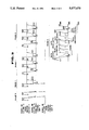
- FIG. 3 is a timing chart indicating an operation of the communicating system shown in FIG. 1.
- FIG. 4 is a table indicating an operation and action of the communicating system shown in FIG. 1.
- FIG. 5 is a timing chart of signals indicating an operation of the communication system in another preferred embodiment.
- FIG. 1 shows a preferred embodiment of a system for communicating between each data processing station applicable to a vehicle.
- a plurality of control units 1, 3, --including electronic control units (ECU) such as engine control unit, A/T (automatic transmission) control unit, and so on which constitute a control portion of the vehicle are interconnected to a signal line 5, the signal line 5 having an ECU data transmission line Tx, ECU data reception line Rx, and clock line CLK.
- a master station 9 is connected to the plurality of control units 1, 3,--via the signal line 5 and a connector 7.
- the master station 9 constitutes an off-board diagnostic device which diagnoses the control portion of the vehicle having the plurality of the control units, 1, 3,--.
- the master station 9 includes a ten key pad 11, e.g., a keyboard, for inputting various kinds of information, a display 13 for displaying diagnostic information, a power supply switch 15, and an end key 17 for terminating a series of diagnostic operations to be described later.
- a ten key pad 11 e.g., a keyboard
- a display 13 for displaying diagnostic information
- a power supply switch 15 for terminating a series of diagnostic operations to be described later.
- FIG. 1 shows only two control units 1 and 3 (first and second control units), various kinds of other control units may be installed.
- the master station 9 selects a desired one of the plurality of control units 1 and 3, transmits various diagnostic commands to diagnose the selected control unit, and receives the responding information to the corresponding commands so as to carry out the trouble diagnoses for the respective control units.
- an NRZ (Non-Return to Zero) method is preferably used as a transmission path coding.
- a data modulation system an UART (Universal Asynchronous Receiver/Transmitter) is built in the communication circuit to facilitate the ECU data transmission and reception.
- UART Universal Asynchronous Receiver/Transmitter
- a one-bit start bit (“0") is added to a head portion, then, an eight-bit data is inserted into a portion after the start bit, and finally a one-bit stop bit (“1") is added after the eighth bit of data, as shown in FIG. 2, thus constituting one command and information byte used for each communication.
- a polling/selection method is used as a transmission control method between the master station and each control unit, with the master station 9 being a main station and each control unit being a subordinate station. Because the polling/selection method employs point-to-point communication between the off-board diagnostic, device (master station) and the ECU selected, it has the advantage of more simpler protocol and ECU software than a multi-master method.
- the master station 9 selects a desired control unit from among the plurality of control units 1 and 3 on the basis of the modulation method and transmission control method, transmits various types of commands and information bytes carrying out various diagnoses for the selected control unit, and receives an echoback signal responding to the diagnostic commands to carry out the diagnostic operation.
- Control procedures to execute selection and diagnostic operation are divided into four phases 0 through 3 as shown in the following Table.
- each phase 0 through 3 defined in the above-described Table is denoted in a time axis in the lateral direction of the timing chart of FIG. 3 and the control procedures by means of the master station 9 are sequentially executed in accordance with each phase.
- the connector 7 connects the master station 9 to each control unit 1 and 3, as described in an item of man (machine operation) of FIG. 4, and thereafter each power supply of both master station and each control unit 1 and 3 is turned on so as to operate the system for communicating between each station.
- the master station 9 With the power supply turned on and the system in operation, the master station 9 enters the Phase 0. Then, "1. First Control Unit”, “2, Second Control Unit”, --are displayed which indicate all control units presently connected to the master station 9, as denoted by 41 in FIG. 4.
- the master station 9 transmits an initializing command INIT at a time t1 of FIG. 3 in order to initialize the communication circuit and terminate a data link as will be described later.
- Each control unit 1 and 3 upon receipt of the initializing command INIT, enters a receipt wait state for a system call command SC (i) to be described later, and the signal line 5, particularly, the data transmission line Tx thereof enters an idle state so that the circuit constituted by the signal line 5 is initialized.
- the established control unit terminates the communication and enters the receipt wait state for the system call command SC (i).
- the master station 9 enters Phase 1. In this phase, the master station 9 is operated to select the desired control unit to be diagnosed from among the control units 1 and 3 by the operator through the ten key pad 11.
- the ten key pad 11 of the master station 9 is used to select a number assigned to the desired control unit.
- One of system call commands SC (i) which corresponds to the selected number of the control unit is transmitted at a time shown by t3 of FIG. 3.
- FIG. 3 shows a case where the first control unit 1 is selected and the system call command SC (i) is transmitted from the master station 9 to the first control unit 1.
- the selected first control unit 1 When the system call command SC (i) transmitted from the master station 9 is received by the selected first control unit 1, the selected first control unit 1 transmits its echoback signal SC (i) which is a reversed signal (logically opposite) of the corresponding system call command SC (i) in order to inform the master station 9 of the receipt of the system select command SC (i) at a time denoted by t4 of FIG. 3.
- the master station 9 receives the reversed echoback signal SC (i) so that the reception of the system call command is confirmed by the selected control unit (first control unit 1).
- the master station 9 confirms that the reversed echoback signal is derived from the first control unit 1, the data link between the master station 9 and first control unit 1 is established.
- the other control units i.e., the second control unit 3 not selected is returned to the initializing command wait state and is held in the initializing command wait state until the subsequent initializing command (INIT) is received.
- the master station enters the Phase 2 to set a diagnostic mode.
- a list of diagnostic functions which can be executed by the master station 9 are displayed on the display 13 of the master station 9 as denoted by 42 of FIG. 4.
- the master station 9 transmits one of the mode setting commands.
- Various commands are provided in the mode set commands, i.e., self-defined commands and control commands such as a parameter set command PS having, e.g., information bytes subsequent to the parameter set command PS.
- the parameter set command PS is, e.g., a command to command the engine control unit 1 to set the engine in a particular state and, e.g., two information bytes subsequent to the command are continuously transmitted, at a predetermined time interval for each byte.
- the master station 9 transmits two information bytes, the first information byte indicating "engine idling revolution speed" and the second information byte indicating" 1500 R. P. M.”.
- the operator selects the case where the engine idling revolution speed is set at 1500 R. P. M. as the diagnostic mode described above.
- the operator selects the diagnostic mode for the parameter set command from the display 13 of the master station 9 through the ten key pad 11.
- the operator may specify the "engine revolution speed” and "1500 R.P.M.” as the information bytes subsequent to the parameter set command through the ten key pad 11.
- the display 13 of the master station 9 displays "revolution speed” and "1500 R. P. M.”, as shown by 43 of FIG. 4.
- the parameter set command PS is transmitted to the first control unit 1 from the master station 9, as shown by time t5 of FIG. 3.
- the first control unit 1 upon receipt of the parameter set command PS from the master station 9, returns back the echoback signal PS which is the reversed signal of the parameter set command PS to confirm receipt of the parameter set command PS at a time denoted by t6 of FIG. 3 so that the first control unit 1 is placed in an information byte wait state.
- the master station 9 confirms that the echoback signal transmitted from the first control unit 1 is the reversed data of the previously transmitted parameter set command PS, the master station 9 transmits the first information byte Item indicating "engine revolution speed" to the first control unit 1 at a time denoted by t7 of FIG. 3.
- the first control unit 1 When the first control unit 1 receives the first information byte Item, the first control unit 1 returns back the echoback signal of the same data as the first information byte, i.e., the non-inverted echoback signal to the master station 9, at the time denoted by t8 of FIG. 3.
- the master station 9 confirms that the echoback signal from the first control unit 1 is the same as the previously transmitted first information byte, the second information byte Item indicating 1500 R. P. M. is transmitted to the first control unit 1 at the time denoted by t9 of FIG. 3.
- the first control unit 1 receives the second information byte Item and then returns back the echoback signal of the same data as the second information byte Item previously transmitted to the master station 9 at a time t10 of FIG. 3 to terminate the set of the parameter set command PS.
- the ten key pad 11 is, similarly, used to select the diagnostic mode for the parameter set command PS through the display 13 of the master station 9. Signals indicating "Fuel Injection Quantity” and numerical value corresponding to "10% increase” are keyed-in through the ten key pad 11.
- the master station 9 again transmits the parameter set command PS to the first control unit 1.
- the first control unit 1 When the parameter set command PS is again transmitted at a time denoted by t11 of FIG. 3, the first control unit 1 returns back the echoback signal, i.e., the reversed signal PS of the present parameter set command PS to the master station 9 at a time t12 of FIG. 3.
- the first control unit 1 is in the state receiving the related information bytes.
- the master station 9 Upon receipt of the echoback signal from the first control unit 1, the master station 9 transmits the first information byte indicating "the fuel injection quantity" at a time t13 of FIG. 3 and returns back the echoback signal having the same data as the first information byte to the master station 9 at a time t14 of FIG. 3.
- the second information byte Item indicating the "numerical data corresponding to 10% increase" is transmitted to the first control unit 1 at a time t15 of FIG. 3.
- the first control unit 1 returns back the echoback signal having the same data as the second information byte to the master station 9 at a time t16 of FIG. 3.
- the master station 9 sets “the engine revolution speed” to 1500 R.P.M. and ends the diagnostic mode setting such that "the fuel injection quantity is increased by 10% ".
- the master station 9 enters Phase 3 and the diagnostic execution command EX as shown in time t17 of FIG. 3 is transmitted to the first control unit 1.
- the diagnostic data returned back in this way is returned back in one frame which is constituted by the data of one-byte header, one-byte data length indicating the length of the data to be transmitted thereafter, and the diagnostic data of 254 bytes or less, for a time interval from a time t18 to time t19 in FIG. 3.
- the diagnostic data returned back from the first control unit 1 is received by the master station 9 and the received diagnostic data is displayed through the display 13 of the master station 9 as shown in FIG. 4.
- the control value is modified as prescribed and the normal operation of the relation to the engine is confirmed. It is noted that the engine revolution speed of the diagnostic data displayed on the display 13 is 1502 R. P. M. and this is determined to be a substantially normal value.
- the master station 9 Upon pushing of the end key 17, the master station 9 transmits the diagnostic termination command STP to the first control unit 1 at a time denoted by t20 of FIG. 3.
- the first control unit 1 Upon receipt of the diagnostic termination command, the first control unit 1 clears the control commands presently set and returns back an echoback signal STP which is logically opposite to the received diagnostic termination command STP to the master station 9 at a time denoted by t21 of FIG. 3.
- the diagnoses to the first control unit are terminated.
- the echoback signals for the corresponding information bytes are the same as the bit contents of the corresponding information bytes
- the echoback signals may have the bit contents logically opposite to those of the corresponding information bytes if the echoback signals for the corresponding commands have the same bit contents as the corresponding commands.
- FIG. 5 shows Phase 2, the other phases are the same as those shown in FIG. 3 except the echoback signals for the commands which are the same as the corresponding commands.
- the bit contents of the echoback signals for the corresponding information bytes are determined depending on whether the echoback signals for the corresponding commands are the same as or logically opposite to the corresponding commands. Specifically, the echoback signals for the information bytes are logically opposite to the corresponding information bytes when those for the commands associated therewith are the same as the commands, and are the same as the information bytes when those for the associated commands are logically opposite to the commands.
- the master station recognizes the receipt of the information bytes by the selected control unit (first control unit) since the bit contents of the echoback signals for the information bytes are always different from those for the corresponding commands.
- the master station can determine that the selected control unit responds to the information bytes even when the non-selected control unit erroneously returns the echoback signals to the master station because of misunderstanding receipt of the initializing command and subsequent system call command.
Landscapes
- Engineering & Computer Science (AREA)
- Computer Networks & Wireless Communication (AREA)
- Signal Processing (AREA)
- Selective Calling Equipment (AREA)
Applications Claiming Priority (4)
| Application Number | Priority Date | Filing Date | Title |
|---|---|---|---|
| JP63-334671 | 1988-12-28 | ||
| JP33467188 | 1988-12-28 | ||
| JP1-202884 | 1989-08-07 | ||
| JP1202884A JPH0724435B2 (ja) | 1988-12-28 | 1989-08-07 | 車両用通信装置 |
Publications (1)
| Publication Number | Publication Date |
|---|---|
| US5077670A true US5077670A (en) | 1991-12-31 |
Family
ID=26513623
Family Applications (1)
| Application Number | Title | Priority Date | Filing Date |
|---|---|---|---|
| US07/454,542 Expired - Lifetime US5077670A (en) | 1988-12-28 | 1989-12-21 | System and method applicable to vehicles for communicating between data processing stations |
Country Status (3)
| Country | Link |
|---|---|
| US (1) | US5077670A (enExample) |
| DE (1) | DE3942639A1 (enExample) |
| GB (1) | GB2227144B (enExample) |
Cited By (22)
| Publication number | Priority date | Publication date | Assignee | Title |
|---|---|---|---|---|
| US5214582A (en) * | 1991-01-30 | 1993-05-25 | Edge Diagnostic Systems | Interactive diagnostic system for an automotive vehicle, and method |
| US5327343A (en) * | 1990-09-01 | 1994-07-05 | Daimler-Benz Ag | Universally and bidirectionally operable device for signal path control in a motor vehicle diagnostic system |
| US5541840A (en) * | 1993-06-25 | 1996-07-30 | Chrysler Corporation | Hand held automotive diagnostic service tool |
| US5555498A (en) * | 1994-03-18 | 1996-09-10 | Chrysler Corporation | Circuit and method for interfacing vehicle controller and diagnostic test instrument |
| US5671141A (en) * | 1993-04-05 | 1997-09-23 | Ford Global Technologies, Inc. | Computer program architecture for onboard vehicle diagnostic system |
| US5705743A (en) * | 1996-11-13 | 1998-01-06 | Ford Global Technologies, Inc. | Method for identifying parameter identifiers of a motor vehicle |
| US5832397A (en) * | 1993-01-21 | 1998-11-03 | Hitachi, Ltd. | Integrated wiring systems for a vehicle control system |
| US5899947A (en) * | 1997-06-30 | 1999-05-04 | Daimlerchrysler Corporation | Current check module for hand-held vehicle tester |
| US6321150B1 (en) * | 1998-11-18 | 2001-11-20 | Fuji Jukogyo Kabushiki Kaisha | Abnormality monitoring device for a vehicle control system |
| US6321148B1 (en) * | 1997-03-31 | 2001-11-20 | Toyota Jidosha Kabushiki Kaisha | Vehicle communication control apparatus and method |
| US6330587B1 (en) | 1998-12-21 | 2001-12-11 | Ford Global Technologies, Inc. | Real-time multiprocessing computer infrastructure for automated testing |
| US6625504B2 (en) | 2001-03-22 | 2003-09-23 | Honeywell International Inc. | Auxiliary power unit engine monitoring system |
| US20040054429A1 (en) * | 2002-09-12 | 2004-03-18 | Masakazu Doi | Control system having abnormality monitor function |
| US20040093357A1 (en) * | 2002-11-08 | 2004-05-13 | Siemens Aktiengesellschaft | Method for parameterizing an apparatus |
| EP1245453A3 (de) * | 2001-03-09 | 2006-01-04 | Audi Ag | Steuerungssystem und Verfahren zur Steuerung von Kraftfahrzeugkomponenten |
| US7039507B2 (en) * | 1994-02-15 | 2006-05-02 | Hagenbuch Leroy G | Apparatus for tracking and recording vital signs and task-related information of a vehicle to identify operating patterns |
| US20080098137A1 (en) * | 1999-03-26 | 2008-04-24 | Dearborn Group, Inc. | Protocol adapter for passing diagnostic messages between vehicle networks and a host computer |
| US7516244B2 (en) | 2003-07-02 | 2009-04-07 | Caterpillar Inc. | Systems and methods for providing server operations in a work machine |
| US7532640B2 (en) | 2003-07-02 | 2009-05-12 | Caterpillar Inc. | Systems and methods for performing protocol conversions in a machine |
| US20090184210A1 (en) * | 2008-01-17 | 2009-07-23 | Lockheed Martin Corporation | Method for Isolation of Vital Functions in a Centralized Train Control System |
| US7765039B1 (en) | 1994-02-15 | 2010-07-27 | Hagenbuch Leroy G | Apparatus for tracking and recording vital signs and task-related information of a vehicle to identify operating patterns |
| US7983820B2 (en) | 2003-07-02 | 2011-07-19 | Caterpillar Inc. | Systems and methods for providing proxy control functions in a work machine |
Families Citing this family (4)
| Publication number | Priority date | Publication date | Assignee | Title |
|---|---|---|---|---|
| DE4332413A1 (de) * | 1993-09-23 | 1995-03-30 | Bayerische Motoren Werke Ag | Verfahren zum Synchronisieren zweier Steuergeräte |
| GB2288953B (en) * | 1994-03-21 | 1998-08-05 | Peter Wolstenholme | Self-testing secure-transaction computer input-output bus |
| DE19607950A1 (de) * | 1996-03-01 | 1997-09-04 | Schenck Rotec Gmbh | Verfahren zum Prüfen von Kraftfahrzeugen und Prüfsystem |
| DE10143556A1 (de) * | 2001-09-06 | 2003-03-27 | Daimler Chrysler Ag | Fahrzeugmanagementsystem |
Citations (6)
| Publication number | Priority date | Publication date | Assignee | Title |
|---|---|---|---|---|
| US4368534A (en) * | 1979-01-29 | 1983-01-11 | General Signal Corporation | Keyboard controlled vital digital communication system |
| US4599723A (en) * | 1984-02-14 | 1986-07-08 | Pulse Electronics, Inc. | Method of encoding data for serial transmission |
| US4712213A (en) * | 1985-12-11 | 1987-12-08 | Northern Telecom Limited | Flip status line |
| US4748843A (en) * | 1985-11-15 | 1988-06-07 | Dr. Ing. H.C.F. Porsche Aktiengesellschaft | Diagnostic system for a motor vehicle |
| US4907176A (en) * | 1988-01-27 | 1990-03-06 | Sun Electric Corporation | Flag generation system |
| US4926330A (en) * | 1987-12-21 | 1990-05-15 | Fuji Jukogyo Kabushiki Kaisha | Diagnosis system for a motor vehicle |
-
1989
- 1989-12-21 US US07/454,542 patent/US5077670A/en not_active Expired - Lifetime
- 1989-12-22 DE DE3942639A patent/DE3942639A1/de active Granted
- 1989-12-28 GB GB8929279A patent/GB2227144B/en not_active Expired - Lifetime
Patent Citations (6)
| Publication number | Priority date | Publication date | Assignee | Title |
|---|---|---|---|---|
| US4368534A (en) * | 1979-01-29 | 1983-01-11 | General Signal Corporation | Keyboard controlled vital digital communication system |
| US4599723A (en) * | 1984-02-14 | 1986-07-08 | Pulse Electronics, Inc. | Method of encoding data for serial transmission |
| US4748843A (en) * | 1985-11-15 | 1988-06-07 | Dr. Ing. H.C.F. Porsche Aktiengesellschaft | Diagnostic system for a motor vehicle |
| US4712213A (en) * | 1985-12-11 | 1987-12-08 | Northern Telecom Limited | Flip status line |
| US4926330A (en) * | 1987-12-21 | 1990-05-15 | Fuji Jukogyo Kabushiki Kaisha | Diagnosis system for a motor vehicle |
| US4907176A (en) * | 1988-01-27 | 1990-03-06 | Sun Electric Corporation | Flag generation system |
Cited By (35)
| Publication number | Priority date | Publication date | Assignee | Title |
|---|---|---|---|---|
| US5327343A (en) * | 1990-09-01 | 1994-07-05 | Daimler-Benz Ag | Universally and bidirectionally operable device for signal path control in a motor vehicle diagnostic system |
| US5214582A (en) * | 1991-01-30 | 1993-05-25 | Edge Diagnostic Systems | Interactive diagnostic system for an automotive vehicle, and method |
| US5832397A (en) * | 1993-01-21 | 1998-11-03 | Hitachi, Ltd. | Integrated wiring systems for a vehicle control system |
| US5671141A (en) * | 1993-04-05 | 1997-09-23 | Ford Global Technologies, Inc. | Computer program architecture for onboard vehicle diagnostic system |
| US5541840A (en) * | 1993-06-25 | 1996-07-30 | Chrysler Corporation | Hand held automotive diagnostic service tool |
| US6181992B1 (en) | 1993-06-25 | 2001-01-30 | Chrysler Corporation | Automotive diagnostic service tool with hand held tool and master controller |
| US7039507B2 (en) * | 1994-02-15 | 2006-05-02 | Hagenbuch Leroy G | Apparatus for tracking and recording vital signs and task-related information of a vehicle to identify operating patterns |
| US8442715B2 (en) | 1994-02-15 | 2013-05-14 | Leroy G. Hagenbuch | Apparatus for tracking and recording vital signs and task-related information of a vehicle to identify operating patterns |
| US20100286865A1 (en) * | 1994-02-15 | 2010-11-11 | Hagenbuch Leroy G | Apparatus for Tracking and Recording Vital Signs and Task-Related Information of a Vehicle to Identify Operating Patterns |
| US20110153154A1 (en) * | 1994-02-15 | 2011-06-23 | Hagenbuch Leroy G | Apparatus for Tracking and Recording Vital Signs and Task-Related Information of a Vehicle to Identify Operating Patterns |
| US8014917B2 (en) | 1994-02-15 | 2011-09-06 | Hagenbuch Leroy G | Apparatus for tracking and recording vital signs and task-related information of a vehicle to identify operating patterns |
| US7765039B1 (en) | 1994-02-15 | 2010-07-27 | Hagenbuch Leroy G | Apparatus for tracking and recording vital signs and task-related information of a vehicle to identify operating patterns |
| US9177426B2 (en) | 1994-02-15 | 2015-11-03 | Leroy G. Hagenbuch | Apparatus for tracking and recording vital signs and task-related information of a vehicle to identify operating patterns |
| US8532867B1 (en) | 1994-02-15 | 2013-09-10 | Leroy G. Hagenbuch | Apparatus for tracking and recording vital signs and task-related information of a vehicle to identify operating patterns |
| US8457833B2 (en) | 1994-02-15 | 2013-06-04 | Leroy G. Hagenbuch | Apparatus for tracking and recording vital signs and task-related information of a vehicle to identify operating patterns |
| US5555498A (en) * | 1994-03-18 | 1996-09-10 | Chrysler Corporation | Circuit and method for interfacing vehicle controller and diagnostic test instrument |
| US5705743A (en) * | 1996-11-13 | 1998-01-06 | Ford Global Technologies, Inc. | Method for identifying parameter identifiers of a motor vehicle |
| US6321148B1 (en) * | 1997-03-31 | 2001-11-20 | Toyota Jidosha Kabushiki Kaisha | Vehicle communication control apparatus and method |
| US5899947A (en) * | 1997-06-30 | 1999-05-04 | Daimlerchrysler Corporation | Current check module for hand-held vehicle tester |
| US6321150B1 (en) * | 1998-11-18 | 2001-11-20 | Fuji Jukogyo Kabushiki Kaisha | Abnormality monitoring device for a vehicle control system |
| US6330587B1 (en) | 1998-12-21 | 2001-12-11 | Ford Global Technologies, Inc. | Real-time multiprocessing computer infrastructure for automated testing |
| US8255587B2 (en) | 1999-03-26 | 2012-08-28 | Dearborn Group, Inc. | Protocol adapter for passing diagnostic messages between a host computer and vehicle networks operating in J1939 or J1708 protocol |
| US8924603B2 (en) | 1999-03-26 | 2014-12-30 | Dearborn Group, Inc. | Protocol adapter for passing diagnostic messages between a host computer and vehicle networks operating in J1939 or J1708 protocol |
| US7725630B2 (en) | 1999-03-26 | 2010-05-25 | Dearborn Group, Inc. | Protocol adapter for passing diagnostic messages between a host computer and vehicle networks operating in a J1989 or J1708 protocol |
| US8032668B2 (en) | 1999-03-26 | 2011-10-04 | Dearborn Group, Inc. | Protocol adapter for passing diagnostic messages between a host computer and vehicle networks operating in J1939 or J1708 protocol |
| US20080098137A1 (en) * | 1999-03-26 | 2008-04-24 | Dearborn Group, Inc. | Protocol adapter for passing diagnostic messages between vehicle networks and a host computer |
| EP1245453A3 (de) * | 2001-03-09 | 2006-01-04 | Audi Ag | Steuerungssystem und Verfahren zur Steuerung von Kraftfahrzeugkomponenten |
| US6625504B2 (en) | 2001-03-22 | 2003-09-23 | Honeywell International Inc. | Auxiliary power unit engine monitoring system |
| US20040054429A1 (en) * | 2002-09-12 | 2004-03-18 | Masakazu Doi | Control system having abnormality monitor function |
| US20040093357A1 (en) * | 2002-11-08 | 2004-05-13 | Siemens Aktiengesellschaft | Method for parameterizing an apparatus |
| US7516244B2 (en) | 2003-07-02 | 2009-04-07 | Caterpillar Inc. | Systems and methods for providing server operations in a work machine |
| US7983820B2 (en) | 2003-07-02 | 2011-07-19 | Caterpillar Inc. | Systems and methods for providing proxy control functions in a work machine |
| US7532640B2 (en) | 2003-07-02 | 2009-05-12 | Caterpillar Inc. | Systems and methods for performing protocol conversions in a machine |
| US8328143B2 (en) * | 2008-01-17 | 2012-12-11 | Lockheed Martin Corporation | Method for isolation of vital functions in a centralized train control system |
| US20090184210A1 (en) * | 2008-01-17 | 2009-07-23 | Lockheed Martin Corporation | Method for Isolation of Vital Functions in a Centralized Train Control System |
Also Published As
| Publication number | Publication date |
|---|---|
| GB8929279D0 (en) | 1990-02-28 |
| GB2227144A (en) | 1990-07-18 |
| DE3942639C2 (enExample) | 1992-02-13 |
| DE3942639A1 (de) | 1990-07-05 |
| GB2227144B (en) | 1993-03-31 |
Similar Documents
| Publication | Publication Date | Title |
|---|---|---|
| US5077670A (en) | System and method applicable to vehicles for communicating between data processing stations | |
| US5132905A (en) | System and method applicable to vehicles for communicating between data processing stations | |
| US4359731A (en) | Communication link contention resolution system | |
| US5619722A (en) | Addressable communication port expander | |
| CN113347273B (zh) | 一种车载以太网数据转换方法、装置、设备及介质 | |
| JP2004516698A (ja) | 共通バスを介して遠隔装置をデジタル制御するためのネットワークコントローラ | |
| US4675864A (en) | Serial bus system | |
| JPS6126102B2 (enExample) | ||
| US5414712A (en) | Method for transmitting data using a communication interface box | |
| US6149058A (en) | Chip card reader with fast transmission protocol | |
| EP0422507B1 (en) | System and method for communicating data between control unit and master station applicable to automotive vehicle | |
| US4670872A (en) | Communication link contention resolution system | |
| JP3415849B2 (ja) | データ・バス制御装置およびプロセス | |
| JPH08163151A (ja) | シリアル通信装置 | |
| US7283488B2 (en) | J1850 application specific integrated circuit (ASIC) and messaging technique | |
| EP0085973B1 (en) | Information transmission system | |
| US5765019A (en) | Microcomputer with built-in serial input-output circuit and collision detection circuit responsive to common input-output line being occupied | |
| JPH0381862A (ja) | 車載ネットワークの通信装置及びその通信方法 | |
| US5010332A (en) | Data transmission apparatus | |
| US5623515A (en) | Data communication system for reducing a risk of transmission errors | |
| EP0265480B1 (en) | Method and apparatus for transferring data between two data processing equipments each driven by an independent clock | |
| JP2591173B2 (ja) | 車両用通信装置 | |
| JP3031050B2 (ja) | 故障診断装置 | |
| US6948018B2 (en) | Method and system for exchanging data | |
| JPH03139094A (ja) | 車両用通信装置 |
Legal Events
| Date | Code | Title | Description |
|---|---|---|---|
| AS | Assignment |
Owner name: NISSAN MOTOR COMPANY, LIMITED, JAPAN Free format text: ASSIGNMENT OF ASSIGNORS INTEREST.;ASSIGNORS:TAKAI, HIDEO;FUTAMI, TOHRU;REEL/FRAME:005296/0996 Effective date: 19891222 |
|
| STCF | Information on status: patent grant |
Free format text: PATENTED CASE |
|
| FPAY | Fee payment |
Year of fee payment: 4 |
|
| FPAY | Fee payment |
Year of fee payment: 8 |
|
| FPAY | Fee payment |
Year of fee payment: 12 |