US5056809A - Safety ski binding - Google Patents
Safety ski binding Download PDFInfo
- Publication number
- US5056809A US5056809A US07/394,721 US39472189A US5056809A US 5056809 A US5056809 A US 5056809A US 39472189 A US39472189 A US 39472189A US 5056809 A US5056809 A US 5056809A
- Authority
- US
- United States
- Prior art keywords
- slide
- notches
- ski
- plugs
- binding
- Prior art date
- Legal status (The legal status is an assumption and is not a legal conclusion. Google has not performed a legal analysis and makes no representation as to the accuracy of the status listed.)
- Expired - Fee Related
Links
Images


Classifications
-
- C—CHEMISTRY; METALLURGY
- C08—ORGANIC MACROMOLECULAR COMPOUNDS; THEIR PREPARATION OR CHEMICAL WORKING-UP; COMPOSITIONS BASED THEREON
- C08G—MACROMOLECULAR COMPOUNDS OBTAINED OTHERWISE THAN BY REACTIONS ONLY INVOLVING UNSATURATED CARBON-TO-CARBON BONDS
- C08G77/00—Macromolecular compounds obtained by reactions forming a linkage containing silicon with or without sulfur, nitrogen, oxygen or carbon in the main chain of the macromolecule
- C08G77/42—Block-or graft-polymers containing polysiloxane sequences
-
- A—HUMAN NECESSITIES
- A63—SPORTS; GAMES; AMUSEMENTS
- A63C—SKATES; SKIS; ROLLER SKATES; DESIGN OR LAYOUT OF COURTS, RINKS OR THE LIKE
- A63C9/00—Ski bindings
- A63C9/005—Ski bindings with means for adjusting the position of a shoe holder or of the complete binding relative to the ski
Definitions
- the present invention relates to a safety binding for a ski constituted by two principal portions, namely, a longitudinal slide affixed to the upper surface of the ski and a body which is movably mounted longitudinally on the slide and which can be immobilized on the slide in one of a number of different longitudinal positions.
- ski bindings are known, both front bindings for securing the front of the shoe or boot and rear bindings for securing the rear of the shoe or boot, which provide for longitudinal adjustment of the body of the binding to adapt the binding to the particular length of the shoe or boot to be mounted on the ski, as well as to adjust the intensity of the force which is exerted against the shoe or boot between the front and rear bindings
- a slide is typically provided which is affixed to the ski and which has, over at least a portion of its length, a track constituted by a succession of notches longitudinally spaced from one another which respectively determine the different longitudinal positions that the body of the binding can occupy on the slide.
- a latch cooperates with the notches, the latch being movably mounted on the lower portion of the body of the binding which constitutes a base in contact with the slide and which slides thereon.
- the latch carries at least one projection, or tooth, positioned in a manner so as to be able to be displaced in the longitudinal direction while facing the succession of notches of the track when one slides the body longitudinally on the slide.
- the latch is elastically fixed to a spring in a manner such that a projection thereof is constantly biased in the direction of the slide, and such that it can be engaged in one of them so as to immobilize the body of the binding in the desired longitudinal position on the slide.
- the latch is provided with an element to move it against the biasing action of its return spring when one desires to disengage the projection of the latch from the notch in which it is located so as to adjust the longitudinal position of the body of the binding.
- a safety binding is described, for example, in French Patent Application No. 2,454,822.
- the slide of the safety binding can accompany the body of the above-described binding during its manufacture and its assembly and, in this case, the initial operation required for the mounting of the binding on the ski comprises affixing the slide to the ski by means of screws.
- the ski itself can be provided with the slide affixed in position in which case only the body of the binding must be mounted on the slide. In either case, it is necessary to adjust the body of the binding in the appropriate longitudinal position on the slide, which operation requires that, during the sliding movement, the latch must remain raised such that its projection can pass without interference over the notches provided in the slide, which constitutes the adjustment track.
- the present invention is intended to provide a solution to the problems described above in connection with known bindings by providing a safety binding provided with means making it possible to considerably simplify the assembly and adjustment of the longitudinal positioning of the binding by automatically stopping the body of the binding, as it is slid along the ski, in the longitudinal position corresponding to the position at which the boot is to occupy on the ski.
- the present invention includes a longitudinal slide affixed to the ski and a body carrying a retention jaw for an end of a boot, an energization mechanism for biasing the jaw, the body being longitudinally slidably mounted on the slide.
- An assembly is provided for immobilizing the body of the binding on the slide in one or more different longitudinal positions to accommodate the particular boot to be mounted on the ski.
- the immobilization assembly includes a plurality of longitudinally aligned notches which respectively define the different longitudinal positions that the body of the binding can occupy on the slide and a latch having at least one projection which is elastically biased toward the notches for engagement of the projection in one of the notches, thus immobilizing the body of the binding on the slide in one of the longitudinal positions.
- the apparatus further includes at least one removable plug positioned within a respective one of the notches for increasing the ease of assembly and adjustment of the positioning of the body of the binding on the ski, since the projection of the latch can be simply moved to its selected final predetermined position, sliding over the plug or plugs positioned in the notches which correspond to other, nonselected positions.
- each of the plugs completely fills a respective notch within in which it is positioned.
- each of the plugs only partially fills a respective notch within which it is positioned.
- each of the plugs has the same or substantially the same width as the respective notches within which the plugs are frictionally maintained.
- each of the notches and each of the plugs has a generally parallelpipedic shape.
- each of the notches has a generally parallelepipedic shape having a predetermined length and a predetermined depth within the slide; each of the notches extend generally transversely lengthwise in the slide; and each of the plugs is a generally parallelepipedic shaped block which has a thickness which is substantially equal to the depth of the notches and less than the length of the notches.
- each of the plugs includes a frontal surface, a lower surface, and a bevelled surface between the frontal surface and the lower surface.
- each of the notches includes a cut-out provided in a portion of the thickness of the slide and an aperture extending further into the thickness of the slide, and each of the plugs further includes a nipple for engagement within the aperture.
- each of the notches includes a bore extending completely through the thickness of the slide.
- the slide has a longitudinal edge
- each of the notches includes a vertical cut-out, having a predetermined height and width, formed in the longitudinal edge of the slide
- each of the plugs includes a parallelpipedic block having a height equal to or substantially equal to the height of the cut-outs and a width equal to or substantially equal to the width of the cut-outs.
- each of the plugs includes an upper surface and an end surface which engages an end surface of a respective one of the notches, and each of the plugs further includes a bevelled surface extending between the upper surface and the end surface.
- the latch includes a flexible blade.
- the means for elastically biasing the projection toward the notches is constituted by a portion of the flexible blade.
- the present invention also includes the method of positioning a ski binding upon a ski, in which said ski binding includes a body which is slidably engaged with a slide, and wherein the body has attached thereto a member which, together with the slide, comprise means for selectively locking the body upon the ski in a predetermined position thereon including a latch mounted on one of the member and the slide and a plurality of notches formed in the other of the member and the slide and a plug positioned within respective ones of the notches, the method comprising the steps of:
- the member is constituted by a base upon which the body of the ski binding is slidably mounted, the ski binding further including means for selectively adjustably positioning the body of the binding upon the base, the method comprising the further step of selectively adjustably positioning the body of the binding upon the base.
- the method of the invention further includes the steps of (d) disengaging the latch from the notch; (e) removing another of the plugs from a respective notch; and (f) moving the member upon the slide until the latch becomes engaged with the notch within which the further plug had been positioned.
- a plug can be positioned within the notch from which a plug had been removed in step (a).
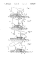
- FIG. 1 is an elevational view, partially in vertical and longitudinal cross-section, of a rear binding according to the invention whose body is engaged on the slide affixed to the ski before the final placement of the body of the binding in the desired longitudinal position;
- FIGS. 2 and 3 are views, similar to that of FIG. 1, of the heel binding in the course of its longitudinal displacement until its position of desired adjustment;
- FIG. 4 is a view, similar to that of FIG. 1, of the rear binding after immobilization of a shoe or boot on the ski;
- FIG. 5 is a rear view of the rear binding shown in FIGS. 1-4;
- FIG. 6 is perspective view of two safety bindings, namely, a front binding and a rear binding, mounted on a ski by means of a common slide;
- FIG. 7 is a partial vertical and transverse cross-sectional view illustrating the assembly of the latch of the front binding of FIG. 6;
- FIG. 8 is a perspective view of the latch of the front binding of FIG. 6;
- FIG. 9 is a vertical and longitudinal cross-sectional view, on a larger scale, of a portion of the slide comprising a plug engaged in a notch of the slide;
- FIG. 10 is a perspective view of the plug shown in FIG. 9;
- FIG. 11 is a vertical and longitudinal cross-sectional view of on embodiment of a plug engaged in a notch of the slide;
- FIG. 12 is a perspective view of the plug shown in FIG. 11;
- FIG. 13 is a vertical and transverse cross-sectional view, on a larger scale, of a marginal portion of the slide in the longitudinal edge of which are formed the notches containing the plugs;
- FIG. 14 is a perspective view of a plug shown in FIG. 13;
- FIGS. 15 and 16 illustrate one alternative embodiment of the invention.
- the present invention overcomes the disadvantages described above in connection with known bindings by providing a safety binding provided with means making it possible to considerably simplify the assembly and adjustment of the longitudinal position of the binding by automatically stopping the body of the binding, during the sliding of the body, in the longitudinal position corresponding exactly to the position which the shoe or boot must occupy on the ski, regardless of the length thereof.
- the safety binding of the present invention comprises a longitudinal slide affixed to the ski; a body carrying a retention jaw for one end of a shoe or boot before being mounted on the ski; an energization mechanism of the jaw; the body being longitudinally slidably mounted on the slide; means for immobilizing the body on the slide in one of a plurality of different longitudinal positions, the immobilization means comprising, on one of the two elements which constitute the body and the slide, a succession of longitudinally aligned notches, forming a track, respectively determining the different longitudinal positions that the body can occupy on the slide, and, on the other element, an elastically biased latch comprising, facing the succession of notches, at least one projection, the projection or projections of the latch being elastically biased in the direction of the notches in a manner so as to be able to be engaged in one of the notches and thus immobilize the body on the slide in the desired longitudinal position.
- the notches of the track which correspond to binding positions other than the desired position, are blocked by removable
- the safety binding according to the invention which is shown in particular with regard to FIGS. 1-5, is a heel binding 1 adapted to maintain the rear end of a shoe or boot 2 (FIG. 4) on ski 3.
- the heel binding 1 comprises a body 4 supporting, at its front portion, a retention jaw for boot 2 and contains an energization mechanism for the jaw.
- Body 4 is affixed, at its lower portion, to a base 5 on which body 4 can longitudinally slide.
- a longitudinal opening 6 is provided in which a compression spring 7 is located which constitutes a retraction or return spring.
- This compression spring 7 rests, at its front end, on a transverse surface 8 forming an abutment of body 4, and at its rear end, on a piston 9 slidably mounted within opening 6.
- Heel binding 1 furthermore comprises a slide 11 which is affixed to the horizontal upper surface of ski 3 by any appropriate means, for example, by screws.
- the slide 11 is constituted by a metallic plate which can be initially assembled with base 5 of body 4 of the binding or, alternatively, it can be affixed on the ski before the positioning of body 4 of the binding.
- base 5 and slide 11 are configured in a manner so as to be engaged with one another with a minimum of lateral play while nevertheless allowing for the longitudinal sliding of base 5 and, consequently, of body 4 with respect to slide 11 affixed to the ski.
- the slide 11 constitutes a platform which is affixed to a longitudinal upper projection 3a of ski 3, shown in the perspective view of FIG. 6, which has a transverse rectangular cross-section and whose width is thus less than that of ski 3.
- the platform which forms the slide 11 has itself a width greater than that of the projection 3a but less than that of ski 3 so that its two longitudinal edges 11a extend slightly beyond and are offset with respect to the two longitudinal edges of projection 3a, i.e., they do not extend to the sides 3b, 3c of ski 3.
- base 5 which slides on platform 11 forming the slide has a transverse cross-section in the shape of an inverted C.
- base 5 has a horizontal upper member 5a which ends, along its two longitudinal edges, in two short vertical and longitudinal wings 5b extending downwardly, themselves extended at their lower ends by two horizontal, or substantially horizontal, short wings 5c each extending in the direction of one another, i.e., towards the vertical and longitudinal plane of symmetry of the binding.
- the two wings 5b and 5c thus constitute a groove which tightly engages a longitudinal edge 11a of the platform forming slide 11.
- slide 11 has, at its central portion, a track constituted by a succession of notches 12 which are longitudinally aligned.
- These notches 12 can be holes, which extend through both sides of slide or cut-outs hollowed in only a portion of the thickness of the slide, as is shown in FIGS. 1-4.
- the notches 12 can have various shapes and, in particular, they can have, seen in a plan view, a rectangular shape which extend lengthwise in the transverse direction.
- a latch 13, which is pivotably mounted around a generally transverse axis on base 5 of heel binding, 1 cooperates with notches 12. This latch 13 carries, at its lower surface, at least one projection 14 adapted to engage in notches 12 of slide 11.
- the latch 13 carries two teeth or projections 14 which are transversely aligned, as can be seen in FIG. 5.
- the latch carries at least one succession of a plurality of longitudinally aligned teeth or projections.
- Latch 13 is elastically biased in a manner such that its one or more lower projections 14 is constantly biased downwardly.
- the elastic bias of latch 13 is ensured by the return spring 7 pushing piston 9 towards the rear, which piston is in contact with the end of a front arm 13a of latch 13. Latch 13 is thus constantly biased in the clockwise direction in the drawing.
- slide 11 is delivered, before assembly, with all of its notches 12 effectively blocked by plugs 15.
- plugs 15 has a shape and dimension such that it effectively entirely blocks the opening of notches 12 and that its upper surface is flush or substantially flush with the upper surface of platform 11 which forms a slide.
- the assembler desires to position and immobilize heel binding 1 in the longitudinal position desired, he removes the plug 15 which corresponds to the desired longitudinal position from its respective notch 12.
- any tool can be used which can be engaged in the notch and "pop" the plug 15 therefrom.
- the slide 11 is shown to have five successive notches 12, corresponding to five different longitudinal positions. It is likewise shown in FIG. 3 of the example that the heel binding 11 is affixed in the median longitudinal position and, consequently, the assembler first had to remove plug 15 which had been located in the median notch 12, as is illustrated in FIG. 1.
- the assembler slides, with a single hand, body 4 of the binding on slide 11, from left to right.
- the latch remains permanently raised because projection 14 of latch 13 slides on the upper surface of slide 11 and it passes without difficulty over the first two notches 12, positioned to the left of the median notch, which are blocked by their respective plugs 15, as is illustrated in FIG. 2.
- projection 14 of latch 13 can engage in notch 12, as a result of the rocking movement of latch 13 in the clockwise direction, under the effect of return spring 8.
- binding 1 is locked in the desired longitudinal position as is shown in FIG. 3.
- the latch 13 is thus immobilized and it constitutes, through its lower arm 13a, a rear abutment for piston 9.
- Body 4 of heel binding 1 can, however, slide freely with respect to base 5, during insertion of the shoe or boot 2 as is shown in FIG. 4, the return spring 9 being thus further compressed.
- latch 13 comprises, at the rear of projection 14, a rear arm 13b extending upwardly whose end is accessible from the rear of heel binding 1. It is consequently possible to lift rear arm 13b by means of an appropriate tool engaged between the rear arm 13b of latch 13 and base 5 and, consequently, to rock the assembly of the latch 13 in the counterclockwise direction, which serves to disengage projection 14 from its notch 12 and to make it possible to again longitudinally slide heel binding 1, to allow for the adjustment of its longitudinal position.
- FIG. 6 illustrates two safety bindings mounted on a common slide 11 affixed to ski 3, namely, the heel binding 1 previously described, and a front binding 16.
- the front binding 16 of any known type, is affixed to base 17, which is similar to base 5 of heel binding 1.
- Bases 5 and 17 of heel binding and of front binding 16 are respectively slidably engaged on two portions, rear portion 11b and front 11c of common slide 11, which are connected to one another by a central portion 11d of a smaller width.
- the central portion 11d is adapted to allow for engagement of the bindings and 16 first by a movement which is perpendicular, or substantially perpendicular, to the ski (arrow f), then by a longitudinal movement towards the rear for the heel binding 1 (arrow fl) and towards the front for the front abutment 16 (arrow f2).
- the width of the central portion 11d is selected, for this purpose, to be less than the width of the opening defined between the two short horizontal wings constituting the ends of the C-shaped cross-section of the two bases 5 and 17.
- the adjustment and longitudinal position of front binding 16 is achieved by means of a succession of notches 18 which are provided in a longitudinal edge 11a of the front portion 11c of slide 11. These notches are constituted by vertical or substantially vertical cut-outs opening onto the edge 11a and they are filled by plugs 19 whose upper surfaces are flush or substantially flush with the upper surface of the front portion 11c.
- Latch 21 is pivotal on base 17 of front binding 16 around a longitudinal axis 22 and it is biased downwardly by a spring 23.
- Latch 21 supports, on its inner surface, a projection 24 which is adapted to become engaged in one of the lateral notches 18.
- Latch 21 likewise comprises an external arm 21a making it possible to lift the latch from the exterior by means of an appropriate tool such as a screwdriver.
- the longitudinal position desired for front binding 16 is predetermined by removing a plug 19 from its respective lateral notch 18.
- the lateral notches 18 are five in number and that the desired longitudinal position corresponding to the engagement of projection 24 of latch 21 in notch 12 is positioned immediately after the frontwardmost notch.
- FIGS. 9 and 10 illustrate, on a larger scale, an embodiment of a plug 15 adapted to be engaged in notches 12 defining the longitudinal positions of heel binding 1, these notches being constituted by parallelpipedic cut-outs formed in the upper surface of slide 11.
- Each plug 15 has a substantially T-shape whose upper head 15a, of parallelpipedic shape, has a length which is somewhat less than the length of notch 12, in the transverse direction, in which it is lodged.
- a frontal surface 15b of this head 15a defines, with a frontal surface facing notch 12, a space in which the end of the tool 25, such a screwdriver, can be engaged and which can be utilized as a lever to eject plug 15 from its notch 12.
- Head 15a of plug 15 is extended, at its lower portion, by a nipple 15c which engages in a lower corresponding aperture 12a extending from notch 12 downwardly, to ensure the maintenance of plug 15 in position.
- head 15a of plug 15 has between its frontal surface 15b, defining the opening for the introduction of tool 25, and its lower surface, a bevelled surface 15d which facilitates the penetration of the point of tool 25.
- the notch 12 is bored on both sides in slide 11 and it defines a parallelpipedic volume.
- a plug 27 is engaged which has a substantially parallelpipedic shape and a thickness which is equal to or substantially equal to the depth of notch 12 and a width which is equal to or substantially equal to the width of the notch.
- its length is less than the length of notch 12 so as to define, between one of its frontal surfaces 27a and the frontal surface facing notch 12, a space in which the end portion of tool 25 can be engaged to "pop" plug 27 out of notch 12.
- the frontal surface 27a preferably has, at its lower portion, a bevelled surface 27b which facilitates the penetration of the tip of tool 25.
- the plug which is engaged in a lateral notch 18 is constituted by a parallelpipedic block, whose height is equal to or substantially equal to the thickness of slide 11. Furthermore, the width of plug 19 is equal to or substantially equal to that of notch 18 in which it is thus maintained tightly by a friction fit.
- notches 12 and 18 and the corresponding plugs 15, 19, 27 preferably have a parallelpipedic shape, this shape is not limiting and other shapes can be utilized such as, e.g., prismatic or cylindrical shapes, in particular.
- FIGS. 15 and 16 illustrate another embodiment according to which the method of adjustment by plugs previously described is combined with a conventional length adjustment.
- Binding 1 is mounted on base 5' by means of a slide 30, the binding 1 being slidable in a longitudinal direction along the length of this slide.
- Slide 30 is affixed integrally with base 5'.
- binding 1 along slide 30 is controlled by means which make it possible to adjust the initial position of the binding on its slide.
- These means are illustrated as a micrometric screw 31, whose head is retained by an upstanding lug 32 affixed to the slide, and whose threaded portion is engaged in a tapped orifice (not visible) of the body of binding 1. This construction is known of one of ordinary skill in the art.
- Base 5' itself is similar to base 5 described in connection to FIG. 6, and it cooperates with slide 11 of ski 3. As in the preceding case, slide 11 has a series of notches 12 which are blocked by plugs 15.
- FIG. 15 shows a plug 35 which has been removed from its notch 36.
- base 5' has, in its front portion, a latch 33 which carries a tooth 34 which is adapted to engage in the notch whose plug has been removed, i.e., the notch 36.
- the latch 33 is, for example, constituted by a flexible blade 38 which is mounted within a longitudinal slot 39 of base 5', flush or substantially flush with the upper surface base 5'. Blade 38 is connected to the base preferably at its rear portion. Furthermore, it is elastically prestressed in a manner such that tooth 34 projects toward the lower surface of the base, as is seen in FIG. 16.
- binding 1 on ski 3 occurs in the following manner. Depending upon the size of the boot of the skier, the assembler determines which plug 15 must be removed (for example, plug 35), and he removes it in a manner previously described. He engages base 5' on slide 11 and slides the binding until tooth 34 of latch 33 falls in the unblocked notch 33. This constitutes a "rough" positioning of the binding. A more precise adjustment of the longitudinal position is achieved by turning the screw 31. Thus, notches 15 make it possible to achieve a rough adjustment, for example, for different size ranges of shoes or boots, fine adjustment then being achieved by other length adjustment means which are particular to the binding.
- the assembler disengages latch 33 from notch 36 and then extracts the plug 12 corresponding to the new longitudinal position desired. If desired, he "re-blocks" the first notch 36 by means of a plug 12.
Landscapes
- Chemical & Material Sciences (AREA)
- Health & Medical Sciences (AREA)
- Chemical Kinetics & Catalysis (AREA)
- Medicinal Chemistry (AREA)
- Polymers & Plastics (AREA)
- Organic Chemistry (AREA)
- Footwear And Its Accessory, Manufacturing Method And Apparatuses (AREA)
- Fittings On The Vehicle Exterior For Carrying Loads, And Devices For Holding Or Mounting Articles (AREA)
- Silicon Polymers (AREA)
Applications Claiming Priority (2)
| Application Number | Priority Date | Filing Date | Title |
|---|---|---|---|
| FR8810955 | 1988-08-17 | ||
| FR8810955A FR2635465B1 (fr) | 1988-08-17 | 1988-08-17 | Fixation de securite pour ski |
Publications (1)
| Publication Number | Publication Date |
|---|---|
| US5056809A true US5056809A (en) | 1991-10-15 |
Family
ID=9369367
Family Applications (1)
| Application Number | Title | Priority Date | Filing Date |
|---|---|---|---|
| US07/394,721 Expired - Fee Related US5056809A (en) | 1988-08-17 | 1989-08-16 | Safety ski binding |
Country Status (6)
| Country | Link |
|---|---|
| US (1) | US5056809A (de) |
| JP (1) | JPH02107278A (de) |
| KR (1) | KR900003247A (de) |
| AT (1) | ATA186589A (de) |
| DE (1) | DE3924899A1 (de) |
| FR (1) | FR2635465B1 (de) |
Cited By (11)
| Publication number | Priority date | Publication date | Assignee | Title |
|---|---|---|---|---|
| US5575496A (en) * | 1994-01-28 | 1996-11-19 | Atomic Austria Gmbh | Coupling device between a boot and a piece of sports apparatus such as a ski binding |
| US5690352A (en) * | 1995-02-02 | 1997-11-25 | Htm Sport- Und Freizeitgeraete Aktiengesellschaft | Snowboard binding |
| US5732968A (en) * | 1994-05-09 | 1998-03-31 | Htm Sport- Und Freizeitgeraete Aktiengesellschaft | Apparatus for the longitudinal adjustment |
| US5738364A (en) * | 1994-05-30 | 1998-04-14 | Htm Sport- Und Freizeitgeraete Aktiengesellschaft | Ski binding |
| WO2002049728A1 (en) * | 2000-12-19 | 2002-06-27 | Elan, D.D. | Ski or similar skating requisite with incorporated assembly for adjustable attaching a ski binding |
| EP1611927A1 (de) * | 2004-07-02 | 2006-01-04 | Völkl Sports GmbH & Co. KG | Schneegleitbrett |
| US20060232045A1 (en) * | 2005-04-15 | 2006-10-19 | Salomon S.A. | Interface device between a gliding board and a boot biding element |
| US20070138766A1 (en) * | 2005-12-20 | 2007-06-21 | Salomon S.A. | Device for receiving a foot or boot on a sports apparatus |
| EP1938871A1 (de) * | 2006-12-28 | 2008-07-02 | Skis Rossignol | Automatische Befestigung einer Fixierungsvorrichtung für Schuhe auf einem Snowboard |
| US20100109290A1 (en) * | 2008-11-03 | 2010-05-06 | Atomic Austria Gmbh | Ski binding with a positioning and fixing mechanism for its binding piece bodies |
| US10967243B2 (en) * | 2016-06-23 | 2021-04-06 | Fischer Sports Gmbh | Ski binding |
Families Citing this family (7)
| Publication number | Priority date | Publication date | Assignee | Title |
|---|---|---|---|---|
| DE3929352A1 (de) * | 1989-09-04 | 1991-03-14 | Witco As | Seitliche fuehrungsvorrichtung eines skischuhs |
| DE29520845U1 (de) * | 1995-03-03 | 1996-04-18 | Marker Deutschland Gmbh | Vorrichtung zur Längsverstellung eines Skibindungsteiles |
| AT408725B (de) * | 1999-09-21 | 2002-02-25 | Atomic Austria Gmbh | Bindungshaltesystem zur schnellmontage eines vorder- und fersenbackens einer schibindung |
| FR2820335B1 (fr) * | 2001-02-02 | 2003-03-07 | Rossignol Sa | Plaque interface destinee a etre solidarisee a la face superieure d'un ski |
| DE10254471A1 (de) † | 2002-11-21 | 2004-06-03 | Madsus A/S | Ski mit Bindungs-Montagehilfe, Verfahren zur Herstellung eines solchen Ski sowie entsprechende Montagehilfe |
| DE102006034869A1 (de) * | 2006-06-30 | 2008-01-03 | Marker Völkl International GmbH | Schneegleitbrett, insbesondere Ski |
| EP3202470B1 (de) | 2014-03-19 | 2018-05-09 | Madshus AS | Mechanismus zur längsverriegelung einer skibindung auf einer montageplatte |
Citations (14)
| Publication number | Priority date | Publication date | Assignee | Title |
|---|---|---|---|---|
| FR1464104A (fr) * | 1965-11-18 | 1966-07-22 | Fixation de ski | |
| CH469492A (fr) * | 1967-12-04 | 1969-03-15 | Reuge Sa | Dispositif de fixation de ski comprenant une butée de sécurité avant et/ou une butée de sécurité arrière réglable en position axiale sur le ski |
| US3785666A (en) * | 1971-02-05 | 1974-01-15 | G Pierre | Device for changing the longitudinal position of a ski binding |
| US3960384A (en) * | 1974-03-08 | 1976-06-01 | Etablissements Francois Salomon Et Fils | Method for providing recoil in a safety binding for skis and device for the same |
| DE2617395A1 (de) * | 1976-04-21 | 1977-11-10 | Franke Rainer | Vorrichtung fuer eine in skilaengsrichtung verstellbare bindung |
| FR2380795A1 (fr) * | 1977-02-18 | 1978-09-15 | Kautzky Norbert | Dispositif d'assemblage pour la fixation separable d'une attache a des skis |
| US4157193A (en) * | 1976-11-02 | 1979-06-05 | Beyl Jean Joseph Alfred | Ski binding device |
| FR2454822A1 (fr) * | 1979-04-26 | 1980-11-21 | Salomon & Fils F | Fixation de securite pour ski |
| EP0084324A1 (de) * | 1982-01-18 | 1983-07-27 | Ess GmbH Skibindungen | Längsverstelleinrichtung für eine Skibindung |
| US4524990A (en) * | 1980-11-14 | 1985-06-25 | Tmc Corporation | Adjusting mechanism |
| US4681339A (en) * | 1984-04-27 | 1987-07-21 | Tmc Corporation | Ski binding part, in particular a front jaw |
| US4747613A (en) * | 1986-03-14 | 1988-05-31 | Salomon S.A. | Ski manufactured to have pre-bored screw holes for the mounting of bindings |
| FR2614545A1 (fr) * | 1987-04-30 | 1988-11-04 | Salomon Sa | Fixation de securite pour ski |
| WO1989007475A2 (en) * | 1988-02-19 | 1989-08-24 | Tmc Corporation | Ski binding |
-
1988
- 1988-08-17 FR FR8810955A patent/FR2635465B1/fr not_active Expired - Fee Related
-
1989
- 1989-07-27 DE DE3924899A patent/DE3924899A1/de not_active Withdrawn
- 1989-08-01 AT AT0186589A patent/ATA186589A/de not_active Application Discontinuation
- 1989-08-11 JP JP1207098A patent/JPH02107278A/ja active Pending
- 1989-08-16 KR KR1019890011664A patent/KR900003247A/ko not_active Application Discontinuation
- 1989-08-16 US US07/394,721 patent/US5056809A/en not_active Expired - Fee Related
Patent Citations (16)
| Publication number | Priority date | Publication date | Assignee | Title |
|---|---|---|---|---|
| FR1464104A (fr) * | 1965-11-18 | 1966-07-22 | Fixation de ski | |
| CH469492A (fr) * | 1967-12-04 | 1969-03-15 | Reuge Sa | Dispositif de fixation de ski comprenant une butée de sécurité avant et/ou une butée de sécurité arrière réglable en position axiale sur le ski |
| US3785666A (en) * | 1971-02-05 | 1974-01-15 | G Pierre | Device for changing the longitudinal position of a ski binding |
| US3960384A (en) * | 1974-03-08 | 1976-06-01 | Etablissements Francois Salomon Et Fils | Method for providing recoil in a safety binding for skis and device for the same |
| DE2617395A1 (de) * | 1976-04-21 | 1977-11-10 | Franke Rainer | Vorrichtung fuer eine in skilaengsrichtung verstellbare bindung |
| US4157193A (en) * | 1976-11-02 | 1979-06-05 | Beyl Jean Joseph Alfred | Ski binding device |
| FR2380795A1 (fr) * | 1977-02-18 | 1978-09-15 | Kautzky Norbert | Dispositif d'assemblage pour la fixation separable d'une attache a des skis |
| US4188044A (en) * | 1977-02-18 | 1980-02-12 | Norbert Kautzky | Connecting arrangement for the detachable mounting of a binding on skis |
| FR2454822A1 (fr) * | 1979-04-26 | 1980-11-21 | Salomon & Fils F | Fixation de securite pour ski |
| US4524990A (en) * | 1980-11-14 | 1985-06-25 | Tmc Corporation | Adjusting mechanism |
| EP0084324A1 (de) * | 1982-01-18 | 1983-07-27 | Ess GmbH Skibindungen | Längsverstelleinrichtung für eine Skibindung |
| US4522424A (en) * | 1982-01-18 | 1985-06-11 | Ess Gmbh Skibindungen | Ski binding clamp |
| US4681339A (en) * | 1984-04-27 | 1987-07-21 | Tmc Corporation | Ski binding part, in particular a front jaw |
| US4747613A (en) * | 1986-03-14 | 1988-05-31 | Salomon S.A. | Ski manufactured to have pre-bored screw holes for the mounting of bindings |
| FR2614545A1 (fr) * | 1987-04-30 | 1988-11-04 | Salomon Sa | Fixation de securite pour ski |
| WO1989007475A2 (en) * | 1988-02-19 | 1989-08-24 | Tmc Corporation | Ski binding |
Cited By (13)
| Publication number | Priority date | Publication date | Assignee | Title |
|---|---|---|---|---|
| US5575496A (en) * | 1994-01-28 | 1996-11-19 | Atomic Austria Gmbh | Coupling device between a boot and a piece of sports apparatus such as a ski binding |
| US5732968A (en) * | 1994-05-09 | 1998-03-31 | Htm Sport- Und Freizeitgeraete Aktiengesellschaft | Apparatus for the longitudinal adjustment |
| US5738364A (en) * | 1994-05-30 | 1998-04-14 | Htm Sport- Und Freizeitgeraete Aktiengesellschaft | Ski binding |
| US5690352A (en) * | 1995-02-02 | 1997-11-25 | Htm Sport- Und Freizeitgeraete Aktiengesellschaft | Snowboard binding |
| WO2002049728A1 (en) * | 2000-12-19 | 2002-06-27 | Elan, D.D. | Ski or similar skating requisite with incorporated assembly for adjustable attaching a ski binding |
| EP1611927A1 (de) * | 2004-07-02 | 2006-01-04 | Völkl Sports GmbH & Co. KG | Schneegleitbrett |
| US20060232045A1 (en) * | 2005-04-15 | 2006-10-19 | Salomon S.A. | Interface device between a gliding board and a boot biding element |
| US20070138766A1 (en) * | 2005-12-20 | 2007-06-21 | Salomon S.A. | Device for receiving a foot or boot on a sports apparatus |
| EP1938871A1 (de) * | 2006-12-28 | 2008-07-02 | Skis Rossignol | Automatische Befestigung einer Fixierungsvorrichtung für Schuhe auf einem Snowboard |
| FR2910821A1 (fr) * | 2006-12-28 | 2008-07-04 | Rossignol Sa | Fixation automatique sur une planche de glisse d'un dispositif de fixation de chaussure |
| US20100109290A1 (en) * | 2008-11-03 | 2010-05-06 | Atomic Austria Gmbh | Ski binding with a positioning and fixing mechanism for its binding piece bodies |
| US7988180B2 (en) * | 2008-11-03 | 2011-08-02 | Atomic Austria Gmbh | Ski binding with a positioning and fixing mechanism for its binding piece bodies |
| US10967243B2 (en) * | 2016-06-23 | 2021-04-06 | Fischer Sports Gmbh | Ski binding |
Also Published As
| Publication number | Publication date |
|---|---|
| DE3924899A1 (de) | 1990-02-22 |
| FR2635465A1 (fr) | 1990-02-23 |
| FR2635465B1 (fr) | 1990-11-16 |
| ATA186589A (de) | 1995-03-15 |
| KR900003247A (ko) | 1990-03-26 |
| JPH02107278A (ja) | 1990-04-19 |
Similar Documents
| Publication | Publication Date | Title |
|---|---|---|
| US5056809A (en) | Safety ski binding | |
| US4082312A (en) | Cross country ski binding | |
| US5116073A (en) | Safety ski binding | |
| US7744113B2 (en) | Restraining and longitudinal position adjusting device of a binding for skis | |
| US4955633A (en) | Adjusting device for a ski binding | |
| EP0163054A1 (de) | Kombination von Skibindung und Skischuh | |
| US5348335A (en) | Device for adjustment of the longitudinal position of an alpine binding | |
| US4586727A (en) | Variable-height device for supporting a boot on a ski | |
| US5114172A (en) | Integral binding | |
| EP0131234A2 (de) | Skibindung, besonders Langlaufskibindung | |
| US4310170A (en) | Cross-country ski binding | |
| US4524990A (en) | Adjusting mechanism | |
| US4008908A (en) | Snow ski binding | |
| US4768805A (en) | Meta binding | |
| US4997199A (en) | Foot plate for a ski binding | |
| US4061357A (en) | Ski binding having a releasable boot plate provided with a ski brake | |
| US6073955A (en) | Alpine ski binding element equipped with a detachable brake | |
| JPH02200283A (ja) | アルペンスキー用の踵締め具 | |
| US4600214A (en) | Ski boot locating apparatus | |
| US4690423A (en) | Ski braking device | |
| US4230337A (en) | Ski bindings and ski brakes associated therewith | |
| US4160556A (en) | Heel or sole holder for a sole plate of a safety ski binding and sole plate equipped with such holder | |
| US4915407A (en) | Binding with independently acting release and retention features | |
| US5044655A (en) | Ski binding for a cross-country or touring ski | |
| US4986562A (en) | Ski binding |
Legal Events
| Date | Code | Title | Description |
|---|---|---|---|
| AS | Assignment |
Owner name: SALOMON S.A., FRANCE Free format text: ASSIGNMENT OF ASSIGNORS INTEREST.;ASSIGNORS:BRISCHOUX, JEAN-CLAUDE;RENAUD-GOUD, GILLES;REEL/FRAME:005184/0997 Effective date: 19891103 |
|
| REMI | Maintenance fee reminder mailed | ||
| LAPS | Lapse for failure to pay maintenance fees | ||
| FP | Lapsed due to failure to pay maintenance fee |
Effective date: 19951018 |
|
| STCH | Information on status: patent discontinuation |
Free format text: PATENT EXPIRED DUE TO NONPAYMENT OF MAINTENANCE FEES UNDER 37 CFR 1.362 |