US5050974A - Optical system for endoscopes - Google Patents
Optical system for endoscopes Download PDFInfo
- Publication number
- US5050974A US5050974A US07/406,383 US40638389A US5050974A US 5050974 A US5050974 A US 5050974A US 40638389 A US40638389 A US 40638389A US 5050974 A US5050974 A US 5050974A
- Authority
- US
- United States
- Prior art keywords
- sub
- optical system
- lens component
- endoscopes
- reference symbol
- Prior art date
- Legal status (The legal status is an assumption and is not a legal conclusion. Google has not performed a legal analysis and makes no representation as to the accuracy of the status listed.)
- Expired - Lifetime
Links
Images

Classifications
-
- A—HUMAN NECESSITIES
- A61—MEDICAL OR VETERINARY SCIENCE; HYGIENE
- A61B—DIAGNOSIS; SURGERY; IDENTIFICATION
- A61B1/00—Instruments for performing medical examinations of the interior of cavities or tubes of the body by visual or photographical inspection, e.g. endoscopes; Illuminating arrangements therefor
- A61B1/04—Instruments for performing medical examinations of the interior of cavities or tubes of the body by visual or photographical inspection, e.g. endoscopes; Illuminating arrangements therefor combined with photographic or television appliances
-
- B—PERFORMING OPERATIONS; TRANSPORTING
- B29—WORKING OF PLASTICS; WORKING OF SUBSTANCES IN A PLASTIC STATE IN GENERAL
- B29D—PRODUCING PARTICULAR ARTICLES FROM PLASTICS OR FROM SUBSTANCES IN A PLASTIC STATE
- B29D11/00—Producing optical elements, e.g. lenses or prisms
-
- G—PHYSICS
- G02—OPTICS
- G02B—OPTICAL ELEMENTS, SYSTEMS OR APPARATUS
- G02B17/00—Systems with reflecting surfaces, with or without refracting elements
-
- G—PHYSICS
- G02—OPTICS
- G02B—OPTICAL ELEMENTS, SYSTEMS OR APPARATUS
- G02B21/00—Microscopes
- G02B21/02—Objectives
-
- G—PHYSICS
- G02—OPTICS
- G02B—OPTICAL ELEMENTS, SYSTEMS OR APPARATUS
- G02B23/00—Telescopes, e.g. binoculars; Periscopes; Instruments for viewing the inside of hollow bodies; Viewfinders; Optical aiming or sighting devices
- G02B23/24—Instruments or systems for viewing the inside of hollow bodies, e.g. fibrescopes
- G02B23/26—Instruments or systems for viewing the inside of hollow bodies, e.g. fibrescopes using light guides
-
- G—PHYSICS
- G02—OPTICS
- G02B—OPTICAL ELEMENTS, SYSTEMS OR APPARATUS
- G02B9/00—Optical objectives characterised both by the number of the components and their arrangements according to their sign, i.e. + or -
- G02B9/60—Optical objectives characterised both by the number of the components and their arrangements according to their sign, i.e. + or - having five components only
-
- G—PHYSICS
- G02—OPTICS
- G02B—OPTICAL ELEMENTS, SYSTEMS OR APPARATUS
- G02B9/00—Optical objectives characterised both by the number of the components and their arrangements according to their sign, i.e. + or -
- G02B9/62—Optical objectives characterised both by the number of the components and their arrangements according to their sign, i.e. + or - having six components only
Definitions
- the present invention relates to an imaging optical system for endoscopes.
- Fiberscopes using image guide fiber bundles are practically employed in a large number as endoscopes.
- video endoscopes using various types of solid-state image pickup devices in place of the image guides are also used in a large number.
- the video color imaging systems are classified roughly into the field sequential color system and the dot sequential color systems.
- the latter has a composition comprising a color encoding filter which is composed of mini-size color filters integrated in mosaic patterns corresponding to the picture elements of a solid-state image pickup device (usually referred to as the color mosaic filter).
- the color mosaic filter When a wide space is reserved between the filter and the light-receiving surface of the solid-state image pickup device, however, the light incident on the solid-stage image pickup device does not fall on the picture element on which the light is originally to fall after passing through the color encoding filter but on the neighboring picture element, thereby producing color ununiformity on an image (hereinafter referred to as the color shading).
- a primary object of the present invention is to provide an imaging optical system for endoscopes capable of forming an image free from the color shading even when the solid-state image pickup devices comprising the mosaic filters are used.
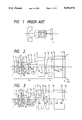
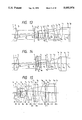
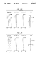
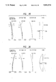
- the optical system for endoscopes according to the present invention has the fundamental composition illustrated in FIG. 2 wherein a field lens component L F is arranged on the image side of an imaging lens system L M comprising an aperture stop S and a solid-state image pickup device is arranged on the side where rays emerge from said field lens component L F . Further, the optical system for endoscopes according to the present invention is so designed as to satisfy the following condition (1):
- reference symbol f F represents focal length of the field lens component L F and the reference symbol f designates focal length of the optical system as a whole.
- the optical system according to the present invention is so adapted as to allow the principal ray to be incident nearly perpendicularly on the image surface thereof and therefore capable of preventing the color shading from being produced.
- the optical system will have too long a total length and too large an outside diameter, thereby being unsuited for use with endoscopes.
- the optical system for endoscopes comprises the field lens component L F arranged on the image side of the imaging lens system L M comprising the aperture stop and is so designed as to satisfy the condition (1). It is desirable to use, as at least one of the surfaces of the field lens component or in the vicinity thereof, an aspherical surface including portions whose refractive functions are gradually weakened as the portions are farther from the optical axis toward the margin.
- the optical system according to the present invention is so adapted as to prevent the color shading by arranging the field lens component L F on the image side of the imaging lens system L M so that the principal ray is incident perpendicularly on the image surface thereof.
- the field lens component L F on the image side of the imaging lens system L M so that the principal ray is incident perpendicularly on the image surface thereof.
- an aspherical surface at a location where spherical aberration is produced remarkably when tracing is made in the reverse direction from the image side, i.e., at a location in the vicinity of the field lens component L F .
- An optical system for endoscopes is generally designed as the retrofocus type consists of a front lens unit which has negative refractive power as a whole and is arranged on the object side of an aperture stop, and a rear lens unit which has positive refractive power as a whole and is arranged on the image side of the aperture stop.
- a positive lens component produces negative spherical aberration since it refracts rays more largely as the portions thereof become farther from the optical axis.
- the aspherical surface is arranged in the vicinity of the field lens component L F so as to include portions whose refractive functions are gradually weakened as they are farther from the optical axis toward the margin.
- the weakening of refractive function of a positive lens component means weakening of the converging function, i.e., the positive power thereof, whereas weakening of refractive function of a negative lens component means weakening of the diverging function, i.e., the negative power thereof.
- the optical system for endoscopes according to the present invention has a large field angle of approximately 100° or wider, barrel-shaped distortion is produced remarkably as image height increases.
- an aspherical surface In order to correct distortion, it is sufficient to arrange an aspherical surface at a location at which the principal ray is high.
- a shape For the above-described aspherical surface to be arranged in the vicinity of the field lens component L F in the optical system for endoscopes according to the present invention, however, a shape must be selected in such a manner that the rays at all the image heights are incident on an image pickup device at a definite angle (perpendicularly). It is therefore desirable to correct distortion by arranging the aspherical surface at a location at which rays are high on the object side of the aperture stop.
- the aspherical surface to be arranged for correcting distortion should include such portions as to gradually weaken the refractive function of the lens component as the portions are farther from the optical axis toward the margin.
- the lens component which is located on the object side of the aperture stop and at which ray is the highest is the first lens component, and this lens component is usually designed as a negative lens component in an optical system for endoscopes.
- Remarkable distortion is produced by the object side surface of the first lens component (the first surface of the optical system) since said surface refracts rays outward more largely as the surface portions are farther from the optical axis toward the margin.
- the first surface is designed as an aspherical surface including portions which weaken the refractive function of the lens component as the portions are farther from the optical axis toward the margin, for example, it is possible to correct distortion owing to the fact that the aspherical surface moderates refraction of the rays.
- reference symbol D 1 represents the optical path length to be reserved between the aperture stop S and the field lens component L F .
- the solid-state image pickup device has sensitivity for the light having infrared wavelength and degrades color reproducibility on an image.
- an optical filter such as an infrared cut filter or the similar member in the optical path of the optical system.
- the condition (2) is required for arranging the optical member such as an optical filter.
- D 1 should desirably satisfy the condition (2). If the condition (2) is not satisfied, it will be difficult to arrange an optical filter in the optical system for endoscopes according to the present invention.
- reference symbol D 2 represents optical path length as measured from the field lens component L F to the imaging surface, which should be measured from the vertex of the object side surface of the field lens component L F to the imaging surface when the field lens component L F is integrated with an image pickup device, or from the vertex of the image side surface of the field lens component L F to the imaging surface when the field lens component L F is separate from an image pickup device.
- D 2 has too small a value, it will be impossible to reserve a space for arranging, for example, an optical low pass filter for correcting moire. If D 2 has too large a value, in contrast, it will be possible to reserve a space sufficient for arranging the optical low pass filter or the similar member, but the optical system will have too long a total length and cannot be compact.
- the optical system is divided into a front subsystem located on the object side of the plane parallel plate and a rear subsystem located on the image side of the plane parallel plate.
- the optical system is to be divided into the front subsystem and the rear subsystem taking the plane parallel plate closest to the field lens component L F as a boundary.
- the front subsystem may be composed of a plural number of lens components including positive lens component(s) and negative lens component(s) for correcting aberrations.
- the reference symbol f 1 represents focal length of the front subsystem
- the reference symbol f n designates focal length of the negative lens components (not including the negative lens elements of the cemented doublets)
- the reference symbol f p denote total focal length of the lens elements not including the negative lens element(s) arranged in the front subsystem.
- the condition (4) defines focal length of the front subsystem. As f 1 becomes shorter, the optical path length is shorter between the front subsystem and the rear subsystem. If the condition (4) is not satisfied, it will therefore be impossible to arrange an optical filter.
- f n or f p exceeds the upper limit of the condition (5) or condition (6), the optical system will have too long a total length and too large an outside diameter, thereby making the optical system unsuited for use with endoscopes. If f p has a value smaller than the lower limit of the condition (6), in contrast, there will be available no space for arranging an optical filter.
- FIG. 1 shows a sectional view illustrating the conventional optical system for endoscopes
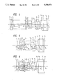
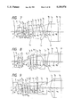
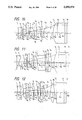
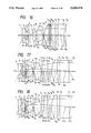
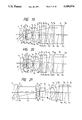
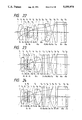
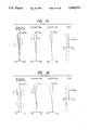
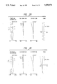
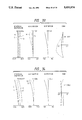
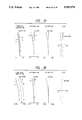
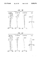
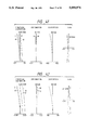
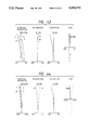
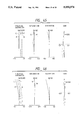
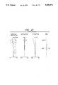
- FIG. 2 through FIG. 24 show sectional views illustrating Embodiments 1 through 23 of the optical system for endoscopes according to the present invention
- FIG. 25 through FIG. 47 show curves illustrating aberration characteristics of the Embodiments 1 through 23 of the present invention.
- the reference symbols r 1 , r 2 , . . . represent radii of curvature on the surfaces of the respective lens elements
- the reference symbols d 1 , d 2 , . . . designate thicknesses of the respective lens elements and airspaces reserved therebetween
- the reference symbols n 1 , n 2 , . . . denote refractive indices of the respective lens elements
- the reference symbols ⁇ 1 , ⁇ 2 , ... represent Abbe's numbers of the respective lens elements.
- the shapes of the aspherical surfaces used in Embodiments 16 through 23 are expressed by the following formula: ##EQU1## wherein the reference symbol r represents radius of curvature at the vertex of the aspherical surface, the reference symbols p designate the conic constant and the reference symbols B,E,F,G, . . . denote the coefficients of aspherical surface.
- a positive lens component on the object side of the aperture stop as illustrated, for example, in FIG. 2 out of the drawings showing the Embodiments.
- the optical system is asymmetrical.
- the rear subsystems comprise nearly afocal sections.
- the nearly afocal sections in the rear subsystems mean sections in which the principal ray is incident nearly in parallel with the optical axis and emerges nearly in parallel with the optical axis.
- the principal ray is nearly in parallel (approximately 15°) with the optical axis between the lens component L A and the lens component L B , and the principal ray is again in parallel with the optical axis after it emerges from the field lens component L F .
- the nearly afocal optical system in the Embodiment 6 is the section composed of the lens component L B and the field lens component L F .
- Embodiment 6 in which the principal ray has an inclination angle of 4° or smaller on the image surface and is nearly parallel with the optical axis, comprises a section in which the principal ray has an inclination angle of 18° or smaller, i.e., a nearly afocal section.
- an interference filter such as an infrared cut filter
- color shading cannot be produced on the screen since angles of incidence of rays incident on the interference filter vary little.
- Embodiments 6 through 13 are so designed as to satisfy the following condition (7):
- reference symbols f ap and f an represent focal lengths of the lens component having positive power and the lens component having negative power respectively in the nearly afocal optical section.
- the condition (7) defines the value which is generally referred to as the afocal ratio.
- the afocal ratio When this value becomes close to 0, the rays incident on the rear subsystem have larger angles of incidence, and angles of incidence are larger on the filter arranged between the front subsystem and the rear subsystem. Accordingly, it is permissible to arrange a filter whose characteristic is easily changed depending on variation of angles of incidence. It is desirable for the above-mentioned afocal ratio to have a large absolute value since such a value lowers heights of rays incident on the rear subsystem, thereby making it possible to reduce diameter of the optical system. When the afocal ratio has a value closer to 0 than -0.1, however, the optical system has a large diameter and cannot be set in the distal ends of endoscopes.
- Embodiments 3, 4 and 5 wherein the field lens component L F is integrated with an image pickup device enable to shorten total length of the optical system.
- the Embodiments 3, 12 and 13 are optical systems usable also for side viewing or oblique viewing. For such a purpose, it is sufficient to use a field direction changing prism such as a roof prism in place of the plane parallel plate arranged on the object side of the aperture stop. Out of these Embodiments, the Embodiments 12 and 13 are optical systems comprising nearly afocal sections in the rear subsystems thereof.
- the Embodiment 6 is a forward viewing optical system wherein the rear subsystem is designed as a nearly afocal optical system.
- the Embodiment 7 is an optical system comprising a smaller number of lens elements and so adapted as to reserve a wider airspace between the aperture stop and the convex lens component arranged on the image side thereof so that the rays are nearly in parallel with the optical axis.
- the convex lens component arranged on the object side of the aperture stop is designed as a cemented doublet for correcting lateral chromatic aberration.
- the convex lens component arranged on the image side of the aperture stop is designed as a cemented doublet for correcting coma.
- the concave lens component arranged in the rear subsystem is designed as a cemented doublet for enhancing workability of the concave lens component.
- the Embodiment 11 is characterized in that the filter is divided into two, the object side filter is designed as an absorption filter and the image side filter is designed as an interference filter for shortening total length of the optical system, and that a focus adjusting space is reserved between the field lens component and the filter arranged on the image side thereof for minimizing variation of field angle to be caused by focusing.
- the Embodiment 14 has the composition illustrated in FIG. 15 which is similar to the composition of the Embodiment 1 but is different in arrangement of the filter from the Embodiment 1.
- An optical system for medical endoscopes may comprise a YAG cut filter for carrying out medical treatment with YAG laser, etc. Since this filter has high reflectance for visible rays, it may produce, depending on the location thereof, ghost and/or flare by reflecting the rays which are reflected from an image pickup device.
- the filter When the filter is arranged on the image side of the field lens component L F , i.e., at a location where the principal ray is incident perpendicularly on the image pickup device, as in the Embodiment 14, the rays reflected on the filter surface return correctly to the original positions on the image pickup device and can hardly produce ghost or flare.
- the image side surface of the field lens component L F is designed as an aspherical surface so that rays are incident nearly perpendicularly on the image surface at all the image heights.
- the object side surface of the field lens component L F is designed as an aspherical surface so that rays are incident nearly perpendicularly on the image surface at all the image heights.
- the image side surface of the field lens component L F and the first surface of the optical system are designed as aspherical surfaces respectively for perpendicular incidence on the image surface and correction of distortion.
- the object side surface of the field lens component L F and the first surface of the optical system are designed as aspherical surfaces respectively for perpendicular incidence on the image surface and correction of distortion.
- a field lens L F having an aspherical surface on the object side is integrated with an image pickup device. This design narrows the airspace reserved between the field lens component L F and the image pickup device and lowers height of ray on the field lens component L F , thereby making it possible to make the optical system thinner.
- Embodiment 20 comprises an airspace for allowing to arrange a field direction changing prism on the object side of the aperture stop.
- Embodiment 21 is of a forward viewing type and comprises an afocal section in the rear subsystem thereof.
- Each of the Embodiments 22 and 23 comprises three aspherical surfaces.
- the field lens component L F is separate from an image pickup device and both the surfaces of the field lens component L F are designed as aspherical surfaces.
- the Embodiment 23 only the object side surface of the field lens component L F is designed as an aspherical surface since the field lens component having aspherical surfaces on both the sides requires tedious techniques for shaping.
- the Embodiment 23 comprises another aspherical surface in the rear subsystem thereof.
- Embodiments 1 through 23 have the compositions illustrated in FIG. 2 through FIG. 24.
- the plane parallel plates arranged in the optical system are, in the order from the object side, an infrared cut filter for eliminating the rays in the infrared region and an optical low pass filter for preventing moire from being produced when a mosaic type solid-state image pickup device is used.
- the infrared cut filter may be an interference filter or an absorption filter which may be coated or not coated.
- the filter may further be a cut filter which eliminates the rays having the wavelength other than those for the ordinary observation.
- the optical systems are applicable also to fiberscopes as well as endoscopes using the solid-state image pickup devices of field sequential color system and other types of image pickup devices.
- the optical system for endoscopes according to the present invention has a short total length, a small outside diameter and is suited for use with endoscopes. Further, even when the optical system for endoscopes is combined with the mosaic type solid-state image pickup device, the optical system is capable of forming images of high quality which are not affected by the color shading or moire. Moreover, the optical system for endoscopes according to the present invention is so designed, by using aspherical surfaces, as to prevent the color shading more effectively and have aberrations, especially distortion, favorably corrected even at a wide field angle.
Applications Claiming Priority (2)
| Application Number | Priority Date | Filing Date | Title |
|---|---|---|---|
| JP63226531A JP2596810B2 (ja) | 1988-09-12 | 1988-09-12 | 内視鏡用光学系 |
| JP63-226531 | 1988-09-12 |
Publications (1)
| Publication Number | Publication Date |
|---|---|
| US5050974A true US5050974A (en) | 1991-09-24 |
Family
ID=16846597
Family Applications (1)
| Application Number | Title | Priority Date | Filing Date |
|---|---|---|---|
| US07/406,383 Expired - Lifetime US5050974A (en) | 1988-09-12 | 1989-09-11 | Optical system for endoscopes |
Country Status (2)
| Country | Link |
|---|---|
| US (1) | US5050974A (ja) |
| JP (1) | JP2596810B2 (ja) |
Cited By (42)
| Publication number | Priority date | Publication date | Assignee | Title |
|---|---|---|---|---|
| US5208702A (en) * | 1990-04-11 | 1993-05-04 | Olympus Optical Co., Ltd. | Objective lens system for endoscopes |
| US5233473A (en) * | 1990-10-09 | 1993-08-03 | Olympus Optical Co., Ltd. | Optical system for endoscopes |
| US5386312A (en) * | 1992-08-03 | 1995-01-31 | Hughes Aircraft Company | Collimating lens having doublet element between positive-power elements |
| US5392067A (en) * | 1991-10-17 | 1995-02-21 | Olympus Optical Co., Ltd. | TV system for endoscopes |
| US5530591A (en) * | 1993-11-01 | 1996-06-25 | Asahi Kogaku Kogyo Kabushiki Kaisha | Objective lens for endoscope |
| US5579174A (en) * | 1993-11-12 | 1996-11-26 | Asahi Kogaku Kogyo Kabushiki Kaisha | Objective lens for endoscope |
| US5781350A (en) * | 1994-01-27 | 1998-07-14 | Asahi Kogaku Kogyo Kabushiki Kaisha | Objective lens for endoscope |
| US5916148A (en) * | 1995-06-29 | 1999-06-29 | Olympus Optical Co., Ltd. | Objective optical system for endoscopes |
| US5920433A (en) * | 1996-07-31 | 1999-07-06 | Canon Kabushiki Kaisha | Large relative aperture telecentric lens |
| US6236521B1 (en) * | 1998-02-09 | 2001-05-22 | Canon Kabushiki Kaisha | Objective lens and image pickup device using the same |
| US6537208B1 (en) * | 1999-09-08 | 2003-03-25 | Olympus Optical Co., Ltd. | Optical imaging system with movable solid-state imaging device for focus control |
| US20040201829A1 (en) * | 2003-04-11 | 2004-10-14 | 3M Innovative Properties Company | Projection illumination system with tunnel integrator and field lens |
| US20090086339A1 (en) * | 2007-09-27 | 2009-04-02 | Samsung Electro-Mechanics Co., Ltd. | Subminiature optical system |
| US7846107B2 (en) | 2005-05-13 | 2010-12-07 | Boston Scientific Scimed, Inc. | Endoscopic apparatus with integrated multiple biopsy device |
| US7955255B2 (en) | 2006-04-20 | 2011-06-07 | Boston Scientific Scimed, Inc. | Imaging assembly with transparent distal cap |
| US7967759B2 (en) | 2006-01-19 | 2011-06-28 | Boston Scientific Scimed, Inc. | Endoscopic system with integrated patient respiratory status indicator |
| US8052597B2 (en) | 2005-08-30 | 2011-11-08 | Boston Scientific Scimed, Inc. | Method for forming an endoscope articulation joint |
| US8083671B2 (en) | 2004-09-30 | 2011-12-27 | Boston Scientific Scimed, Inc. | Fluid delivery system for use with an endoscope |
| US8097003B2 (en) | 2005-05-13 | 2012-01-17 | Boston Scientific Scimed, Inc. | Endoscopic apparatus with integrated variceal ligation device |
| US8118732B2 (en) | 2003-04-01 | 2012-02-21 | Boston Scientific Scimed, Inc. | Force feedback control system for video endoscope |
| US8197400B2 (en) | 2004-09-30 | 2012-06-12 | Boston Scientific Scimed, Inc. | Selectively rotatable shaft coupler |
| US8199187B2 (en) | 2004-09-30 | 2012-06-12 | Boston Scientific Scimed, Inc. | Adapter for use with digital imaging medical device |
| US8202265B2 (en) | 2006-04-20 | 2012-06-19 | Boston Scientific Scimed, Inc. | Multiple lumen assembly for use in endoscopes or other medical devices |
| US20120188353A1 (en) * | 2009-09-30 | 2012-07-26 | Siemens Aktiengesellschaft | Measuring endoscope |
| US8353860B2 (en) | 2004-09-30 | 2013-01-15 | Boston Scientific Scimed, Inc. | Device for obstruction removal with specific tip structure |
| US8357148B2 (en) | 2004-09-30 | 2013-01-22 | Boston Scientific Scimed, Inc. | Multi-functional endoscopic system for use in electrosurgical applications |
| US8425408B2 (en) | 2003-04-01 | 2013-04-23 | Boston Scientific Scimed, Inc. | Articulation joint for video endoscope |
| US8435172B2 (en) | 2004-09-30 | 2013-05-07 | Boston Scientific Scimed, Inc. | Automated control of irrigation and aspiration in a single-use endoscope |
| US8475366B2 (en) | 2003-04-01 | 2013-07-02 | Boston Scientific Scimed, Inc. | Articulation joint for a medical device |
| US8535219B2 (en) | 2003-04-01 | 2013-09-17 | Boston Scientific Scimed, Inc. | Fluid manifold for endoscope system |
| US8622894B2 (en) | 2003-04-01 | 2014-01-07 | Boston Scientific Scimed, Inc. | Articulation joint |
| US8888684B2 (en) | 2006-03-27 | 2014-11-18 | Boston Scientific Scimed, Inc. | Medical devices with local drug delivery capabilities |
| US20160223782A1 (en) * | 2013-10-03 | 2016-08-04 | Hitachi Maxell, Ltd. | Imaging lens system and imaging device |
| JP2018036665A (ja) * | 2017-11-01 | 2018-03-08 | 株式会社ニコン | 光学系、光学機器及び光学系の製造方法 |
| US10101565B2 (en) | 2015-09-11 | 2018-10-16 | Fujifilm Corporation | Imaging lens and imaging apparatus |
| US10215962B2 (en) | 2017-01-25 | 2019-02-26 | Largan Precision Co., Ltd. | Optical imaging lens system, image capturing unit and electronic device |
| US10527824B2 (en) | 2012-07-06 | 2020-01-07 | Largan Precision Co., Ltd. | Optical image capturing system |
| US10649201B2 (en) * | 2016-01-06 | 2020-05-12 | Olympus Corporation | Objective optical system |
| US20210096352A1 (en) * | 2018-06-15 | 2021-04-01 | Olympus Corporation | Objective optical system, and optical system for rigid endoscope and rigid endoscope using the same |
| CN113376809A (zh) * | 2021-06-28 | 2021-09-10 | 天津欧菲光电有限公司 | 光学镜头、摄像模组、电子设备及汽车 |
| US11543647B2 (en) | 2017-06-22 | 2023-01-03 | Olympus Corporation | Objective optical system for endoscope, endoscope, and image pickup unit |
| US11703663B2 (en) | 2011-09-02 | 2023-07-18 | Largan Precision Co., Ltd. | Photographing optical lens assembly |
Families Citing this family (9)
| Publication number | Priority date | Publication date | Assignee | Title |
|---|---|---|---|---|
| JPH03293307A (ja) * | 1990-04-11 | 1991-12-25 | Olympus Optical Co Ltd | 内視鏡対物レンズ |
| JP4153013B1 (ja) * | 2007-03-06 | 2008-09-17 | シャープ株式会社 | 撮像レンズ、撮像ユニットおよびそれを備えた携帯型情報端末 |
| JP2008217039A (ja) * | 2008-05-26 | 2008-09-18 | Sharp Corp | 撮像レンズ、撮像ユニットおよびそれを備えた携帯型情報端末 |
| EP2551710A4 (en) | 2010-05-20 | 2017-01-25 | Olympus Corporation | Endoscope objective lens unit and endoscope |
| WO2016067838A1 (ja) * | 2014-10-30 | 2016-05-06 | オリンパス株式会社 | 内視鏡用対物光学系 |
| CN110651213B (zh) * | 2017-06-22 | 2022-04-26 | 奥林巴斯株式会社 | 内窥镜用物镜光学系统 |
| CN109856776B (zh) * | 2018-12-27 | 2021-05-04 | 瑞声光学解决方案私人有限公司 | 摄像光学镜头 |
| JP7285091B2 (ja) * | 2019-02-27 | 2023-06-01 | 株式会社タムロン | 結像光学系及び撮像装置 |
| KR102158985B1 (ko) * | 2020-07-03 | 2020-09-23 | 제네랄옵틱스 주식회사 | 내시현미경 프로브용 렌즈계 |
Citations (5)
| Publication number | Priority date | Publication date | Assignee | Title |
|---|---|---|---|---|
| US4403837A (en) * | 1980-10-08 | 1983-09-13 | Olympus Optical Co., Ltd. | Objective for endoscopes |
| US4662725A (en) * | 1984-02-15 | 1987-05-05 | Olympous Optical Co., Ltd. | Objective lens system for endoscopes |
| JPS62173415A (ja) * | 1986-01-28 | 1987-07-30 | Olympus Optical Co Ltd | 内視鏡対物レンズ |
| US4976524A (en) * | 1988-04-28 | 1990-12-11 | Olympus Optical Co., Ltd. | Optical system for endoscopes to be used for observing the interior of pipes |
| US4986642A (en) * | 1987-11-20 | 1991-01-22 | Olympus Optical Co., Ltd. | Objective lens system for endoscopes and image pickup system equipped with said objective lens system |
Family Cites Families (1)
| Publication number | Priority date | Publication date | Assignee | Title |
|---|---|---|---|---|
| JPS5625709A (en) * | 1979-08-07 | 1981-03-12 | Olympus Optical Co Ltd | Objective optical system for endoscope |
-
1988
- 1988-09-12 JP JP63226531A patent/JP2596810B2/ja not_active Expired - Fee Related
-
1989
- 1989-09-11 US US07/406,383 patent/US5050974A/en not_active Expired - Lifetime
Patent Citations (5)
| Publication number | Priority date | Publication date | Assignee | Title |
|---|---|---|---|---|
| US4403837A (en) * | 1980-10-08 | 1983-09-13 | Olympus Optical Co., Ltd. | Objective for endoscopes |
| US4662725A (en) * | 1984-02-15 | 1987-05-05 | Olympous Optical Co., Ltd. | Objective lens system for endoscopes |
| JPS62173415A (ja) * | 1986-01-28 | 1987-07-30 | Olympus Optical Co Ltd | 内視鏡対物レンズ |
| US4986642A (en) * | 1987-11-20 | 1991-01-22 | Olympus Optical Co., Ltd. | Objective lens system for endoscopes and image pickup system equipped with said objective lens system |
| US4976524A (en) * | 1988-04-28 | 1990-12-11 | Olympus Optical Co., Ltd. | Optical system for endoscopes to be used for observing the interior of pipes |
Cited By (68)
| Publication number | Priority date | Publication date | Assignee | Title |
|---|---|---|---|---|
| US5208702A (en) * | 1990-04-11 | 1993-05-04 | Olympus Optical Co., Ltd. | Objective lens system for endoscopes |
| US5233473A (en) * | 1990-10-09 | 1993-08-03 | Olympus Optical Co., Ltd. | Optical system for endoscopes |
| US5392067A (en) * | 1991-10-17 | 1995-02-21 | Olympus Optical Co., Ltd. | TV system for endoscopes |
| US5386312A (en) * | 1992-08-03 | 1995-01-31 | Hughes Aircraft Company | Collimating lens having doublet element between positive-power elements |
| US5530591A (en) * | 1993-11-01 | 1996-06-25 | Asahi Kogaku Kogyo Kabushiki Kaisha | Objective lens for endoscope |
| US5724190A (en) * | 1993-11-01 | 1998-03-03 | Asahi Kogaku Kogyo Kabushiki Kaisha | Objective lens for endoscope |
| US5579174A (en) * | 1993-11-12 | 1996-11-26 | Asahi Kogaku Kogyo Kabushiki Kaisha | Objective lens for endoscope |
| US5781350A (en) * | 1994-01-27 | 1998-07-14 | Asahi Kogaku Kogyo Kabushiki Kaisha | Objective lens for endoscope |
| US6206825B1 (en) | 1995-06-29 | 2001-03-27 | Olympus Optical Co., Ltd. | Illumination system for endoscopes and an endoscope having the illumination system |
| US5916148A (en) * | 1995-06-29 | 1999-06-29 | Olympus Optical Co., Ltd. | Objective optical system for endoscopes |
| US5920433A (en) * | 1996-07-31 | 1999-07-06 | Canon Kabushiki Kaisha | Large relative aperture telecentric lens |
| US6236521B1 (en) * | 1998-02-09 | 2001-05-22 | Canon Kabushiki Kaisha | Objective lens and image pickup device using the same |
| US6537208B1 (en) * | 1999-09-08 | 2003-03-25 | Olympus Optical Co., Ltd. | Optical imaging system with movable solid-state imaging device for focus control |
| US9913573B2 (en) | 2003-04-01 | 2018-03-13 | Boston Scientific Scimed, Inc. | Endoscopic imaging system |
| US10765307B2 (en) | 2003-04-01 | 2020-09-08 | Boston Scientific Scimed, Inc. | Endoscopic imaging system |
| US11324395B2 (en) | 2003-04-01 | 2022-05-10 | Boston Scientific Scimed, Inc. | Endoscopic imaging system |
| US8622894B2 (en) | 2003-04-01 | 2014-01-07 | Boston Scientific Scimed, Inc. | Articulation joint |
| US8118732B2 (en) | 2003-04-01 | 2012-02-21 | Boston Scientific Scimed, Inc. | Force feedback control system for video endoscope |
| US8608648B2 (en) | 2003-04-01 | 2013-12-17 | Boston Scientific Scimed, Inc. | Articulation joint |
| US8535219B2 (en) | 2003-04-01 | 2013-09-17 | Boston Scientific Scimed, Inc. | Fluid manifold for endoscope system |
| US8475366B2 (en) | 2003-04-01 | 2013-07-02 | Boston Scientific Scimed, Inc. | Articulation joint for a medical device |
| US8425408B2 (en) | 2003-04-01 | 2013-04-23 | Boston Scientific Scimed, Inc. | Articulation joint for video endoscope |
| US7152981B2 (en) | 2003-04-11 | 2006-12-26 | 3M Innovative Properties Company | Projection illumination system with tunnel integrator and field lens |
| WO2004095846A1 (en) * | 2003-04-11 | 2004-11-04 | 3M Innovative Properties Company | Projection illumination system with tunnel integrator and field lens |
| US20050140940A1 (en) * | 2003-04-11 | 2005-06-30 | 3M Innovative Properties Company | Projection illumination system with tunnel integrator and field lens |
| US20040201829A1 (en) * | 2003-04-11 | 2004-10-14 | 3M Innovative Properties Company | Projection illumination system with tunnel integrator and field lens |
| US6857752B2 (en) | 2003-04-11 | 2005-02-22 | 3M Innovative Properties Company | Projection illumination system with tunnel integrator and field lens |
| US8199187B2 (en) | 2004-09-30 | 2012-06-12 | Boston Scientific Scimed, Inc. | Adapter for use with digital imaging medical device |
| USRE46007E1 (en) | 2004-09-30 | 2016-05-24 | Boston Scientific Scimed, Inc. | Automated control of irrigation and aspiration in a single-use endoscope |
| US8197400B2 (en) | 2004-09-30 | 2012-06-12 | Boston Scientific Scimed, Inc. | Selectively rotatable shaft coupler |
| US8353860B2 (en) | 2004-09-30 | 2013-01-15 | Boston Scientific Scimed, Inc. | Device for obstruction removal with specific tip structure |
| US8357148B2 (en) | 2004-09-30 | 2013-01-22 | Boston Scientific Scimed, Inc. | Multi-functional endoscopic system for use in electrosurgical applications |
| US8083671B2 (en) | 2004-09-30 | 2011-12-27 | Boston Scientific Scimed, Inc. | Fluid delivery system for use with an endoscope |
| US8435172B2 (en) | 2004-09-30 | 2013-05-07 | Boston Scientific Scimed, Inc. | Automated control of irrigation and aspiration in a single-use endoscope |
| US8585715B2 (en) | 2005-05-13 | 2013-11-19 | Boston Scientific Scimed, Inc. | Endoscopic apparatus with integrated variceal ligation device |
| US7846107B2 (en) | 2005-05-13 | 2010-12-07 | Boston Scientific Scimed, Inc. | Endoscopic apparatus with integrated multiple biopsy device |
| US8097003B2 (en) | 2005-05-13 | 2012-01-17 | Boston Scientific Scimed, Inc. | Endoscopic apparatus with integrated variceal ligation device |
| US9439557B2 (en) | 2005-08-30 | 2016-09-13 | Boston Scientific Scimed, Inc. | Articulation joint |
| US10052013B2 (en) | 2005-08-30 | 2018-08-21 | Boston Scientific Scimed, Inc. | Medical device comprising segments |
| US11191424B2 (en) | 2005-08-30 | 2021-12-07 | Boston Scientific Scimed, Inc. | Method for forming an endoscope articulation joint |
| US11957312B2 (en) | 2005-08-30 | 2024-04-16 | Boston Scientific Scimed, Inc. | Method for forming an endoscope articulation joint |
| US8052597B2 (en) | 2005-08-30 | 2011-11-08 | Boston Scientific Scimed, Inc. | Method for forming an endoscope articulation joint |
| US7967759B2 (en) | 2006-01-19 | 2011-06-28 | Boston Scientific Scimed, Inc. | Endoscopic system with integrated patient respiratory status indicator |
| US8888684B2 (en) | 2006-03-27 | 2014-11-18 | Boston Scientific Scimed, Inc. | Medical devices with local drug delivery capabilities |
| US9358363B2 (en) | 2006-04-20 | 2016-06-07 | Boston Scientific Scimed, Inc. | Multiple lumen assembly for use in endoscopes or other medical devices |
| US8870753B2 (en) | 2006-04-20 | 2014-10-28 | Boston Scientific Scimed, Inc. | Imaging assembly with transparent distal cap |
| US7955255B2 (en) | 2006-04-20 | 2011-06-07 | Boston Scientific Scimed, Inc. | Imaging assembly with transparent distal cap |
| US8202265B2 (en) | 2006-04-20 | 2012-06-19 | Boston Scientific Scimed, Inc. | Multiple lumen assembly for use in endoscopes or other medical devices |
| US20090086339A1 (en) * | 2007-09-27 | 2009-04-02 | Samsung Electro-Mechanics Co., Ltd. | Subminiature optical system |
| US7764445B2 (en) * | 2007-09-27 | 2010-07-27 | Samsung Electro-Mechanics Co., Ltd. | Optical system |
| US9211052B2 (en) * | 2009-09-30 | 2015-12-15 | Siemens Aktiengesellschaft | Measuring endoscope |
| US20120188353A1 (en) * | 2009-09-30 | 2012-07-26 | Siemens Aktiengesellschaft | Measuring endoscope |
| US11703663B2 (en) | 2011-09-02 | 2023-07-18 | Largan Precision Co., Ltd. | Photographing optical lens assembly |
| US10890740B2 (en) | 2012-07-06 | 2021-01-12 | Largan Precision Co., Ltd. | Optical image capturing system |
| US10527824B2 (en) | 2012-07-06 | 2020-01-07 | Largan Precision Co., Ltd. | Optical image capturing system |
| US11360291B2 (en) | 2012-07-06 | 2022-06-14 | Largan Precision Co., Ltd. | Optical image capturing system |
| US11789242B2 (en) | 2012-07-06 | 2023-10-17 | Largan Precision Co., Ltd. | Optical image capturing system |
| US20160223782A1 (en) * | 2013-10-03 | 2016-08-04 | Hitachi Maxell, Ltd. | Imaging lens system and imaging device |
| US9810877B2 (en) * | 2013-10-03 | 2017-11-07 | Hitachi Maxell, Ltd. | Imaging lens system and imaging device |
| US10101565B2 (en) | 2015-09-11 | 2018-10-16 | Fujifilm Corporation | Imaging lens and imaging apparatus |
| US10649201B2 (en) * | 2016-01-06 | 2020-05-12 | Olympus Corporation | Objective optical system |
| US10215962B2 (en) | 2017-01-25 | 2019-02-26 | Largan Precision Co., Ltd. | Optical imaging lens system, image capturing unit and electronic device |
| US11543647B2 (en) | 2017-06-22 | 2023-01-03 | Olympus Corporation | Objective optical system for endoscope, endoscope, and image pickup unit |
| JP2018036665A (ja) * | 2017-11-01 | 2018-03-08 | 株式会社ニコン | 光学系、光学機器及び光学系の製造方法 |
| US20210096352A1 (en) * | 2018-06-15 | 2021-04-01 | Olympus Corporation | Objective optical system, and optical system for rigid endoscope and rigid endoscope using the same |
| US11520135B2 (en) * | 2018-06-15 | 2022-12-06 | Olympus Corporation | Objective optical system, and optical system for rigid endoscope and rigid endoscope using the same |
| CN113376809B (zh) * | 2021-06-28 | 2022-08-09 | 天津欧菲光电有限公司 | 光学镜头、摄像模组、电子设备及汽车 |
| CN113376809A (zh) * | 2021-06-28 | 2021-09-10 | 天津欧菲光电有限公司 | 光学镜头、摄像模组、电子设备及汽车 |
Also Published As
| Publication number | Publication date |
|---|---|
| JP2596810B2 (ja) | 1997-04-02 |
| JPH0274912A (ja) | 1990-03-14 |
Similar Documents
| Publication | Publication Date | Title |
|---|---|---|
| US5050974A (en) | Optical system for endoscopes | |
| US4674844A (en) | Objective lens system for an endscope | |
| US5223982A (en) | Objective lens system for endoscopes | |
| US5208702A (en) | Objective lens system for endoscopes | |
| US4830476A (en) | Compact zoom lens system | |
| US5619380A (en) | Objective optical system for endoscopes | |
| US4999007A (en) | Vari-focal lens system | |
| US5142410A (en) | Image relaying optical system | |
| US6057971A (en) | Wide-angle lens system | |
| US5305147A (en) | Eyepiece lens system for endoscopes | |
| US5175650A (en) | Objective lens system for endoscopes | |
| US5029994A (en) | Large-aperture quasi-telephoto lens system | |
| US5172272A (en) | Imaging lens system | |
| US5206759A (en) | Image relaying optical system | |
| US5835286A (en) | Standard lens system having a large aperture ratio | |
| US20050041302A1 (en) | Zoom lens system and camera using the same | |
| JP3359092B2 (ja) | 内視鏡対物レンズ | |
| JP3853889B2 (ja) | ズームレンズ | |
| US5719708A (en) | Zoom lens system | |
| US6181483B1 (en) | Wide-angle lens with long back focus | |
| US5418646A (en) | Wide-angle zoom lens system having a high varifocal ratio | |
| US5862000A (en) | Photographic lens system | |
| US5739966A (en) | Imaging lens system | |
| JP3072157B2 (ja) | 変倍ファインダー | |
| US4856880A (en) | Photo-taking lens for an underwater camera |
Legal Events
| Date | Code | Title | Description |
|---|---|---|---|
| AS | Assignment |
Owner name: OLYMPUS OPTICAL CO., LTD., JAPAN Free format text: ASSIGNMENT OF ASSIGNORS INTEREST.;ASSIGNORS:TAKASUGI, YOSHIHARU;FUKUDA, HIROYUKI;REEL/FRAME:005176/0821 Effective date: 19890920 |
|
| STCF | Information on status: patent grant |
Free format text: PATENTED CASE |
|
| FEPP | Fee payment procedure |
Free format text: PAYOR NUMBER ASSIGNED (ORIGINAL EVENT CODE: ASPN); ENTITY STATUS OF PATENT OWNER: LARGE ENTITY |
|
| FPAY | Fee payment |
Year of fee payment: 4 |
|
| FPAY | Fee payment |
Year of fee payment: 8 |
|
| FPAY | Fee payment |
Year of fee payment: 12 |