US5048741A - Apparatus for protecting light projector from collision with punch of button setting machine - Google Patents
Apparatus for protecting light projector from collision with punch of button setting machine Download PDFInfo
- Publication number
- US5048741A US5048741A US07/468,910 US46891090A US5048741A US 5048741 A US5048741 A US 5048741A US 46891090 A US46891090 A US 46891090A US 5048741 A US5048741 A US 5048741A
- Authority
- US
- United States
- Prior art keywords
- punch
- light projector
- cam
- lever
- movement
- Prior art date
- Legal status (The legal status is an assumption and is not a legal conclusion. Google has not performed a legal analysis and makes no representation as to the accuracy of the status listed.)
- Expired - Fee Related
Links
Images


Classifications
-
- F—MECHANICAL ENGINEERING; LIGHTING; HEATING; WEAPONS; BLASTING
- F16—ENGINEERING ELEMENTS AND UNITS; GENERAL MEASURES FOR PRODUCING AND MAINTAINING EFFECTIVE FUNCTIONING OF MACHINES OR INSTALLATIONS; THERMAL INSULATION IN GENERAL
- F16P—SAFETY DEVICES IN GENERAL; SAFETY DEVICES FOR PRESSES
- F16P7/00—Emergency devices preventing damage to a machine or apparatus
-
- A—HUMAN NECESSITIES
- A41—WEARING APPAREL
- A41H—APPLIANCES OR METHODS FOR MAKING CLOTHES, e.g. FOR DRESS-MAKING OR FOR TAILORING, NOT OTHERWISE PROVIDED FOR
- A41H37/00—Machines, appliances or methods for setting fastener-elements on garments
- A41H37/10—Setting buttons
Definitions
- the present invention relates generally to a button setting machine having an optical position indicator for indicating a correct location in alignment between a punch and a die of the button setting machine, and more particularly to a method and apparatus for protecting the optical position indicator from collision with the punch.
- Optical position indicators composed of light projectors are incorporated in button setting machines for indicating an accurate position on the garment fabric where upper and lower elements of a fastener, such as a stud button for denim jeans, are to be attached by and between a punch and a die of the button setting machine.
- a fastener such as a stud button for denim jeans
- the light projector is disposed in a position directly below the punch.
- the light projector is mounted on a reciprocable pusher which is constructed to commence retracting movement of the light projector in synchronism with the downward movement of the punch.
- the retraction of the light projector from the path of movement of the punch must be completed before the punch is lowered to the level of the light projector.
- One prior attempt proposed to overcome the foregoing difficulties includes a light projector such as disclosed in Japanese Utility Model Laid-open Publication No. 63-183227.
- the disclosed light projector is pivotably connected to a holder member secured to a horizontally reciprocable pusher and is urged upwardly by a resilient member.
- the downwardly pivotable light projector is simple in construction however it is likely to be damaged by impact forces applied thereto each time the punch collides with the light projector. Furthermore, a repeated collision with the punch gradually deteriorates the positioning accuracy of the light projector.
- a method of protecting a horizontally reciprocable light projector from collision with a vertically reciprocable punch of a button setting machine having a power driven rotating drive member, the light projector being normally disposed directly below the punch comprising the steps of: transmitting a drive force from the rotating drive member to the light projector for retracting the light projector from a vertical path of movement of the punch; transmitting a drive force from the rotating drive member to the punch for causing the punch to first move downward and subsequently move upward; mechanically providing a delay between the retracting movement of the light projector and the downward movement of the punch to such an extent that the light projector is retracted from the vertical path of movement of the punch before the punch starts moving downward; and after the punch is caused to move to its uppermost position, advancing the light projector in its initial position located directly below the punch.
- an apparatus for protecting a horizontally reciprocable light projector from collision with a vertically reciprocable punch of a button setting machine including a power-driven rotating drive member, the light projector being normally disposed directly below the punch
- the apparatus comprising: first means for transmitting a driving power from the rotating drive member to the light projector to reciprocate the light projector along a horizontal path; second means for transmitting a driving power from the rotating drive member to the punch to reciprocate the punch along a vertical path; and mechanical means for producing a delay between retracting movement of the light projector and the downward movement of the punch to such an extent that the light projector is retracted from the vertical path of movement of the punch before the punch starts moving downward.
- the first power transmitting means includes a cam rotated by the rotating drive member and a pivotable cam lever operatively connected with the light projector and driven by the cam to reciprocate the light projector toward and away from the vertical path of movement of the punch.
- the second power transmitting means includes a crank mechanism operatively connected with the punch and the cam and driven by the cam to reciprocate the punch along the vertical path.
- the delay-producing mechanical means including a lost motion mechanism incorporated in the crank mechanism.
- the lost motion mechanism may include a shaft having an annular actuating flange, and a cylinder member slidably receiving therein the shaft.
- the actuating flange is normally separated from the cylinder member and engageable with the cylinder member to lower the punch when the light projector is retracted from the vertical path of movement of the punch.
- the lost motion mechanism is composed of an oblong hole and a pin slidably received in the oblong hole.
- the oblong hole has one end edge normally separated from the pin and engageable with the pin to lower the punch when the light projector is retracted from the vertical path of movement of the punch.
- the delay producing mechanical means comprises first and second cam surfaces of a composite cam rotated by the rotating drive member.
- the first and second cam surfaces have respective cam profiles which is capable of producing the delay between the retracting movement of the light projector and the downward movement of the punch.
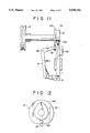
- FIG. 1 is a front elevational view, partly in cross section, of a button setting machine incorporating an apparatus for protecting an optical position indicator from collision with a punch of the button setting machine according to the present invention
- FIG. 2 is an enlarged cross-sectional view taken along line II--II of FIG. 1;
- FIG. 3 is a diagrammatical front elevational view showing the general construction of a collision protection apparatus according to another embodiment
- FIG. 4 is a view similar to FIG. 3, but showing the construction of a modified collision protection apparatus
- FIG. 5 is a diagrammatical front elevational view showing a collision protection apparatus according to another embodiment
- FIG. 6 is a view similar to FIG. 5, but showing a modified form of the collision protection apparatus
- FIG. 7 is a diagrammatical front elevational view showing the general construction of a collision protection apparatus according to still another embodiment of the invention.
- FIG. 8 is a right side view of FIG. 7;
- FIG. 9 is a view similar to FIG. 7, but showing a modified collision protection apparatus
- FIG. 10 is a right side view of FIG. 9;
- FIG. 11 is a diagrammatical front elevational view of a collision protection apparatus according to another embodiment of the invention.
- FIG. 12 is an enlarged view of a composite cam incorporated in the collision protection apparatus shown in FIG. 11.
- FIG. 1 there is shown a button setting machine for assembling upper and lower elements (not shown) of a garment fastener, such as a button, a stud button or a snap fastener, in clinched condition with a garment fabric sandwiched therebetween.
- the button setting machine includes an apparatus for protecting an optical indicator composed of a light projector from collision with a punch of the button setting machine according to the present invention.
- the button setting machine includes a punch 1 for forcing the upper fastener element into clinching engagement with the lower fastener element.
- the punch 1 is reciprocable vertically with respect to a frame 2 of the button setting machine.
- a die 3 is supported by the frame 2 directly below the punch 1 for holing thereon the lower fastener element.
- the punch 1 and the die 3 cooperate with each other to clinch the upper and lower fastener elements with a garment fabric disposed therebetween.
- the die 3 is connected at its lower end to one end of a lever 4 which is connected at its opposite end to a shock absorber (not shown) for taking up or absorbing a shock force applied to the die 3 when the upper and lower fastener elements are clinched together.
- the button setting machine further includes an upper pusher 5 for receiving an upper fastener element at a time from an upper chute 6 and for supplying the upper fastener element to an upper pocket or holder (not shown) disposed immediately below the punch 1 for holding the upper fastener element.
- the upper pusher 5 is pivoted to an upper pusher lever 7 so that it is movable alternately back and forth along a horizontal path in response to the pivotal movement of the upper pusher lever 7.
- the upper pusher 5 carries on its under side an optical position indicator 8 for indicating a position of the garment fabric where the upper and lower fastener elements are to be attached.
- the optical position indicator 8 comprises a light projector.
- a lower pusher 9 is movably supported on the frame 2 for receiving a lower fastener element at a time from a lower chute 10 and for supplying the lower fastener element to the die 3.
- the lower pusher 9 is pivoted to a lower pusher lever 11 and horizontally reciprocable in response to the pivotal movement of the lower pusher lever 11.
- the lower pusher lever 11 is urged by a tension coil spring 11a to turn counterclockwise in FIG. 1 for normally holding the lower pusher 9 in its fully advanced position.
- the forward end of the lower pusher 9 is disposed behind (left side in FIG. 1) the lower end of the lower chute 10.
- the punch 1, the upper pusher 5 including the light projector 8, and the lower pusher 9 are all driven by a common drive unit including a fly wheel 12 continuously rotated by an electric motor via a V-belt (neither shown).
- a radial disk cam 13 is concentrically mounted on a central shaft of the fly wheel 12 via a single-revolution clutch (not shown).
- the single-revolution clutch is engaged to connect the continuously rotating fly wheel 12 and the cam 13 when a foot pedal (not shown) is depressed. When the cam 13 completes one revolution, the single-revolution clutch is disengaged to separate the cam 13 from the continuously rotating fly wheel 12.
- the cam 13 has an eccentric pin 14 projecting from an end face thereof and pivoted to a lower end of a crank lever 15.
- the crank lever 15 is directly connected at its upper end with a shaft 16 slidably received in a cylinder member 17.
- the shaft 16 has an actuator in the form of an annular flange 18 engageable with the lower end of the cylinder member 17.
- the actuating flange 18 is spaced a distance D from the lower end of the cylinder member 17 when the punch 1 is in its uppermost position.
- the upper end of the cylinder member 17 is pivoted to one end of a T-shaped lever 19, the opposite end of the T-shaped lever 19 being operatively connected to an upper end of the punch 1.
- the T-shaped lever 19 is pivotally movable about a shaft 20 to reciprocate the punch 1 vertically toward and away from the die 3.
- the shaft 16 immediately starts moving upwardly into the cylinder member 17.
- pivotal movement of the T-shaped lever 19 does not occur until the annular actuating flange 18 on the shaft 16 abuts against the lower end of the cylinder member 17.
- the shaft 16 and the cylinder member 17 jointly constitute a lost motion mechanism 21 which produces the lost motion or the delay between the movement of a driver (cam 13 in the illustrated embodiment) and the movement of a follower (the T-shaped lever 19 in the illustrated embodiment).
- a vertical cam lever 22 is pivotally connected at its lower end to a horizontal shaft 24 secured to the frame 2 and has a roller follower 23 rollingly engageable with a cam surface 13a of the cam 13.
- the cam lever 22 is normally urged by a tension coil spring 25 in a direction to keep the roller follower 23 into contact with the cam surface of the cam 13.
- the cam lever 22 is pivoted at its upper end portion to one end of a horizontal actuating rod 26, the opposite end of the actuating rod 26 being connected with the upper pusher lever 7.
- connection between the actuating rod 26 and the upper pusher lever 7 is such that a small-diameter end portion 26a of the actuating rod 26 is slidably received in a hole in a bearing 7a provided on the upper pusher lever 7, as shown in FIG. 2.
- the T-shaped lever 19 has a vertical arm 30 extending downwardly from a substantially central portion of the lever 19 and pivotally connected at its distal end to one end of an expansion pipe joint 31.
- the opposite end of the expansion pipe joint 31 is pivoted to the lower pusher lever 11 adjacent to an upper end thereof.
- the expansion pipe joint 31 is composed of an outer pipe 32 connected to the arm 30 and an inner pipe 33 connected to the lower pusher lever 11 and slidably received in the outer pipe 32.
- a tension coil spring 27 acts between the lower pusher lever 11 and the lower pusher 9 to urge the latter slightly upwardly so as not to sink the forward end of the lower pusher 9.
- a tension coil spring 28 acts between the upper pusher lever 7 and the upper pusher 5 to urge the latter slightly upwardly for holding the horizontal posture of the upper pusher 5.
- a stopper 29 is disposed behind the upper pusher lever 7 and engageable with the same to limit backward or retracting movement of the upper pusher 5.
- the stopper 29 comprises a stop bolt and hence is adjustable in position so that the backward stroke of the upper pusher 5 can be adjusted.
- the upper pusher lever 7 is urged by a tension coil spring 34 to turn clockwise toward the stopper 29.
- the upper pusher lever 7 is turned counterclockwise against the force of the tension coil spring 34 when the actuating rod 26 is advanced toward the upper pusher lever 7. Due to the loose fitting connection between the small-diameter end portion 26a of the actuating rod 26 and the bearing 7a on the upper pusher lever 7, retracting movement of the actuating rod 26 permits the upper pusher lever 7 to turn clockwise under the force of the tension coil spring 34, thereby retracting the upper pusher 5 and the light projector 8.
- the button setting machine of the foregoing construction operates as follows. For purposes of illustration, operation of the button setting machine begins from a condition shown in FIG. 1 where the punch 1 is fully retracted, while the upper and lower pushers 5, 9 are fully advanced so that an upper fastener element is held by the upper holder below the punch 1 and a lower fastener element is placed on the die 3.
- the light projector 8 mounted on the upper pusher 5 assumes its advanced position.
- a start switch (not shown) of the button setting machine is turned on, the motor-driven fly wheel 12 rotates continuously.
- the single-revolution clutch is in the disengaged state so that the rotational movement of the fly wheel 12 is not transmitted to the cam 13.
- the light projector 8 projects a light beam passing along a common vertical axis of the punch 1 and the die 3. The light beam produces a light spot on a garment fabric when the latter is disposed between the light projector 8 and the die 3.
- a foot pedal is depressed whereupon the single-revolution clutch is engaged to connect the continuously rotating fly wheel 12 and the cam 13, thereby rotating the cam 13 in the clockwise direction as indicated by the arrow shown in FIG. 1.
- the clockwise movement of the cam 13 causes the roller follower 23 to relatively move from a flat cam surface to an arcuate cam surface 13a so that the cam lever 22 is turned counterclockwise about the shaft 24 against the force of the tension coil spring 25.
- the actuating rod 26 is retracted whereupon the upper pusher lever 7 is permitted to turn clockwise under the force of the tension coil spring 34 until it assumes its fully retracted position indicated by the phantom lines.
- the upper pusher 5 and the light projector 8 mounted thereon are retracted away from a vertical path of movement of the punch 1.
- the retracting movement of the upper pusher 5 and the light projector 8 is completed before the cam 13 advances through an angular distance which is equivalent to a linear advancing movement of the shaft 16 over the distance D (i.e., the lost motion) provided by the lost motion mechanism 21.
- the T-shaped lever 19 is kept immovable so that downward movement of the punch 1 never occurs before the upper pusher 5 and the light projector 8 are fully retracted.
- a continuing clockwise movement of the cam 13 causes the eccentric pin 14 to further advance the shaft 16 into the cylinder member 17 whereupon the annular actuating flange 18 on the shaft 16 is brought into abutment with the lower end of the cylinder member 17. Thereafter, the shaft 16 and the cylinder member 17 move upwardly in unison with each other against the force of a tension coil spring 35 so that the T-shaped lever 19 is turned about the shaft 20 in the clockwise direction to thereby lower the punch 1 toward the die 3.
- the eccentric pin 14 is disposed in its uppermost position and the punch 1 is fully advanced. The upper and lower fastener elements are thus attached to the garment fabric accurately at the desired position.
- the eccentric pin 14 moves from its uppermost position toward its lowermost position. Consequently, the cylinder member 17 is lowered by the force of the tension coil spring 35 whereby the T-shaped lever 19 is turned counterclockwise to thereby retract the punch 1 upwardly away from the die 3.
- the downward movement of the cylinder member 17 is limited to such an extent that the distance D is provided between the annular actuating flange 18 and the lower end of the cylinder member 17 when the eccentric pin 14 is disposed in its lowermost position.
- the downward movement of the cylinder member 17 is limited by a stopper 44 which is provided on the frame 2 and engageable with the T-shaped lever 19 to limit its pivotal movement in the counterclockwise direction.
- the single revolution clutch is disengaged to thereby separate the cam 13 from the continuously rotating fly wheel 12.
- the cam 13 is disposed in its initial position and hence the cam lever 22 is turned about the shaft 24 clockwise by the force of the tension coil spring 25.
- the clockwise movement of the cam lever 22 advances the actuating rod 26 to turn the upper pusher lever 7 counterclockwise, thereby advancing the upper pusher 5 and the light projector 8 into a position directly below the punch 1.
- the punch 1 descends only after the upper pusher 5 and the light projector 8 are fully retracted away from the vertical path of movement of the punch 1. Accordingly, collision or accidental interference between the light projector 8 and the punch 1 can be completely avoided even when the light projector 8 is disposed near the lower end of the punch 1. With this timed relation between the movement of the punch 1 and the movement of the light projector 8, the provision of the light projector 8 does not increase the stroke of the punch 1 and hence the overall size of the button setting machine is relatively small.
- FIG. 3 diagrammatically shows a portion of the button setting machine having a collision protection apparatus according to another embodiment of the present invention.
- the collision protection apparatus is similar to the apparatus shown in FIG. 1 but differs therefrom in that the punch 1 is pivoted at its upper end to one lever of a toggle joint 40, and that the cylinder member 17 of a lost motion mechanism 21 is pivotally connected at its upper end to one end of a L-shaped lever or bell-crank 41, the opposite end of the bell-crank 41 being connected with the toggle joint 40 via a link 42.
- the cam lever 22 is pivoted leftward to thereby retract the light projector 8 attached to the upper pusher 5, then the cylinder member 17 moves upwardly to turn the bell-crank 41 clockwise about a shaft 43 whereupon the toggle joint 40 is expanded by the link 42 to thereby lower the punch 1.
- the retracting movement of the light projector 8 begins while the punch 1 is at rest in the uppermost position, and the downward movement of the punch 1 is started after the light projector 8 is retracted from the vertical path of movement of the punch 1. Accordingly, the light projector 8 is protected from collision with the punch 1.
- Designated by 44 is a stopper engageable with the bell-crank 41 to provide a distance D between the annular actuating flange 18 and the cylinder member 17, that is, the delay between the retracting movement of the light projector 8 and the downward movement of the punch 1.
- a modified collision protection apparatus shown in FIG. 4 is substantially the same as the apparatus shown in FIG. 1 with the exception that the cam 13 is a composite cam having a first cam surface 50 profiled to retract the light projector 8, and a second cam surface 51 profiled to vertically reciprocate the punch 1, the first cam surface 50 being eccentric to the axis of rotation of the cam 13 and the second cam surface 51.
- the cam 13 is rotated in the direction of the arrow, the first cam surface 50 urges the roller follower 23 outwardly (leftward in FIG. 4).
- the cam lever 22 is therefore turned counterclockwise about the shaft 24 to thereby retract the actuating rod 26.
- the second cam surface 51 has an approximately pear-shaped profile having a circular curve of a constant radius of curvature which is concentric with the axis of rotation of the cam 13 and extends over a substantial part of the full circumference of the cam profile. A portion of the second cam surface having the constant radium of curvature continuously engages a roller follower 52 until the cam 13 moves through a predetermined angular distance a.
- the length of the pause in motion corresponds to the delay between the retracting movement of the light projector 8 and the downward movement of the punch 1 which is produced by the distance D provided by the lost motion mechanism 21 described with respect to the foregoing embodiments shown in FIGS. 1 and 3.
- the second cam surface 51 and the connecting rod 53 having the roller follower 52 jointly constitutes a modified delay producing mechanism.
- the upward movement of the punch 1 is achieved by the force of a tension coil spring 54 acting on the T-shaped lever 19.
- FIG. 5 shows a portion of the button setting machine incorporating a collision protection apparatus according to a fourth embodiment of the present invention.
- the collision protection apparatus is similar to the apparatus shown in FIG. 1 but differs therefrom in the construction of a lost motion mechanism.
- the lost motion mechanism includes an elongate vertical lever 60 having an oblong hole 61 extending longitudinally along an upper end portion of the vertical lever 60, and a pin 62 movably received in the oblong hole 60 and connected to one end of the T-shaped lever 19.
- the oblong hole 61 has a length D which is equal to the distance D provided by the lost motion mechanism 21 shown in FIG. 1.
- the cam 13 is rotated in the direction of the arrow whereupon the cam lever 22 is caused to turn about the shaft 24 in the counterclockwise direction.
- This pivotal movement of the cam lever 22 causes the light projector 8 to retract from the vertical path of movement of the punch 1 under the force of the tension coil spring 34.
- the vertical lever 60 is lifted, however, the upward movement of the vertical crank lever 60 is not transmitted to the T-shaped lever 19 because the pin 62 simply slides along the oblong hole 61 in the crank lever 60.
- the pivotal movement of the T-shaped lever 19 tending to lower the punch 1 begins when the pin 62 engages a lower end edge of the oblong hole 61.
- the pin 62 is normally held in contact with the upper end edge of the oblong hole 61 by a stopper 44 acting on the T-shaped lever 19.
- the length D of the oblong hole 61 is selected such that the pin 62 is brought into engagement with the lower end edge of the oblong hole 61 to thereby turn the T-shaped lever 19 clockwise for lowering the punch 1 when the light projector 8 is retracted from the vertical path of movement of the punch 1.
- a modified collision protection apparatus shown in FIG. 6 includes a rotating circular disk 70 driven by a power-driven fly wheel (see FIG. 1), and an elongate vertical lever cam 71 operatively connected at its lower end to an eccentric pin 14 secured to the circular disk 70.
- the lever cam 71 has an oblong hole 61 extending longitudinally along an upper end portion thereof and movably receiving therein a pin 61 connected to one end of the T-shaped lever 19, and a cam surface 71a extending along a length of one longitudinal edge of the lever cam 71 and acting on a roller follower 72 mounted on one end of a bell-crank 73.
- the other end of the bell-crank 73 is pivotally connected to an end of the actuating rod 26.
- a continuing upward movement of the lever cam 71 causes the lower end edge of the oblong hole 61 to engage the pin 62 and then turn the T-shaped lever 19 in the clockwise direction, thereby lowering the punch 1.
- the length of the oblong hole 61 is selected such that the engagement of the lower end edge of the oblong hole 61 and the pin 62 occurs when the light projector 8 is retracted from the vertical path of movement of the punch 1.
- FIGS. 7 and 8 diagrammatically illustrate a collision protection apparatus according to a sixth embodiment of the present invention.
- the apparatus includes an L-shaped lever 81 pivotally movable about a horizontal shaft 82.
- the L-shaped lever 81 carries on its upper end a roller follower 80 engageable with a cam surface 13a of the rotating cam 13 and is pivotally connected to the upper pusher 5.
- the L-shaped lever 81 turns clockwise to thereby retract the light projector 8 from the vertical path of movement of the punch 1.
- the cam 13 has an eccentric pin 14 connected to an upper end of a crank 15.
- the lower end of the crank 15 is connected with a cylinder member 17 which slidably receives a shaft 83 projecting outwardly from an upper end of the punch 1.
- the upper end of the punch 1 is normally spaced from the cylinder member 17 by a distance D.
- a stopper 44 is provided to limit the upward movement of the punch 1 as the punch is lifted by the force of a tension coil spring 35.
- the cylinder member 17 and the shaft 83 thus spaced jointly constitute a lost motion mechanism which provides the delay between the retracting movement of the light projector 8 and the downward movement of the punch 1. With this lost motion mechanism, a start of the downward movement of the punch 1 is retarded until the cylinder member 17 impinges upon the upper end of the punch 1, in which instance the light projector 8 is rearwardly offset from the vertical path of movement of the punch 1. Since the cylinder member 17 and the L-shaped lever 81 are directly connected with the punch 1 and the upper pusher 5, respectively, the button setting machine of this embodiment is simpler in construction than the button setting machine of any of the foregoing embodiments.
- FIGS. 9 and 10 show a modified form of the collision protection apparatus according to the present invention.
- the modified apparatus is substantially the same as the apparatus shown in FIGS. 7 and 8, excepting that the lost motion mechanism is composed of an oblong hole 91 formed longitudinally in an elongate vertical connecting member 90 pivotally connected to the crank 15, and a horizontal pin 92 extending transversely across a recessed upper end portion of the punch 1 and slidably received in the oblong hole 91.
- the connecting member 90 is moved downwardly, however, due to the lost motion mechanism, the downward movement of the connecting member 90 is not transmitted to the punch 1 until the upper end edge of the oblong hole 91 engages the pin 92 on the punch 1.
- the L-shaped lever 81 turns clockwise under the action of the cam surface 13a to thereby retract the light projector 8 from the vertical path of movement of the punch 1.
- the connector member 90 further moves downward, the upper end edge of the oblong hole 91 is brought into engagement with the pin 2 and then urges the pin 92 downwardly to thereby lower the punch 1.
- FIGS. 11 and 12 diagrammatically show a part of a button setting machine incorporating a modified collision protection apparatus according to another embodiment of the present invention.
- the apparatus is similar to the apparatus shown in FIGS. 7 and 8 but differs therefrom in that the cam 13 is a composite cam including a first cam surface 100 having a cam profile which is capable of oscillating the L-shaped lever 81 via the roller follower 80 for retracting the light projector 8 from the vertical path of movement of the punch 1, and a second cam surface 100 concentric with the first cam surface 101 and having a cam profile which is capable of lowering the punch 1 via a roller follower 102 rotatably mounted on an upper end of the punch 1.
- the roller follower 80 on the L-shaped lever 81 rides on the first cam surface 100, thereby causing the L-shaped lever 81 to pivot in a direction to retract the light projector 8 from the vertical path of movement of the punch 1.
- the roller follower 102 on the punch 1 rolls along a portion of the second cam surface 101 which has a cam profile of a constant radius of curvature. Consequently, the second cam surface 101 does not produce a camming action tending to lower the punch 1.
- the second cam surfaces 101 urges the roller follower 102 downwardly to thereby lower the punch 1.
- first and second cam surfaces 100, 101 are so profiled as to create the delay between the retracting movement of the light projector 8 and the downward movement of the punch 1.
- the punch 1 is returned to its uppermost position under the force of the tension coil spring 103.
- the radial disk cam 13 may be substituted by a face cam having first and second cam surfaces on its one side.
- a face cam having two grooves in its opposite surfaces may be employed in place of the radial disk cam 13.
Landscapes
- Engineering & Computer Science (AREA)
- General Engineering & Computer Science (AREA)
- Mechanical Engineering (AREA)
- Textile Engineering (AREA)
- Presses And Accessory Devices Thereof (AREA)
- Perforating, Stamping-Out Or Severing By Means Other Than Cutting (AREA)
- Portable Nailing Machines And Staplers (AREA)
- Projection Apparatus (AREA)
- Slide Fasteners, Snap Fasteners, And Hook Fasteners (AREA)
- Investigating Strength Of Materials By Application Of Mechanical Stress (AREA)
Applications Claiming Priority (2)
| Application Number | Priority Date | Filing Date | Title |
|---|---|---|---|
| JP1026299A JPH02206401A (ja) | 1989-02-03 | 1989-02-03 | 投光器の衝突防止方法及びその装置 |
| JP1-26299 | 1989-02-03 |
Publications (1)
| Publication Number | Publication Date |
|---|---|
| US5048741A true US5048741A (en) | 1991-09-17 |
Family
ID=12189460
Family Applications (1)
| Application Number | Title | Priority Date | Filing Date |
|---|---|---|---|
| US07/468,910 Expired - Fee Related US5048741A (en) | 1989-02-03 | 1990-01-23 | Apparatus for protecting light projector from collision with punch of button setting machine |
Country Status (6)
| Country | Link |
|---|---|
| US (1) | US5048741A (es) |
| EP (1) | EP0381226B1 (es) |
| JP (1) | JPH02206401A (es) |
| CA (1) | CA2008468C (es) |
| DE (1) | DE69011886T2 (es) |
| ES (1) | ES2059846T3 (es) |
Cited By (7)
| Publication number | Priority date | Publication date | Assignee | Title |
|---|---|---|---|---|
| US5263627A (en) * | 1991-05-31 | 1993-11-23 | Schaeffer Gmbh | Machine for attaching buttons, rivets or the like, preferably to articles of clothing |
| DE4408691C1 (de) * | 1994-03-15 | 1995-08-17 | Stocko Metallwarenfab Henkels | Maschine zum Ansetzen von Nieten, Druckknöpfen und dergleichen |
| EP0672359A2 (de) * | 1994-03-15 | 1995-09-20 | Stocko Verschlusstechnik GmbH & Co. | Vorrichtung für die Zuführung von Montageteilen |
| US6131786A (en) * | 1997-01-09 | 2000-10-17 | Ykk Corporation | Device for setting rivets, buttons or the like on textiles |
| US6196438B1 (en) * | 1998-05-20 | 2001-03-06 | Ykk Europe Ltd. | Fixing machine |
| US20050242153A1 (en) * | 2004-04-20 | 2005-11-03 | Acco Brands, Inc. | Stapler |
| CN106539173A (zh) * | 2017-01-17 | 2017-03-29 | 温州大学 | 一种钉扣机 |
Families Citing this family (3)
| Publication number | Priority date | Publication date | Assignee | Title |
|---|---|---|---|---|
| JP2560219Y2 (ja) * | 1991-05-14 | 1998-01-21 | ワイケイケイ株式会社 | 釦取付機用投光装置 |
| DE19533594C1 (de) * | 1995-09-11 | 1997-04-10 | Stocko Fasteners Gmbh | Ansetzvorrichtung |
| CN103689848B (zh) * | 2013-12-30 | 2015-08-19 | 周树芬 | 一种纽扣装订机 |
Citations (5)
| Publication number | Priority date | Publication date | Assignee | Title |
|---|---|---|---|---|
| US3964661A (en) * | 1974-10-23 | 1976-06-22 | Textron, Inc. | Apparatus for attaching pronged and mating elements to articles |
| US4605150A (en) * | 1983-12-29 | 1986-08-12 | Nippon Notion Kogyo Co., Ltd. | Button setting apparatus with optical position indicator |
| GB2191139A (en) * | 1986-05-28 | 1987-12-09 | Scovill Japan | Button-setting position indicator |
| EP0255913A2 (en) * | 1986-08-06 | 1988-02-17 | Yoshida Kogyo K.K. | Apparatus for assembling pairs of garment fastener elements |
| EP0261361A2 (en) * | 1986-08-26 | 1988-03-30 | Yoshida Kogyo K.K. | Garment fastener assembling apparatus with ram-driven position indicator |
Family Cites Families (3)
| Publication number | Priority date | Publication date | Assignee | Title |
|---|---|---|---|---|
| JPS491108U (es) * | 1972-04-07 | 1974-01-08 | ||
| DE3143941C2 (de) * | 1981-11-05 | 1983-09-15 | Deutsche Thomson-Brandt Gmbh, 7730 Villingen-Schwenningen | Vorrichtung für eine Bauteile-Bestückungsmaschine zur Zuführung von gepolten, elektronischen Bauteilen |
| JPS6315304U (es) * | 1986-07-17 | 1988-02-01 |
-
1989
- 1989-02-03 JP JP1026299A patent/JPH02206401A/ja active Pending
-
1990
- 1990-01-23 US US07/468,910 patent/US5048741A/en not_active Expired - Fee Related
- 1990-01-24 CA CA002008468A patent/CA2008468C/en not_active Expired - Fee Related
- 1990-02-02 ES ES90102084T patent/ES2059846T3/es not_active Expired - Lifetime
- 1990-02-02 DE DE69011886T patent/DE69011886T2/de not_active Expired - Fee Related
- 1990-02-02 EP EP90102084A patent/EP0381226B1/en not_active Expired - Lifetime
Patent Citations (7)
| Publication number | Priority date | Publication date | Assignee | Title |
|---|---|---|---|---|
| US3964661A (en) * | 1974-10-23 | 1976-06-22 | Textron, Inc. | Apparatus for attaching pronged and mating elements to articles |
| US4605150A (en) * | 1983-12-29 | 1986-08-12 | Nippon Notion Kogyo Co., Ltd. | Button setting apparatus with optical position indicator |
| GB2191139A (en) * | 1986-05-28 | 1987-12-09 | Scovill Japan | Button-setting position indicator |
| US4723357A (en) * | 1986-05-28 | 1988-02-09 | Scovill Japan Kabushiki Kaisha | Buttoning apparatus with optical attaching-position indicator |
| EP0255913A2 (en) * | 1986-08-06 | 1988-02-17 | Yoshida Kogyo K.K. | Apparatus for assembling pairs of garment fastener elements |
| EP0261361A2 (en) * | 1986-08-26 | 1988-03-30 | Yoshida Kogyo K.K. | Garment fastener assembling apparatus with ram-driven position indicator |
| US4765524A (en) * | 1986-08-26 | 1988-08-23 | Yoshida Kogyo K.K. | Garment-fastener assembling apparatus with ram-driven position indicator |
Cited By (11)
| Publication number | Priority date | Publication date | Assignee | Title |
|---|---|---|---|---|
| US5263627A (en) * | 1991-05-31 | 1993-11-23 | Schaeffer Gmbh | Machine for attaching buttons, rivets or the like, preferably to articles of clothing |
| DE4408691C1 (de) * | 1994-03-15 | 1995-08-17 | Stocko Metallwarenfab Henkels | Maschine zum Ansetzen von Nieten, Druckknöpfen und dergleichen |
| EP0672359A2 (de) * | 1994-03-15 | 1995-09-20 | Stocko Verschlusstechnik GmbH & Co. | Vorrichtung für die Zuführung von Montageteilen |
| US5501001A (en) * | 1994-03-15 | 1996-03-26 | Stocko Verschlusstechnik Gmbh & Co. | Machine for mounting rivets, snaps and the like |
| EP0672359A3 (de) * | 1994-03-15 | 1996-06-19 | Stocko Verschlusstechnik Gmbh | Vorrichtung für die Zuführung von Montageteilen. |
| US5588326A (en) * | 1994-03-15 | 1996-12-31 | Stocko Fasteners Gmbh | Feeding device for parts to be mounted |
| US6131786A (en) * | 1997-01-09 | 2000-10-17 | Ykk Corporation | Device for setting rivets, buttons or the like on textiles |
| US6196438B1 (en) * | 1998-05-20 | 2001-03-06 | Ykk Europe Ltd. | Fixing machine |
| US20050242153A1 (en) * | 2004-04-20 | 2005-11-03 | Acco Brands, Inc. | Stapler |
| CN106539173A (zh) * | 2017-01-17 | 2017-03-29 | 温州大学 | 一种钉扣机 |
| CN106539173B (zh) * | 2017-01-17 | 2018-06-05 | 温州大学 | 一种钉扣机 |
Also Published As
| Publication number | Publication date |
|---|---|
| CA2008468A1 (en) | 1990-08-03 |
| EP0381226B1 (en) | 1994-08-31 |
| CA2008468C (en) | 1995-08-01 |
| EP0381226A3 (en) | 1990-11-14 |
| EP0381226A2 (en) | 1990-08-08 |
| DE69011886T2 (de) | 1995-04-13 |
| DE69011886D1 (de) | 1994-10-06 |
| JPH02206401A (ja) | 1990-08-16 |
| ES2059846T3 (es) | 1994-11-16 |
Similar Documents
| Publication | Publication Date | Title |
|---|---|---|
| US5048741A (en) | Apparatus for protecting light projector from collision with punch of button setting machine | |
| US4044462A (en) | Rivet blank feeder for riveting apparatus | |
| US4799611A (en) | Apparatus for assembling pairs of garment fastener elements | |
| US3792521A (en) | Combination slider assembling and end stop applying apparatus | |
| US4615473A (en) | Apparatus for assembling a pair of fastener elements | |
| EP0391747B1 (en) | Single cut die set | |
| US4378900A (en) | Machine with fingerguard | |
| EP0381227B1 (en) | Stroke adjustment apparatus for light projector of button setting machine | |
| EP0142806A2 (en) | Apparatus for assembling a pair of fastener elements | |
| EP0173248B1 (en) | Apparatus for assembling a pair of fastener elements | |
| EP0212502B1 (en) | Fastener-assembling apparatus with safety device | |
| US2800814A (en) | Slug-positioner for ball-making machines | |
| CA1292448C (en) | Garment-fastener assembling apparatus with ram-driven position indicator | |
| CA1232567A (en) | Button orientation apparatus | |
| JPS5921691B2 (ja) | 衝撃プレス | |
| US1983384A (en) | Wire-stitching machine | |
| US4020721A (en) | Apparatus and method for cutting continuous stock | |
| GB2138453A (en) | Apparatus for attaching fastener elements onto a garment | |
| JPH0659248B2 (ja) | スライドファスナ−の部品取付け装置 | |
| US4056870A (en) | Hand held powered metal clinching tool | |
| EP0083111B1 (en) | Method and apparatus for securing bottom end stop to fastener chain | |
| US2997781A (en) | Indexing mechanism for assembling machine or the like | |
| US800425A (en) | Can-seaming machine. | |
| US1255201A (en) | Differential motion for wire-stitchers or like machines. | |
| GB2039046A (en) | Apparatus and method for automatic selection and delivery of assembled bodies |
Legal Events
| Date | Code | Title | Description |
|---|---|---|---|
| AS | Assignment |
Owner name: YOSHIDA KOGYO, K.K., A CORP. OF JAPANESE, JAPAN Free format text: ASSIGNMENT OF ASSIGNORS INTEREST.;ASSIGNORS:TOISHI, YOSHIYUKI;SODENO, TOSHIAKI;REEL/FRAME:005222/0972 Effective date: 19900105 |
|
| FPAY | Fee payment |
Year of fee payment: 4 |
|
| AS | Assignment |
Owner name: YKK CORPORATION, JAPAN Free format text: CHANGE OF NAME;ASSIGNOR:YOSHIDA KOGYO K.K.;REEL/FRAME:007378/0851 Effective date: 19940801 |
|
| FEPP | Fee payment procedure |
Free format text: PAYOR NUMBER ASSIGNED (ORIGINAL EVENT CODE: ASPN); ENTITY STATUS OF PATENT OWNER: LARGE ENTITY |
|
| FPAY | Fee payment |
Year of fee payment: 8 |
|
| REMI | Maintenance fee reminder mailed | ||
| LAPS | Lapse for failure to pay maintenance fees | ||
| STCH | Information on status: patent discontinuation |
Free format text: PATENT EXPIRED DUE TO NONPAYMENT OF MAINTENANCE FEES UNDER 37 CFR 1.362 |
|
| FP | Lapsed due to failure to pay maintenance fee |
Effective date: 20030917 |