US4985838A - Traction control apparatus - Google Patents
Traction control apparatus Download PDFInfo
- Publication number
- US4985838A US4985838A US07/339,703 US33970389A US4985838A US 4985838 A US4985838 A US 4985838A US 33970389 A US33970389 A US 33970389A US 4985838 A US4985838 A US 4985838A
- Authority
- US
- United States
- Prior art keywords
- torque
- output
- vehicle
- calculating
- driving wheel
- Prior art date
- Legal status (The legal status is an assumption and is not a legal conclusion. Google has not performed a legal analysis and makes no representation as to the accuracy of the status listed.)
- Expired - Lifetime
Links
Images




Classifications
-
- B—PERFORMING OPERATIONS; TRANSPORTING
- B60—VEHICLES IN GENERAL
- B60T—VEHICLE BRAKE CONTROL SYSTEMS OR PARTS THEREOF; BRAKE CONTROL SYSTEMS OR PARTS THEREOF, IN GENERAL; ARRANGEMENT OF BRAKING ELEMENTS ON VEHICLES IN GENERAL; PORTABLE DEVICES FOR PREVENTING UNWANTED MOVEMENT OF VEHICLES; VEHICLE MODIFICATIONS TO FACILITATE COOLING OF BRAKES
- B60T8/00—Arrangements for adjusting wheel-braking force to meet varying vehicular or ground-surface conditions, e.g. limiting or varying distribution of braking force
- B60T8/32—Arrangements for adjusting wheel-braking force to meet varying vehicular or ground-surface conditions, e.g. limiting or varying distribution of braking force responsive to a speed condition, e.g. acceleration or deceleration
- B60T8/58—Arrangements for adjusting wheel-braking force to meet varying vehicular or ground-surface conditions, e.g. limiting or varying distribution of braking force responsive to a speed condition, e.g. acceleration or deceleration responsive to speed and another condition or to plural speed conditions
-
- B—PERFORMING OPERATIONS; TRANSPORTING
- B60—VEHICLES IN GENERAL
- B60T—VEHICLE BRAKE CONTROL SYSTEMS OR PARTS THEREOF; BRAKE CONTROL SYSTEMS OR PARTS THEREOF, IN GENERAL; ARRANGEMENT OF BRAKING ELEMENTS ON VEHICLES IN GENERAL; PORTABLE DEVICES FOR PREVENTING UNWANTED MOVEMENT OF VEHICLES; VEHICLE MODIFICATIONS TO FACILITATE COOLING OF BRAKES
- B60T8/00—Arrangements for adjusting wheel-braking force to meet varying vehicular or ground-surface conditions, e.g. limiting or varying distribution of braking force
- B60T8/17—Using electrical or electronic regulation means to control braking
- B60T8/175—Brake regulation specially adapted to prevent excessive wheel spin during vehicle acceleration, e.g. for traction control
-
- B—PERFORMING OPERATIONS; TRANSPORTING
- B60—VEHICLES IN GENERAL
- B60G—VEHICLE SUSPENSION ARRANGEMENTS
- B60G2800/00—Indexing codes relating to the type of movement or to the condition of the vehicle and to the end result to be achieved by the control action
- B60G2800/90—System Controller type
- B60G2800/92—ABS - Brake Control
-
- B—PERFORMING OPERATIONS; TRANSPORTING
- B60—VEHICLES IN GENERAL
- B60G—VEHICLE SUSPENSION ARRANGEMENTS
- B60G2800/00—Indexing codes relating to the type of movement or to the condition of the vehicle and to the end result to be achieved by the control action
- B60G2800/90—System Controller type
- B60G2800/95—Automatic Traction or Slip Control [ATC]
-
- B—PERFORMING OPERATIONS; TRANSPORTING
- B60—VEHICLES IN GENERAL
- B60G—VEHICLE SUSPENSION ARRANGEMENTS
- B60G2800/00—Indexing codes relating to the type of movement or to the condition of the vehicle and to the end result to be achieved by the control action
- B60G2800/90—System Controller type
- B60G2800/97—Engine Management System [EMS]
Definitions
- the present invention relates to a traction control apparatus for preventing slippage of driving wheels in an acceleration state.
- An apparatus for preventing slippage of driving wheels of a vehicle in an acceleration state as disclosed in U.S. Pat. No. 4,637,487, or the like, is known.
- a main throttle valve whose opening is controlled in cooperation with an accelerator pedal and a sub throttle valve whose opening is electrically controlled are arranged in an air intake path of an engine.
- the opening of the sub throttle valve is controlled to be decreased, thereby reducing an engine output, and eliminating slippage of the driving wheels.
- a traction control apparatus comprises:
- driving wheel velocity detecting means for detecting a driving wheel velocity of the vehicle
- driven wheel velocity detecting means for detecting a driven wheel velocity of the vehicle
- reference velocity setting means for setting a reference velocity on the basis of an output from said driven wheel velocity detecting means
- slip value detecting means for detecting a slip value of the driving wheel on the basis of a difference between the driving wheel velocity and the reference velocity.
- control start instruction means for outputting at least an engine control start signal when a slip state of the driving wheel including at least the slip value satisfies a predetermined control start condition
- vehicle acceleration calculating means for calculating a vehicle acceleration of the vehicle on the basis of the output from said driven wheel velocity detecting means
- reference drive torque calculating means for calculating a reference drive torque on the basis of an output from said vehicle acceleration calculating means
- target output torque setting means for determining a target output torque of the engine in accordance with an output from said reference drive torque calculating means
- correction torque setting means for setting a correction torque on the basis of an output from said slip value detecting means
- drive torque control means for, when the engine control start signal is output, controlling an engine output of the vehicle in accordance with the corrected target output torque to control the drive torque of the driving wheel.
- a target engine output is determined by correcting a reference target torque according to a driving state of a vehicle by a correction torque corresponding to a slip value of driving wheels, and an engine output is controlled to reach the target engine output. Therefore, a traction control apparatus with high accuracy can be provided.
- FIG. 1B is a diagram showing a detailed arrangement of a traction controller shown in FIG. 1A;
- FIGS. 2A to 2C are block diagrams showing control of the traction controller shown in FIG. 1A in units of functional blocks;
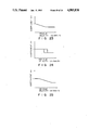
- FIG. 3 is a graph showing the relationship between a centripetal acceleration GY and a variable KG;
- FIG. 5 is a graph showing the relationship between a vehicle velocity VB and a variable KV;
- FIG. 9 is a graph showing the relationship between a slip rate S and a friction coefficient ⁇ of a road surface
- FIG. 10 is a graph showing the relationship between a vehicle acceleration GBF and a variable Kl;
- FIG. 11 is a graph showing the relationship between the slip value DV and a coefficient KI
- FIG. 13 is a graph showing the relationship between a target torque T ⁇ ' and an equivalent throttle opening ⁇ s';
- FIG. 15 is a graph showing the relationship between the centripetal acceleration GY and variation of coefficient Kp ⁇ Kp;
- FIG. 16 is a view showing the arrangement of the main throttle valve THm and a sub throttle valve THs;
- FIG. 17A is a diagram showing an overall arrangement of a traction control apparatus according to a second embodiment of the present invention.
- FIG. 17B is a diagram showing a detailed arrangement of a traction controller shown in FIG. 17A;
- FIG. 19 is a graph showing the relationship between a centripetal acceleration GY and a variable KG;
- FIG. 20 is a graph showing the relationship between the centripetal acceleration GY and a variable Kr;
- FIG. 21 is a graph showing the relationship between the centripetal acceleration GY and a slip value Vg;
- FIG. 22 is a graph showing the relationship between a changing value ⁇ GY of the centripetal acceleration GY as a function of time and the slip value Vd
- FIGS. 23 to 28 are graphs showing the relationship between a vehicle velocity VB and a coefficient KV;
- FIG. 30 is a graph showing the relationship between an changing value GFR (GFL) of a slip value DV as a function of time and a braking hydraulic pressure variation ⁇ P;
- FIG. 32 is a graph showing the relationship between a lower limit Tlim of a target engine torque and a time (tl) after traction control is started;
- FIG. 33 is a graph showing the relationship between the vehicle velocity VB and the lower limit Tlim of the target engine torque
- FIG. 35 is a view showing a state of a vehicle when it is turned
- FIG. 36 is a diagram showing an overall arrangement of a traction control apparatus according to a third embodiment of the present invention.
- FIG. 38 is a graph showing an output voltage of a lateral G sensor.
- FIG. 1A is a diagram showing a traction control apparatus for a vehicle.
- FIG. 1A illustrates a front-wheel drive vehicle.
- WFR denotes a front right wheel
- WFL a front left wheel
- WRR a rear right wheel
- WRL a rear left wheel.
- An engine 16 has a main throttle valve THm and a sub throttle valve THs, as shown in FIG. 16.
- the main throttle valve THm is operated by an accelerator pedal to adjust an engine output.
- a throttle opening ⁇ s of the sub throttle valve THs is controlled to control the engine output.
- Reference numeral 17 denotes a wheel cylinder for braking the front right wheel WFR; and 18, a wheel cylinder for braking the front left wheel WFL.
- Supply of a pressurized oil from an accumulator 19 to the wheel cylinder 17 is performed through an inlet valve 17i, and exhaustion of the pressurized oil from the wheel cylinder 17 to a reservoir 20 is performed through an outlet valve 17o.
- a normally-open right shut valve 202R is arranged on a right oil path 201R between a master cylinder 201 and the inlet valve 17i
- a normally-open left shut valve 202L is arranged on a left oil path 201L between the master cylinder 201 and the inlet valve 18i.
- the inlet valves 17i and 18i and the outlet valves 17o and 18o and shut valves 202R and 202L are open/close-controlled by the traction controller 15.
- the traction controller 15 receives a shift signal SHT from a transmission controller 151 for controlling switching of shift positions of an automatic transmission 16m.
- the SHT signal indicates a shift position of the automatic transmission 16m.
- the traction controller 15 also receives an engine speed signal Ne of the engine and an opening signal ⁇ m of the main throttle valve THm shown in FIG. 16.
- the traction controller 15 comprises an MPU (micro processor unit) 15p including various registers, an ALU (arithmetic and logic unit), and the like, a memory 15m for storing a traction control program, various maps, coefficient data, variable data, counters, and flags, and the like.
- MPU micro processor unit
- ALU arithmetic and logic unit
- the memory 15m stores the traction control program whose control content is shown in FIGS. 2A and 2B in units of functional blocks, a variable KG shown in FIG. 3, a variable KT shown in FIG. 4, a variable KV shown in FIG. 5, a GFR (GFL)- ⁇ P map shown in FIG. 6, a map showing the opening ⁇ m of the main throttle valve THm shown in FIG. 7, a variable Kl shown in FIG. 10, a coefficient KI shown in FIG. 11, ⁇ Kp shown in FIG. 12, a T ⁇ '- ⁇ s' map shown in FIG. 13, a ⁇ s map shown in FIG. 14, a ⁇ Kp map shown in FIG.
- a vehicle weight W and a wheel radius Re correction torques TSn and TPn, a target torque T ⁇ , a braking time FR of the right driving wheel, a braking time FL of the left driving wheel, a present vehicle acceleration GB n , an immediately preceding vehicle acceleration GB n-1 , a present vehicle acceleration GBF passed through a filter, an immediately preceding vehicle acceleration GBF n-1 passed through the filter, a timer tl for counting a time tl after traction control is started, a control flag CNT1 which is set when a start condition for starting engine output control is established and is reset when an end condition for ending the control is established, a control flag CNT2 which is set when a start condition for starting braking control is established and is reset when an end condition for ending the braking control is established, and a shift change flag CHFLG to which "1" is set for a predetermined period of time after a shift change operation is performed.
- the detailed arrangement of the traction controller 15 will be described below with reference to the block diagrams of FIGS. 2A to 2C showing the control of the traction controller 15 in units of functional blocks.
- the wheel velocities VFR and VFL of the driving wheels detected by the wheel velocity sensors 11 and 12 are averaged by an averaging section 21 to calculate an average wheel velocity (VFR+VFL)/2.
- the wheel velocities VFR, VFL, VRR, VRL are sent to a slip rate calculating section 111.
- slip rate S ##EQU1## is calculated.
- the wheel velocities VRR and VRL are sent to a drive state detecting section 112. In this section 112, various drive conditions are detected.
- a vehicle velocity VB and an acceleration of the vehicle and an centripental acceleration GY are calculated in section 112a, 112b, 112d on the basis of the wheel velocities VRR and VRL. And also a time t after traction control by braking is started is counted in timer T.
- the wheel velocities VFR and VFL of the driving wheels detected by the wheel velocity sensors 11 and 12 are sent to a low vehicle velocity selecting section (SL) 22, so that a lower vehicle velocity Vdl of the wheel velocities VFR and VFL is selected and output.
- the average wheel velocity Vde output from the averaging section 21 is multiplied with a variable K by a weighting section 23.
- the selected wheel velocity output from the SL 22 is multiplied with (1-K) by a weighting section 24.
- the outputs from the weighting sections 23 and 24 are added to each other by an adder 25.
- K a largest one of a variable KG which changes in accordance with a centripetal acceleration GY generated upon turning of a vehicle, the variable KT which changes along with the time t after slip control by braking is started, and the variable KV which changes in accordance with a vehicle velocity (driven wheel velocity) VB, as shown in FIGS. 3 to 5 is selected by a variable setting section 231.
- the wheel velocity output from the adder 25 is sent to a differential section 26 as a driving wheel velocity VF, so that a changing value of driving wheel velocity VF as a function of time, i.e., a driving wheel acceleration GW is calculated.
- the velocity VF is used for calculating a slip value DV of the driving wheel, as will be described later.
- the vehicle velocity VFR of the right driving wheel detected by the wheel velocity sensor 11 is sent to a subtractor 27, so that a reference driving wheel velocity V ⁇ (to be described later) is subtracted therefrom.
- the wheel velocity VFL of the left driving wheel detected by the wheel velocity sensor 12 is sent to a subtractor 28, so that the reference driving wheel velocity V ⁇ (to be described later) is subtracted therefrom.
- the output from the subtractor 27 is multiplied with KB set by the KB setting section 291 (0 ⁇ KB ⁇ 1) by a multiplier 29, and the output from the subtractor 28 is multiplied with (1-KB) by a multiplier 30. Thereafter, the outputs from the multipliers 29 and 30 are added to each other by an adder 31 to obtain a slip value DVFR of the right driving wheel WFR.
- the output from the subtractor 28 is multiplied with KB by a multiplier 32, and the output from the subtractor 27 is multiplied with (1-KB) by a multiplier 33. Thereafter, the outputs from the multipliers 32 and 33 are added to each other by an adder 34 to obtain a slip value DVFL of the left driving wheel WFL.
- the slip value DVFR of the right driving wheel WFR is differentiated by a differential section 35 to calculate its change as a function of time, i.e., a slip changing value GFR.
- the slip value DVFL of the left driving wheel WFL is differentiated by a differential section 36 to calculate its changing value as a function of time, i.e., a slip changing value GFL.
- the slip changing value GFR is sent to a braking hydraulic pressure variation ⁇ P calculating section 37 to obtain a braking hydraulic pressure variation ⁇ P necessary for suppressing the slip changing value GFR with reference to the GFR (GFL)- ⁇ P conversion map shown in FIG. 6.
- the slip changing value GFL is sent to a braking hydraulic pressure variation ⁇ P calculating section 38 to obtain a braking hydraulic pressure variation ⁇ P necessary for suppressing the slip changing value GFL with reference to the GFR (GFL)- ⁇ P conversion map shown in FIG. 6 (if DV>6 km/h, a larger one of ⁇ P and 2 kg/cm 2 is employed).
- the variation ⁇ P represents a variation in amount of liquid flowing in or flowing out through the inlet valve 17i (18i) or the outlet valve 17o (18o). More specifically, as the slip changing value GFR (GFL) is increased, ⁇ P is increased, and the driving wheels WFR and WFL are braked to decrease a driving torque.
- the braking hydraulic pressure variation ⁇ P, output from the ⁇ P calculating section 37 for suppressing the slip changing value GFR is supplied to a ⁇ P-T converter 40 for calculating open times T of the inlet valve 17i and the outlet valve 17o through a switch 39.
- the variation ⁇ P is a positive value
- the open time of the inlet valve 17i is calculated
- the variation ⁇ P is a negative value
- the open time of the outlet valve 17o is calculated.
- the switch 39 is opened/closed by signal b outputted from a slip detector 391 when a start/end condition for braking the driving wheel is satisfied.
- the switch 39 is closed: (1) an idle switch SW is OFF; (2) the main throttle opening ⁇ m falls within a hatched region of FIG. 7; and (3) the slip value DVFR (DVFL)> 2 (km/h) and a G switch is ON, or the slip value DVFR (DVFL)> 5 (km/h).
- the G switch is turned on/off in accordance with GFR (GFL). When GFR (GFL)>1g, the G switch is turned on, and when GFR (GFL) ⁇ 0.5g, it is turned off (g indicates the gravitational acceleration).
- the switch 39 is opened by said signal b when one of the following three conditions is satisfied: (1) the idle SW is ON; (2) an accelerator SW is ON; and (3) an ABS (Anti-lock Brake System) is operated
- the signal b is also outputted to said drive state detecting section 112 so that the time t after traction control by braking is counted in timer T.
- 411 is a right drive time accumulation section. This section 411 calculates an accumulation value ⁇ Tir of drive times of the right inlet valve 17i set every predetermined period from the signal b is outputted until an immediately preceding period, and an accumulation value ⁇ Tor of drive times of the right outlet valve 17o set every predetermined period.
- the accumulation values ⁇ Tir and ⁇ Tor are sent to a right drive time correcting section 412.
- ⁇ TR an invalid liquid amount correction value
- the open time T of the inlet valve 17i calculated by the ⁇ P-T converter 40 is added to the invalid liquid amount correction value ⁇ TR in control by an adder 41, and the open time T of the outlet valve 17o is directly output to be used as the braking time FR of the right driving wheel WFR.
- the driving time of the inlet valve 17i and the outlet valve 17o is controlled by a valve controller 45.
- the braking hydraulic pressure variation ⁇ P, output from the ⁇ P calculating section 38 for suppressing the slip changing value GFL is supplied to a ⁇ P-T converter 43 for calculating open times T of the inlet valve 18i and the outlet valve 18o through a switch 42.
- This section 441 is a left drive time accumulation section. This section 441 calculates an accumulation value ⁇ Til of drive times of the left inlet valve 18i set every predetermined period from the signal b is outputted until an immediately preceding period, and an accumulation value ⁇ Tol of drive times of the left outlet valve 18o set every predetermined period.
- the accumulation values ⁇ Til and ⁇ Tol are sent to a left drive time correcting section 442.
- the open time T of inlet valve 18i calculated by the ⁇ P-T converter 43 is added to the invalid liquid amount correction value ⁇ TL in control by an adder 44, and the open time T of the outlet valve 18o is directly output to be used as the braking time FL of the left driving wheel WFR.
- the driving time of the inlet valve 18i and the outlet valve 18o is controlled by a valve controller 46.
- the correction value corrects a delay time from when a brake liquid amount is increased until a brake begins to function. In this case, since ⁇ TR(L) can be a maximum of 40 ms to correct the delay time, it is clipped at 40 ms.
- the wheel velocities VRR and VRL of the driven wheels detected by the wheel velocity sensors 13 and 14 are sent to a high vehicle velocity selecting section (SH) 45, and a higher one of the wheel velocities VRR and VRL is selected and output as the vehicle velocity VB.
- SH vehicle velocity selecting section
- the wheel velocities VRR and VRL of the driven wheels detected by the wheel velocity sensors 13 and 14 are sent to a drive state detecting section 112.
- a centripetal acceleration GY calculating section 112d of the means 112 calculate an acceleration GY as the centripetal acceleration for judging the presence/absence and degree of turning of a vehicle.
- the vehicle velocity VB and travel acceleration VB' are also calculated on the basis of the wheel velocities VRR and VRL.
- the vehicle velocity VB selected and output by the SH 45 is input to a vehicle acceleration calculating section 47 at every 15-msec sampling time T to calculate an acceleration of the vehicle velocity VB, i.e., a vehicle acceleration VB' (GB).
- the vehicle acceleration VB' is calculated by dividing a difference between a vehicle velocity VB n presently input to the vehicle acceleration calculating section 47 and a vehicle velocity VB n-1 previously input to the vehicle acceleration calculating section 47 by the sampling time T. That is,
- the vehicle acceleration calculating section 47 calculates the vehicle acceleration VB' (GB), so that a driving torque capable of being transmitted from the driving wheel to a road surface is estimated from the vehicle acceleration VB' of the driven wheels generated during acceleration slippage of the driving wheels. More specifically, in the case of the front-wheel drive vehicle, a force F capable of being transmitted from the driving wheels to a road surface is given by:
- the reference torque TG calculated by the reference torque calculating section 49 is supplied to a torque lower limit limiter 50, so that a lower limit Ta of the reference torque TG is limited to, e.g., 45 kg.m.
- the vehicle velocity VB selected by the SH 45 is multiplied with K0 (e.g., 1.03) by a constant multiplier 51, and the product is added to the variable Kl stored in a variable memory 53 by an adder 52 to obtain the reference driving wheel velocity V ⁇ .
- Kl changes in accordance with the vehicle acceleration GBF (VB'), as shown in FIG. 10.
- the vehicle acceleration GBF (VB') is large, as shown in FIG. 10, it is determined that a vehicle travels along a rough road such as a gravel road. On the gravel road, since the peak of the friction coefficient ⁇ is present in a portion with a large slip rate in FIG.
- Kl is increased to increase the reference driving wheel velocity V ⁇ as a criterion for slip determination, that is, to moderate the criterion for slip determination to increase the slip rate, thereby improving acceleration characteristics.
- the slip value DV is supplied to a TSn calculating section 55 at every sampling time T in a state wherein the shift change flag CHFLG is not "1", i.e., during a period other than a period within a predetermined period of time from a shift change operation, and is integrated while being multiplied with the coefficient KI set by a KI setting section 552, thereby calculating a correction torque TSn. That is, a correction torque obtained by integrating the slip value DV, i.e., and integral correction torque TSn is calculated as follows:
- a shift position detecting section 551 receives the shift signal SHT shown in FIG. 1A, and when the shift change operation is performed, i.e., for a predetermined period of time from when the shift signal SHT changes, the shift change flag CHFLG is set to be "1".
- Kp is the coefficient set by a Kp setting section 561
- the coefficient Kp changes in accordance with the slip value DV, as shown in FIG. 12.
- the coefficient Kp changes by ⁇ Kp in accordance with the centripetal acceleration GY, as shown in FIG. 14.
- the integral correction torque TSn calculated by the TSn calculating section 55 is subtracted from the reference torque T ⁇ by a subtractor 57.
- the subtraction result (TG-TSn) is input to a torque lower limit limiter 58 so that the lower limit of a torque is limited to Tb, e.g., 45 kg ⁇ m.
- TG-TSn-TPn is calculated by a subtractor 59, thus obtaining a target torque T ⁇ .
- T ⁇ 1/( ⁇ m ⁇ D ⁇ tr) is calculated by an engine torque calculating section 60, thereby calculating a target torque T ⁇ ' as an engine torque.
- ⁇ M is the transmission gear ratio
- ⁇ D is the deceleration ratio
- tr is the torque ratio.
- the target torque T ⁇ ' as the engine torque calculated by the engine torque calculating section 60 is supplied to a lower limit torque limiter 61, so that the lower limit of the target torque T ⁇ ' is limited to 0 kg ⁇ m. After the lower limit torque of the target torque T ⁇ ' is limited by the lower limit torque limiter 61, the target torque T ⁇ ' is input to a correction section 63 through a traction control switch TRSW.
- the switch TRSW is closed by a signal a outputted from the slip detector 391 when the control flag CNTl is set to be "1" and is opened when it is "0". Processing for controlling a throttle opening so that the output torque of the engine reaches the target torque is started or ended.
- the switch TRSE is closed, the following three conditions (1) to (3 ) are satisfied at the same time: (1) the idle switch is OFF; (2) the main throttle opening ⁇ m falls within a hatched region of FIG. 7; (3) DVFR(FL)>2 (km/h) and GW>0.2g and ⁇ DV > 0.2g (g indicates the gravitational acceleration).
- the switch TRSW is opened: (1) the main throttle opening ⁇ m ⁇ 0.533 ⁇ s continues for 0.5 sec; (2) the ON state of the accelerator SW continues for 0.5 sec; (3) the ON state of the idle SW continues for 0.5 sec; and (4) the ABS is operated.
- the target torque T ⁇ ' is corrected in accordance with an engine cooling water temperature, an air pressure, and an intake air temperature.
- the target torque T ⁇ ' is supplied to a T ⁇ '- ⁇ s' converter 64 to calculate an equivalent throttle opening ⁇ s' for obtaining the target torque T ⁇ ' when the main throttle valve THm and the sub throttle valve THs are considered as a single unit. Note that the T ⁇ '- ⁇ s' relationship is shown in FIG. 13.
- the equivalent throttle opening ⁇ s' calculated by the T ⁇ '- ⁇ s' converter 64 is supplied to a ⁇ s'- ⁇ s converter 65 to obtain a sub throttle opening ⁇ s when the equivalent throttle opening ⁇ s' and the main throttle opening ⁇ m are input.
- the sub throttle opening ⁇ s is output to a limiter 66. When the sub throttle opening ⁇ s is too small when the engine speed Ne is low, an engine stalls.
- the limiter 66 provides a lower limit of the sub throttle opening ⁇ s set by a lower limit setting section 661.
- FIG. 14 shows the relationship between the lower limit and the engine speed Ne. As shown in FIG. 14, the lower limit is increased as the engine speed Ne is decreased.
- the sub throttle valve THs is controlled by an actuator controller 67 to obtain the sub throttle opening ⁇ s, so that the engine output has the target torque.
- the wheel velocities VFR and VFL of the driving wheels output from the wheel velocity sensors 11 and 12 are averaged by the averaging section 21 to calculate the average wheel velocity (VFR+VFL)/2.
- the wheel velocities VFR and VFL of the driving wheels are supplied to the SL 22, so that a lower one of the wheel velocities VFR and VFL is selected and output.
- the wheel velocity output from the averaging section 21 is multiplied with the variable K by the weighting section 23, and the wheel velocity output from the SL 22 is multiplied with (1-K) by the weighting section 24.
- the outputs from the weighting sections 23 and 24 are added to each other by the adder 25.
- the variable K a largest one of the variables KG, KT, and KV shown in FIGS. 3 to 5 is selected. This is to match with various conditions of turning of a vehicle, a time after braking control is started, and the vehicle velocity VB. More specifically, when only the wheel velocity output from the SL 22 is used, engine output decreasing control is performed in accordance with the lower wheel velocity Therefore, for a wheel having a higher wheel velocity, i.e., a wheel suffering from a larger slip value, mainly braking control is performed, and a decrease value of the engine output is made small to improve acceleration characteristics.
- the engine output is controlled in accordance with a higher wheel velocity, i.e., a wheel velocity suffering from a larger slip value, the engine output is largely decreased, and acceleration characteristics of the vehicle are impaired For this reason, the weighting sections 23 and 24 are arranged, so that the wheel velocities output from the SL 22 and the averaging section 21 are weighed while changing the variable K, thereby preventing slippage of the driving wheels in correspondence with the drive state of a vehicle.
- variable KG is set to be "1" to use the average wheel velocity of the averaging section 21, thereby preventing that a difference between rotational speeds of the left and right driving wheels caused by an inner wheel difference upon turning is erroneously determined as slippage.
- the variable KT is set to be "1"
- the wheel velocity output from the adder 25 is supplied to the differential section 26 as the driving wheel velocity VF, thereby calculating a changing value in driving wheel velocity VF as a function of time, i.e., the driving wheel acceleration GW.
- the wheel velocity is used for calculating the slip value DV of the driving wheels, as will be described later.
- the wheel velocity VFR of the right driving wheel detected by the wheel velocity sensor 11 is supplied to the subtractor 27, so that the reference driving wheel velocity V ⁇ (to be described later) is subtracted therefrom.
- the wheel velocity VFL of the left driving wheel detected by the wheel velocity sensor 12 is supplied to the subtractor 28, so that the reference driving wheel velocity V ⁇ is subtracted therefrom.
- the output DVR from the subtractor 27 is multiplied with KB (0 ⁇ KB ⁇ 1) by the multiplier 29 and the output DVL from the subtractor 28 is multiplied with (1-KB) by the multiplier 30.
- the outputs from the multipliers 29 and 30 are added to each other by the adder 31 so as to obtain the slip value DVFR of the right driving wheel
- the output from the subtractor 28 is multiplied with KB by the multiplier 32
- the output from the subtractor 27 is multiplied with (1-KB) by the multiplier 33.
- the slip value DVFR of the right driving wheel is differentiated by the differential section 35 to calculate its changing value as a function of time, i.e., the slip changing value GFR.
- the slip value DVFL of the left driving wheel is differentiated by the differential section 36 to calculate its changing value as a function of time, i.e., the slip changing value GFL.
- the slip changing value GFR is supplied to the braking hydraulic pressure variation ⁇ P calculating section 37 to obtain the braking hydraulic pressure variation ⁇ P for suppressing the slip changing value GFR with reference to the GFR (GFL)- ⁇ P conversion map shown in FIG. 6.
- the slip changing value GFL is supplied to the braking hydraulic pressure variation ⁇ P calculating section 38 to obtain the braking hydraulic pressure variation ⁇ P for suppressing the slip changing value GFL with reference to the GFR (GFL)- ⁇ P conversion map shown in FIG. 6.
- the braking hydraulic pressure variation ⁇ P, output from the ⁇ P calculating section 37 for suppressing the slip changing value GFR is supplied to the ⁇ P-T converter 40 for calculating the open times T of the inlet valve 17i and the outlet valve 17o through the switch 39.
- the open time T of the inlet valve 17i calculated by the ⁇ P-T converter 40 is added to the invalid liquid amount correction value ⁇ TR under control by the adder 41, and the open time T of the outlet valve 17o is directly output to be used as the braking time FR of the right driving wheel Similarly the braking hydraulic pressure variation ⁇ P, output from the ⁇ P calculating section 38, for suppressing the slip changing value GFL is supplied to the ⁇ P-T converter 43 for calculating the open times T of the inlet valve 18i and the outlet valve 18o.
- the open time T of the inlet valve 18i is added to the invalid liquid amount correction value ⁇ TL under control by the adder 44, and the open time T of the outlet valve 18o is directly output to be used as the braking time FL of the left driving wheel
- valves 17i, 17o, 18i, 18o, 202R, 202L are controlled by the valve controllers 45, 46.
- the open time T is corrected by being added to the invalid liquid correction values ⁇ TR and ⁇ TL, thereby correcting a short in liquid amount from when the valves are ON until the brakes begin to function In this manner, as has been described in the description of the arrangement, when the slip values of the driving wheels are increased and the conditions of closing the switches 39 and 42 are satisfied, the driving wheels are braked
- the wheel velocities VRR and VRL of the driven wheels detected by the wheel velocity sensors 13 and 14 are sent to the SH 45, and a higher one of the wheel velocities VRR and VRL is selected and output as the vehicle velocity VB.
- the SH 45 selects a higher one of inner and outer wheel velocities in consideration of an inner wheel difference when a vehicle travels along a curved road, thereby preventing erroneous determination of slippage. More specifically, as will be described later, the vehicle velocity VB serves as a reference velocity for detecting generation of slippage.
- the vehicle velocity VB is increased to prevent erroneous slippage determination caused by the inner wheel difference when a vehicle travels along a curved road.
- the wheel velocities VRR and VRL of the driven wheels detected by the wheel velocity sensors 13 and 14 are sent to the centripetal acceleration GY calculating section 112d of the drive state detecting means 112 so as to calculate GY as the centripetal acceleration G for judging the presence/absence and degree of turning of a vehicle.
- the vehicle velocity VB selected and output by the SH 45 is input the vehicle acceleration calculating section 47 to calculate an acceleration of the vehicle velocity VB, i.e., the vehicle acceleration VB' (GB).
- the reference torque TG calculated by the reference torque calculating section 49 is supplied to the torque lower limit limiter 50, so that the lower limit Ta of the reference torque TG is limited to, e.g., 45 kg.m.
- the vehicle velocity VB selected by the SH 45 is multiplied with K0 (e.g., 1.03) by the constant K1 stored in the variable memory 53 by the adder 52 to obtain the reference driving wheel velocity V ⁇ .
- Kl changes in accordance with the vehicle acceleration GBF (VB'), as shown in FIG. 10.
- VB' vehicle acceleration GBF
- Kl is increased to increase the reference driving wheel velocity V ⁇ as the criterion for slip determination, that is, to moderate the criterion for slip determination to increase the slip rate, thereby improving acceleration characteristics.
- the slip value DV is supplied to the TSn calculating section 55 every sampling time T in a state wherein the shift change flag CHFLG is "0", and is integrated while being multiplied with the coefficient KI, thereby calculating the correction torque TSn. That is, slip values DVi at the corresponding sampling times when the shift change flag CHFLG is "0" are integrated to obtain a correction torque, i.e., the integral correction torque TSn:
- the coefficient KI changes in accordance with the slip value DV, as shown in FIG. 11.
- the TSn calculating section 32 calculates the slip value DV. Therefore, the calculation of the slip value DV performed by the TSn calculating section 32 is held for a predetermined period of time after a shift change operation is performed. For this reason, slippage of the driving wheels caused by a shift change shock is prevented from being erroneously detected as acceleration slippage.
- the integral correction torque TSn calculated by the TSn calculating section 55 is subtracted from the reference torque T ⁇ by the subtractor 57.
- the subtraction result (TG-TSn) is input to the torque lower limit limiter 58 so that the lower limit of a torque is limited to Tb, e.g., 45 kg ⁇ m.
- TG-TSn-TPn is calculated by the subtractor 59, thus obtaining the target torque T ⁇ .
- T ⁇ 1/( ⁇ M ⁇ D ⁇ tr) is calculated by the engine torque calculating section 60, thereby calculating the target torque T ⁇ ' as an engine torque
- ⁇ M is the transmission gear ratio
- ⁇ D is the deceleration ratio
- tr is the torque ratio.
- a torque exceeding 0 kg ⁇ m is output to the correction section 63 as the target torque T ⁇ ' through the switch TRSW.
- the target torque T ⁇ ' is corrected in accordance with an engine cooling water temperature, an air pressure, and an intake air temperature.
- the target torque T ⁇ ' is supplied to the T ⁇ '- ⁇ s' converter 64 to calculate the equivalent throttle opening ⁇ s' for obtaining the target torque T ⁇ ' when the main throttle valve THm and the sub throttle valve THs are considered as a single unit. Note that the T ⁇ - ⁇ s' relationship is shown in FIG. 13.
- the equivalent throttle opening ⁇ s, calculated by the T ⁇ '- ⁇ s' converter 64 is supplied to the ⁇ s'- ⁇ s converter 65 to obtain the sub throttle opening ⁇ s when the equivalent throttle opening ⁇ s' and the main throttle opening ⁇ m are input.
- the sub throttle opening ⁇ s is output to the limiter 66. When the sub throttle opening ⁇ s is too small when the engine speed Ne is low, an engine tends to stall.
- the lower limit of the sub throttle opening ⁇ s is set so as to be increased as the engine speed Ne is lower
- the sub throttle valve is controlled to obtain the sub throttle opening ⁇ s, so that the engine output torque has a maximum torque capable of being transmitted in a present road surface state.
- FIGS. 17A to 36 A second embodiment of the present invention will now be described with reference to FIGS. 17A to 36.
- the same reference numerals in FIG. 17A denote the same parts as in FIG. 1A, and a detailed description thereof will be omitted.
- a main throttle valve THm whose opening ⁇ m is controlled in accordance with an operation amount of an accelerator pedal and a sub throttle valve THs whose opening is controlled by a traction controller 15 are arranged in series with each other.
- the traction controller 15 receives a shift signal SHT from a transmission controller 151 for controlling switching of shift positions of an automatic transmission 16m.
- the SHT signal indicates a shift position of the automatic transmission 16m.
- the traction controller 15 also receives an engine speed signal Ne of the engine and the opening signal ⁇ m of the main throttle valve THm shown in FIG. 16.
- the traction controller 15 comprises an MPU (micro processor unit) 15p including various registers, an ALU (arithmetic and logic unit), and the like, a memory 15m storing a traction control program, various maps, coefficient data, variable data, counters, and flags, and the like.
- MPU micro processor unit
- ALU arithmetic and logic unit
- the memory 15m stores the traction control program whose control content is shown in FIGS. 18A o 18C in units of functional blocks, a variable KG shown in FIG. 19, a variable Kr shown in FIG. 20, a slip value Vg shown in FIG. 21, a slip value Vd shown in FIG. 22, a coefficient KV shown in FIGS. 23 to 28, a coefficient KB shown in FIG. 29, a GFR (GPL)- ⁇ P ⁇ P map shown in FIG. 30, a target torque lower limit Tlim shown in FIGS.
- GPL GFR
- a vehicle weight W and a radius of tire Re correction torques TSn and TPn, a target torque T ⁇ , a braking time FR of the right driving wheel, a braking time FL of the left driving wheel, a present vehicle acceleration GBn, an immediately preceding vehicle acceleration GB n-1 , a present vehicle acceleration GBF n passed through a filter, an immediately preceding vehicle acceleration GBF n-1 passed through the filter, coefficients GKI and GKp whose values are changed in accordance with gear shift positions, a timer tl for counting a time t after traction control is started, a timer t2 for counting a setting time t2 after a shift change operation is started, a control flag CNTl which is set when a start condition for starting engine output control is established and is reset when an end condition for ending the control is established, and the like.
- Wheel velocities VFR and VFL of the driving wheels detected by wheel velocity sensors 11 and 12 are sent to a high vehicle velocity selecting section (SH) 71, so that a higher one of the wheel velocities VFR and VFL is selected and output.
- the wheel velocities VFR and VFL of the driving wheels detected by the wheel velocity sensors 11 and 12 are averaged by an averaging section 72 to calculate an average wheel velocity (VFR+VFL)/2.
- the selected wheel velocity output from the SH 71 is multiplied with the variable KG by a weighting section 73.
- the average wheel velocity output from the averaging section 72 is multiplied with (1-KG) by a weighting section 74.
- the outputs from the weighting sections 73 and 74 are added to each other by an adder 75.
- the variable KG is set by KG setting section 731 and changes in accordance with a centripetal acceleration GY as shown in FIG. 19.
- the variable KG is proportional to the centripetal acceleration until the centripetal acceleration GY is a predetermined value (e.g., 0.1g: g is the gravitational acceleration), and is set to be "1" when it exceeds the predetermined value.
- Wheel velocities of driven wheels detected by wheel velocity sensors 13 and 14 are input to a low vehicle velocity selecting section (SL) 76, so that a smaller wheel velocity is selected Furthermore, the wheel velocities of the driven wheels detected by the wheel velocity sensors 13 and 14 are input to a high vehicle velocity selecting section (SH) 77, so that a higher wheel velocity is selected.
- the lower wheel velocity selected by the SL 76 is multiplied with a variable Kr by a weighting section 78, and the larger wheel velocity selected by the SH 77 is multiplied with a variable (1-Kr) by a weighting section 79.
- the variable Kr is set by a Kr setting section 781 and changes between "1" and "0" in accordance with the centripetal acceleration GY, as shown in FIG. 20.
- the wheel velocities output from the weighting sections 78 and 79 are added to each other by an adder 80 to obtain a driven wheel velocity VR.
- the driven wheel velocity VR is multiplied with (1+ ⁇ ) by a multiplier 801 to obtain a target driving wheel velocity V ⁇ .
- the integral correction torque TSn' is a correction value for a torque driving the driving wheels WFR and WFL, and a control gain must be adjusted in accordance with a change in characteristics of a power transmission mechanism between an engine 16 and the driving wheels upon switching of a shift position Therefore, the correction torque TSn' is respectively multiplied with coefficients GKi according to a shift position detected by a shift position detecting section 861, thereby calculating the integral correction torque TSn which is corrected in accordance with the shift position.
- the coefficients GKi and GKp are switched to those after shift change operation after the setting time t2 has been measured by the timer t2 after detection.
- the coefficients GKi and GKp are immediately switched.
- the driven wheel velocity VR output from the adder 80 is input to a reference torque calculating section 87 as a vehicle velocity VB.
- a vehicle acceleration calculating unit 87a of the reference torque calculating section 87 an acceleration VB' (GB) of the vehicle velocity is calculated.
- the vehicle acceleration VB' (GB) calculated by the vehicle acceleration calculating unit 87a is filtered through a filter 87b to obtain a vehicle acceleration GBF.
- GBF n-1 as an immediately preceding output of the filter 87b and presently detected GB n are similarly weighted and averaged
- the integral correction value TSn is subtracted from the reference torque TRG by a subtractor 88, and the proportional correction torque TPn is subtracted from the output from the subtractor 88 by a subtractor 89.
- the coefficient KV changes in accordance with the vehicle velocity as shown in FIGS. 23 to 28, so that the centripetal acceleration GY is corrected in accordance with the vehicle velocity.
- the output from the subtractor 95 is multiplied with KB (0 ⁇ KB ⁇ 1) by a multiplier 97, and the output from the subtractor 96 is multiplied with (1-KB) by a multiplier 98. Thereafter, the outputs from the multipliers 97 and 98 are added to each other by an adder 99 to obtain a slip value DVFR for the right driving wheel.
- the output from the subtractor 96 is multiplied with KB by a multiplier 100, and the output from the subtractor 95 is multiplied with (1-KB) by a multiplier 101. Thereafter, the outputs from the subtractors 100 and 101 are added to each other by an adder 102 to obtain a slip value DVFL for the left driving wheel.
- the slip value DVFR of the right driving wheel is differentiated by a differential section 103 to calculate its changing value as a function of time, i.e., a slip changing value GFR.
- the slip value DVFL of the left driving wheel is differentiated by a differential section 104 to calculate its changing value as a function of time, i.e., a slip changing value GFL.
- the slip changing value GFR is supplied to a braking hydraulic pressure variation ⁇ P calculating section 105 to obtain a braking hydraulic pressure variation ⁇ P for suppressing the slip changing value GFR with reference to a GFR (GFL)- ⁇ P conversion map shown in FIG. 30.
- the slip changing value GFL is supplied to a braking hydraulic pressure variation ⁇ P calculating section 106 to obtain a braking hydraulic pressure variation ⁇ P for suppressing the slip changing value GFL with reference to the GFR (GFL)- ⁇ P conversion map shown in FIG. 30.
- the braking hydraulic pressure variation ⁇ P, output from the ⁇ P calculating section 105 for suppressing the slip changing value GFR is supplied to a ⁇ P-T converter 107 for calculating open times T of an inlet valve 17i and an outlet valve 17o through a switch BSW.
- the variation ⁇ P is a positive value the open time of the inlet valve 17i is calculated, and when the variation ⁇ P is a negative value, the open time of the outlet valve 17o is calculated.
- the calculated open time is used as a braking time FR for the right driving wheel
- 107a is a right drive time accumulating section This section 107a calculates an accumulation value ⁇ Tir of drive times of the right inlet valve 17i set every predetermined period from the signal b is outputted until an immediately preceding period, and an accumulation value ⁇ Tor of drive times of the right outlet valve 17o set every predetermined period
- the accumulation values ⁇ Tir and ⁇ Tor are sent to a right drive time correcting section 107b.
- the open time T of the inlet valve 17i calculated by the ⁇ P-T converter 107 is added to the invalid liquid amount correction value ⁇ TR in control by an adder 107c, and the open time T of the outlet valve 17o is directly output to be used as the breaking time FR of the right driving wheel WFR. Then, the driving time of the inlet valve 17i and the outlet valve 17o is controlled by a valve controller 107d.
- This section 108a is a left drive time accumulating section This section 108a calculates an accumulation value ⁇ Til of drive times of the right inlet valve 18i set every predetermined period from the signal b is outputted until an immediately preceding period, and an accumulation value ⁇ Tor of drive times of the right outlet valve 18o set every predetermined period.
- the accumulation values ⁇ Til and ⁇ Tol are sent to a left drive time correcting section 108b.
- the correction value corrects a delay time from when a brake liquid amount is increased until a brake begins to function.
- ⁇ TR(L) can be maximum of 40 ms to correct delay time, it is clipped at 40 ms.
- the centripetal acceleration calculating section 93 receives the wheel velocities of the left and right driven wheels, and calculates a degree of turning on the basis of the wheel velocities of the left and right driven wheels, i.e., a degree indicating immediate turning
- Equation (5) can be modified as follows:
- the centripetal acceleration GY' can be calculated by equation (7).
- the centripetal acceleration GY' is calculated using the wheel velocity vl of the inner wheel, and the centripetal acceleration GY' is calculated to be smaller tan an actual one. Therefore, the coefficient KG multiplied in the weighting section 73 becomes a smaller value as the centripetal acceleration GY' is estimated smaller. Since the driving wheel velocity VF is estimated smaller, the slip value DV' (VF-V ⁇ ) is also estimated smaller. Thus, the target engine torque is estimated larger to provide a sufficient drive force during turning.
- centripetal acceleration correction section 112f outputs the corrected centripetal acceleration GY as the centripetal acceleration GY' as the contripetal acceleration GY.
- centripetal acceleration correction section 94 In a vehicle which tends to be oversteered (r ⁇ rl) as a vehicle velocity is increased, correction opposite to that for the vehicle which tends to be understeered is performed by the centripetal acceleration correction section 94. That is, one of the variables KV shown in FIGS. 26 to 28 is used, and the centripetal acceleration GY' calculated by the centripetal acceleration calculating section 93 is corrected to be increased as the vehicle velocity is increased.
- the lower wheel velocity selected by the SL 76 is multiplied with the variable Kr shown in FIG. 20 by the weighting section 78, and the higher wheel velocity selected by the SH 77 is multiplied with the variable (1-Kr) by the weighting section 79.
- the variable Kr is set to be "1" during turning wherein the centripetal acceleration GY becomes larger than 0.9g, and is set to be "0" when the centripetal acceleration GY becomes smaller than 0.4g.
- the lower driven wheel velocity output from the SL 76 i.e., the wheel velocity of the inner wheel upon steering is selected.
- the wheel velocities output from the weighting sections 78 and 79 are added to each other by the adder 80 to obtain the driven wheel velocity VR.
- the driven wheel velocity VR is multiplied with (1+ ⁇ ) by the multiplier 801 to obtain the target driving wheel velocity V ⁇ .
- the slip value DV' is added with the slip correction value Vg shown in FIG. 21 by the slip value correction section 83 and added with the slip value Vd shown in FIG. 22 by the slip value correction section 84 only when the vehicle turns while the centripetal acceleration GY is generated
- the centripetal acceleration GY and its changing value ⁇ GY are positive values in the first half of turning.
- the changing value ⁇ GY of the centripetal acceleration GY becomes a negative value. Therefore, in the first half of turning, the slip value DVi' is added to the slip correction value Vg (>0) shown in FIG. 21 and the slip correction value Vd (>0) shown in FIG.
- the slip correction value Vg (>0) and the slip correction value Vd ( ⁇ 0) are added to the slip value DVi' to obtain the slip value DVi.
- the slip value DVi in the second half of turning can be estimated to be smaller than that in the first half of turning.
- the engine output is decreased to increase a lateral force to improve turning characteristics.
- the engine output is recovered relative to the first half to improve acceleration characteristics after turning is terminated.
- the corrected slip value DVi is supplied to the TSn calculating section 85 every 15-ms sampling time T.
- the slip values DVi are integrated while being multiplied with the coefficient KI, thereby obtaining the correction torque TSn. That is,
- the slip value DVi is supplied to the TPn calculating section 86 every sampling time T, thus calculating the correction torque TPn. That is,
- the values of the coefficients GKi and GKp used in calculations of the coefficient multipliers 85b and 86b are switched to values corresponding to a shift position after a shift change operation after the set time t2 has passed from the beginning of the shift change operation in a shift-up mode. A given time is required from beginning of the shift change operation until the shift position is actually switched and the shift change operation is completed.
- the values of the correction torques TSn and TPn become values corresponding to the higher shift position. Therefore, the correction torques become smaller than those before the shift change operation is started although an actual shift change operation is not completed, and hence, the target torque T ⁇ is increased. Thus, slippage is induced, resulting in unstable control.
- the driven wheel velocity VR output from the adder 80 is input to the reference torque calculating section 87 as the vehicle velocity VB.
- the vehicle acceleration calculation unit 87a then calculates the acceleration VB' (GB) of the vehicle.
- the acceleration GB of the vehicle calculated by the vehicle acceleration calculating unit 87a is filtered according to one of equations (1) to (3) by the filter 87b, as has been described in the description of the arrangement of the filter 87b, so that GBF is optimally held in accordance with the state of the acceleration GB.
- the integral correction torque TSn is subtracted from the reference torque TG by the subtractor 88 and the proportional correction torque TPn is subtracted from the reference torque TG from the subtractor 88 by the subtractor 89.
- the target torque T ⁇ is converted to the target engine torque T ⁇ ' by the engine torque calculating section 90.
- the lower limit of the target engine torque T ⁇ ' is limited by the lower limit Tlim which changes in accordance with the lapse of time from start of traction control or the vehicle velocity VB, as shown in FIG. 32 or 33. More specifically, at the beginning of traction control or when the reference torque TG fails to detect at a low velocity, the value of the torque lower limit Tim is set to be slightly larger as shown in FIG. 32 or 33, and the engine torque T ⁇ ' exceeding a torque causing no slippage can be output, thus assuring good acceleration characteristics. When the engine torque T ⁇ ' exceeding a torque causing no slippage is output and slippage occurs, generation of slippage is suppressed by braking control.
- the target engine torque T ⁇ whose lower limit is limited by the limiter 91 is supplied to the torque/throttle opening converter 92, and the opening ⁇ s of the sub throttle valve for generating the target engine torque T ⁇ ' is obtained An opening ⁇ s of the sub throttle valve is adjusted by the actuator controller 67, so that the engine output torque has the target engine torque T ⁇ '.
- the larger driven wheel velocity output from the SH 87 is subtracted from the driving wheel velocity VFR by the subtractor 95. Furthermore, the higher driven wheel velocity output from the SH 87 is subtracted from the driving wheel velocity VFL by the subtractor 96. Therefore, the outputs from the subtractors 95 and 96 are estimated smaller. Even when a difference between left and right driven wheel velocities is generated by an inner wheel difference during turning, a braking operation due to an erroneous detection of slippage can be prevented, thus improving travel stability.
- the output from the subtractor 95 is multiplied with KB (0 ⁇ KB ⁇ 1) by the multiplier 97, and the output from the subtractor 96 is multiplied with (1 -KB) by the multiplier 98. Thereafter, the outputs from the multipliers 97 and 98 are added to each other by the adder 99 to obtain the slip value DVFR of the right driving wheel.
- the output from the subtractor 96 is multiplied with KB by the multiplier 100, and the output from the subtractor 95 is multiplied with (1-KB) by the multiplier 101. Thereafter, the outputs from the multipliers 100 and 101 are added to each other by the adder 102 to obtain the slip value DVFL of the left driving wheel. As shown in FIG.
- variable KB changes in accordance with a lapse of time from the beginning of traction control.
- the variable KB is set to be "0.5" at the beginning of the traction control, and approaches "0.8" as the traction control progresses. More specifically, when slippage of the driving wheels is eliminated by braking, both the wheels are braked at the same time at the beginning of braking, so that an uncomfortable steering shock at the beginning of braking on, e.g., a split road can be eliminated An operation when the braking control continues and KB becomes "0.8" will be described below. In this case, if one driving wheel slips, it is recognized that the other driving wheel also slips by a value 20% of one driving wheel, and braking control is performed accordingly.
- the slip value DVFR of the right driving wheel is differentiated by the differential section 103 to calculate its changing value as a function of time, i.e., the slip changing value GFR.
- the slip value DVFL of the left driving wheel is differentiated by the differential section 104 to calculate its changing value as a function of time, i.e., the slip changing value GFL.
- the slip changing value GFR is supplied to the braking hydraulic pressure variation ⁇ P calculating section 105 to obtain the braking hydraulic pressure variation ⁇ P for suppressing the slip changing value GFR with reference to the GFR (GFL) - AP conversion map shown in FIG. 30.
- the slip changing value GFL is supplied to the braking hydraulic pressure variation ⁇ P calculating section 106 to obtain the braking hydraulic pressure variation ⁇ P for suppressing the slip changing value GFL with reference to the GFR (GFL)- ⁇ P conversion map shown in FIG. 30.
- the braking hydraulic pressure variation ⁇ P, output from the ⁇ P calculating section 105 for suppressing the slip changing value GFR is supplied to the ⁇ P-T converter 107, and the open time of the inlet valve 17i or the open time of the outlet valve 17o is calculated.
- the calculated open time is used as the braking time FR for the right driving wheel, and the left driving wheel WFR is braked.
- the braking hydraulic pressure variation ⁇ P, output from the ⁇ P calculating section 106, for suppressing the slip changing value GFL is supplied to the ⁇ P-T converter 108, and the open time of the inlet valve 18i or the open time of the outlet valve 18o is calculated.
- the calculated open time is used as the braking time FL for the left driving wheel, and the left driving wheel WFL is braked. Then, valves 17i, 17o, 18i, 18o, 202R, 202L are controlled by the valve controllers 107d, 108d.
- the coefficients GKi and GKp used in calculations by the coefficient multipliers 85b and 86b are switched to values according to a shift position upon completion of the shift change operation after the lapse of a setting time from the beginning of the shift change operation in a shift-up mode. Switching in the shift-up mode may be performed upon completion of the shift change operation, and switching in a shift-down mode may be performed at the beginning of the shift change operation. In this manner, the target engine torque T ⁇ ' in the shift-up or shift-down mode is suppressed to prevent induction of slippage.
- a slow filter when the slip rate S ⁇ Sl and the acceleration is decreased, the filter of equation (3) is selected.
- the vehicle acceleration GB may be held without using the filter of equation (3).
- the filter of equation (1) is used when the acceleration is increased.
- a slow filter At a very low vehicle velocity (VB ⁇ 3 km/h), a slow filter may be defined as:
- a fast filter may be defined as:
- the lower limit Tlim when the degree of turning is increased, i.e., when the centripetal acceleration GY is increased, the lower limit Tlim may be decreased. That is,
- the calculation of the centripetal acceleration GY' in the centripetal acceleration calculating section 93 is made with reference to the inner wheel velocity vl.
- the present invention is not limited to this.
- the calculation may be made with reference to an average of the inner and outer wheel velocities vl and v2 or with reference to the outer wheel velocity v2.
- centripetal acceleration GY' is calculated with reference to an average value of the inner and outer wheel velocities vl and v2.
- centripetal acceleration GY' is expressed by:
- centripetal acceleration GY' is expressed by:
- centripetal acceleration GY' when the centripetal acceleration GY' is calculated with reference to the outer wheel velocity v2, it is estimated higher than an actual one, and hence, the slip value DV' is also estimated larger than an actual one. Therefore, the target torque T ⁇ is estimated smaller, and the engine output torque is reduced than required, thus increasing a lateral force and improving turning characteristics.
- centripetal acceleration GY' is calculated with reference to the average value of the inner and outer wheel velocities v1 and v2, intermediate engine output control between a case using the inner wheel velocity vl and a case using the outer wheel velocity v2 is made. Therefore, the driving force and turning characteristics during turning are equally emphasized.
- FIGS. 36 to 39 A traction control apparatus according to a third embodiment of the present invention will now be described with reference to FIGS. 36 to 39.
- the third embodiment corresponds to a modification of the second embodiment described above with reference to FIGS. 17A to 36. That is, the third embodiment is substantially the same as the second embodiment except that the diagram shown in FIG. 36 is used in place of that shown in FIG. 17A and the drive state detecting section 112 of FIG. 39 is used in place of the shown in FIG. 18A.
- FIG. 37 shows the principle of a lateral G sensor 111 (112i) shown in FIG. 36
- FIG. 38 shows output voltage characteristics of the lateral G sensor 111.
- reference numeral 110 (112k) denotes a steering angle sensor for detecting a steering speed of a steering wheel; and 111 (112i), a lateral G sensor for detecting a lateral acceleration applied to a vehicle.
- a steering angle ⁇ of a steering wheel detected by the steering angle sensor 110 and a lateral acceleration detected by the lateral G sensor 111 are input to a traction controller 15 as amounts indicating a degree of turning, i.e., turning degree.
- FIG. 37 shows the principle of the lateral G sensor 111.
- the lateral G sensor 111 is an operational transformer type displacement detection sensor.
- a core 120 is arranged between a primary coil 121 and two secondary coils 122a and 122b to be movable in a lateral direction of a vehicle. With this arrangement, when the vehicle turns and a lateral acceleration is increased, the core 120 is displaced in the lateral direction in accordance with the lateral acceleration, and an output voltage E shown in FIG. 38 is generated. More specifically, when the output voltage E is measured, the lateral acceleration applied to the vehicle, i.e., the turning degree, can be detected. The lateral acceleration corresponds to the centripetal acceleration GY.
- the lateral acceleration detected by the lateral G sensor 111 is used in place of the centripetal acceleration GY in the second embodiment.
- the lateral acceleration GY output from the lateral acceleration calculator 112d is outputted through a selector 112m.
- the selector 1122m is switch by a failure detector 112k.
- the traction controller 15 receives the lateral acceleration detected by the lateral G sensor 111 as the turning degree. When the turning degree is increased, the controller 15 controls to decrease a slip rate S and increase a lateral force A during turning, thereby improving turning characteristics. However, when the lateral G sensor 111 malfunctions, the lateral acceleration GY is calculated on the basis of driven wheel velocities output from wheel velocity sensors 13 and 14 for detecting driven wheel velocities, and the slip rate S during turning is decreased on the basis of the centripetal acceleration GY, thereby improving turning characteristics.
- the malfunction of the lateral G sensor 111 can be detected by the failure detector 112j when one of the following conditions is satisfied:
- the reference torque TG is calculated as an axial torque of the driving wheels from the driven wheel velocities, and after the correction torque according to a slip value is subtracted from the reference torque TG to calculate the target torque as an axial torque, the target torque is converted to an engine target torque.
- the reference torque and the correction torque may be calculated after they are converted to an engine torque.
Landscapes
- Engineering & Computer Science (AREA)
- Transportation (AREA)
- Mechanical Engineering (AREA)
- Chemical & Material Sciences (AREA)
- Combustion & Propulsion (AREA)
- Control Of Vehicle Engines Or Engines For Specific Uses (AREA)
- Regulating Braking Force (AREA)
- Control Of Driving Devices And Active Controlling Of Vehicle (AREA)
Abstract
Description
VB'=GB.sub.n =(VB.sub.n -VB.sub.n-1)/T (1)
F=μWF=MB·VB'
TSn=KI·ΣDVi
TSn=KI·ΣDVi
TSn'=ΣKI·DVi
TPn'=DVi·Kp
GBF.sub.n =(GB.sub.n +GBF.sub.n-1)/2 (1a)
GBF.sub.n =(GB.sub.n +7GBF.sub.n-1)/8 (2a)
GBF.sub.n =(FB.sub.n +15GBF.sub.n-1)/16 (3)
TG=GBF×W×Re
GY'=v.sup.2 /r (4)
v2/v1=(Δr+rl)/rl (5)
1/rl=(v2-vl)/(Δr.vl) (6)
TSn=GKi·ΣKI·DVi
TPn=GKp·DVi·Kp
GBF.sub.n =(GB.sub.n +3GBF.sub.n-1)/4
GBF.sub.n =(GB.sub.n +GBF.sub.n-1)/2
Tlim=Tlim-α·GY (≧0)
GY'=(v2.sup.2 -v1.sup.2)/2·Δr (8)
GY'=(v2 -v1)v2/Δr (9)
Claims (15)
Applications Claiming Priority (10)
| Application Number | Priority Date | Filing Date | Title |
|---|---|---|---|
| JP63-97281 | 1988-04-20 | ||
| JP63097274A JP2504114B2 (en) | 1988-04-20 | 1988-04-20 | Vehicle acceleration slip prevention device |
| JP63097281A JPH075046B2 (en) | 1988-04-20 | 1988-04-20 | Vehicle acceleration slip prevention device |
| JP63-97274 | 1988-04-20 | ||
| JP63221603A JPH0270937A (en) | 1988-09-05 | 1988-09-05 | Acceleration slip preventing device for vehicle |
| JP63-221603 | 1988-09-05 | ||
| JP63221608A JP2595680B2 (en) | 1988-09-05 | 1988-09-05 | Vehicle slip control device |
| JP63-221604 | 1988-09-05 | ||
| JP63221604A JP2536088B2 (en) | 1988-09-05 | 1988-09-05 | Vehicle acceleration slip prevention device |
| JP63-221608 | 1988-09-05 |
Publications (1)
| Publication Number | Publication Date |
|---|---|
| US4985838A true US4985838A (en) | 1991-01-15 |
Family
ID=27525852
Family Applications (4)
| Application Number | Title | Priority Date | Filing Date |
|---|---|---|---|
| US07/339,144 Expired - Fee Related US4926333A (en) | 1988-04-20 | 1989-04-17 | Traction control apparatus |
| US07/339,702 Expired - Fee Related US4985836A (en) | 1988-04-20 | 1989-04-18 | Traction control apparatus |
| US07/339,701 Expired - Fee Related US4970650A (en) | 1988-04-20 | 1989-04-18 | Traction control apparatus |
| US07/339,703 Expired - Lifetime US4985838A (en) | 1988-04-20 | 1989-04-18 | Traction control apparatus |
Family Applications Before (3)
| Application Number | Title | Priority Date | Filing Date |
|---|---|---|---|
| US07/339,144 Expired - Fee Related US4926333A (en) | 1988-04-20 | 1989-04-17 | Traction control apparatus |
| US07/339,702 Expired - Fee Related US4985836A (en) | 1988-04-20 | 1989-04-18 | Traction control apparatus |
| US07/339,701 Expired - Fee Related US4970650A (en) | 1988-04-20 | 1989-04-18 | Traction control apparatus |
Country Status (4)
| Country | Link |
|---|---|
| US (4) | US4926333A (en) |
| EP (1) | EP0338538B1 (en) |
| KR (4) | KR920002434B1 (en) |
| DE (2) | DE68917000T2 (en) |
Cited By (29)
| Publication number | Priority date | Publication date | Assignee | Title |
|---|---|---|---|---|
| US5103928A (en) * | 1989-11-18 | 1992-04-14 | Mercedes-Benz Ag | Drive slip controlling method |
| US5117934A (en) * | 1990-03-22 | 1992-06-02 | Mazda Motor Corporation | Slip control system for vehicle and rough road detecting system |
| US5169213A (en) * | 1989-09-20 | 1992-12-08 | Honda Giken Kogyo Kabushiki Kaisha | Method for traction control of vehicle |
| US5183128A (en) * | 1990-02-27 | 1993-02-02 | Mitsubishi Jidosha Kogyo Kabushiki Kaisha | Apparatus for controlling the output of a vehicle equipped with an internal combustion engine |
| US5197008A (en) * | 1990-01-25 | 1993-03-23 | Mitsubishi Jidosha Kokyo Kabushiki Kaisha | System for controlling the output power of a motor vehicle |
| US5245542A (en) * | 1990-02-27 | 1993-09-14 | Mitsubishi Jidosha Kogyo Kabushiki Kaisha | System for controlling the output power of motor vehicle |
| US5269391A (en) * | 1990-02-27 | 1993-12-14 | Mitsubishi Jidosha Kogyo Kabushiki Kaisha | Apparatus for controlling the output of a vehicle equipped with an internal combustion engine |
| US5276624A (en) * | 1990-01-25 | 1994-01-04 | Mitsubishi Jidosha Kogyo Kabushiki Kaisha | Turning control apparatus for vehicle |
| US5278761A (en) * | 1992-11-12 | 1994-01-11 | Ford Motor Company | Method for vehicular wheel spin control that adapts to different road traction characteristics |
| US5281008A (en) * | 1991-06-25 | 1994-01-25 | Mazda Motor Corporation | Traction control system for motor vehicle |
| US5309362A (en) * | 1990-01-25 | 1994-05-03 | Mitsubishi Jidosha Kogyo Kabushiki Kaisha | Engine torque controlling device responsive to the acceleration of the vehicle and slippage of the wheels |
| DE4338587A1 (en) * | 1992-11-12 | 1994-05-19 | Ford Werke Ag | Estimating gripping properties of road surface w.r.t. vehicle wheels - deriving slip limit value from wheel angle signal and slip signal from wheel speeds, using predefined relationship to derive grip value |
| US5325300A (en) * | 1990-06-21 | 1994-06-28 | Mazda Motor Corporation | Traction control system for motor vehicle |
| US5365443A (en) * | 1990-06-07 | 1994-11-15 | Mazda Motor Corporation | Traction control device for vehicles |
| US5433283A (en) * | 1993-10-27 | 1995-07-18 | Sgs-Thomson Microelectronics, Inc. | Apparatus for controlling a throttle plate of a carburetor of an internal combustion engine in response to loss of traction by a driving wheel, or other similar condition |
| US5517414A (en) * | 1994-10-03 | 1996-05-14 | Ford Motor Company | Traction control system with active suspension |
| US5613743A (en) * | 1992-09-09 | 1997-03-25 | Robert Bosch Gmbh | Method for setting target braking torques |
| US5652383A (en) * | 1994-11-18 | 1997-07-29 | Honda Giken Kogyo Kabushiki Kaisha | Longitudinal grip force estimating device and slip control device for vehicle |
| US5829544A (en) * | 1996-04-19 | 1998-11-03 | Nissan Motor Co., Ltd. | Drive force reduction controller for vehicle |
| US5941925A (en) * | 1992-11-26 | 1999-08-24 | Robert Bosch Gmbh | Method and arrangement for controlling a motor vehicle |
| US5961565A (en) * | 1995-09-14 | 1999-10-05 | Nissan Diesel Motor Co., Ltd. | Wheel drive torque controller |
| US6061622A (en) * | 1995-07-28 | 2000-05-09 | Siemens Aktiengesellschaft | Circuit configuration for controlling torque transmitted between driven wheels of a motor vehicle and a roadway |
| US20060025895A1 (en) * | 2004-08-02 | 2006-02-02 | Jansson Stefan B | Methods and apparatus for reducing vehicle tire wear |
| US20070032938A1 (en) * | 2005-08-05 | 2007-02-08 | Ford Global Technologies, Llc | Temperature dependent trigger control for a traction control system |
| US20090265065A1 (en) * | 2005-12-26 | 2009-10-22 | Komatsu Ltd. | Construction vehicle |
| US20130096867A1 (en) * | 2011-10-12 | 2013-04-18 | GM Global Technology Operations LLC | Vehicle Stability Systems and Methods |
| US20170145931A1 (en) * | 2015-11-20 | 2017-05-25 | Mazda Motor Corporation | Engine control device |
| US20190047573A1 (en) * | 2017-08-14 | 2019-02-14 | Jaguar Land Rover Limited | Estimator and method |
| US20240061582A1 (en) * | 2022-08-17 | 2024-02-22 | Intel Corporation | Bi-modal memory idle hysteresis for optimal add-in card accelerator performance and power |
Families Citing this family (61)
| Publication number | Priority date | Publication date | Assignee | Title |
|---|---|---|---|---|
| US5329805A (en) * | 1988-07-18 | 1994-07-19 | Honda Giken Kogyo Kabushiki Kaisha | Vehicle body speed estimating method in anti-lock control system for vehicle |
| JPH0239167U (en) * | 1988-09-09 | 1990-03-15 | ||
| JP2902409B2 (en) * | 1989-05-23 | 1999-06-07 | 株式会社デンソー | Anti-skid control device |
| JPH0751903B2 (en) * | 1989-09-05 | 1995-06-05 | 日産自動車株式会社 | Vehicle engine output control device |
| DE4031036A1 (en) * | 1989-09-30 | 1991-05-02 | Mazda Motor | DRIVE CONTROL SYSTEM FOR VEHICLE WITH FOUR-WHEEL DRIVE |
| JPH03189338A (en) * | 1989-12-19 | 1991-08-19 | Japan Electron Control Syst Co Ltd | traction control device |
| DE4002091A1 (en) * | 1990-01-25 | 1991-08-01 | Bosch Gmbh Robert | ANTI-BLOCKING CONTROL SYSTEM |
| EP0440132B2 (en) * | 1990-01-31 | 1998-04-15 | Mazda Motor Corporation | Slip control system for motor vehicle |
| US5255192A (en) * | 1990-05-18 | 1993-10-19 | Mitsubishi Jidosha Kogyo Kabushiki Kaisha | Output control apparatus for vehicle |
| US5243526A (en) * | 1990-05-18 | 1993-09-07 | Mitsubishi Jidosha Kogyo Kabushiki Kaisha | Output control apparatus for vehicle |
| DE4017891C1 (en) * | 1990-06-02 | 1991-09-05 | Mercedes-Benz Aktiengesellschaft, 7000 Stuttgart, De | |
| US5388046A (en) * | 1990-11-22 | 1995-02-07 | Mazda Motor Corporation | Traction controller for a vehicle |
| JP2935379B2 (en) * | 1991-02-14 | 1999-08-16 | マツダ株式会社 | Vehicle slip control device |
| DE69300421T2 (en) * | 1992-01-30 | 1996-02-01 | Honda Motor Co Ltd | Vehicle wheel speed detection device. |
| JP3363214B2 (en) * | 1993-08-20 | 2003-01-08 | マツダ株式会社 | Vehicle traction control control device |
| CA2128301A1 (en) * | 1993-09-29 | 1995-03-30 | Boyd Morton Nichols | Traction control system for an articulated work vehicle |
| US6141618A (en) * | 1994-03-31 | 2000-10-31 | Mazda Motor Corporation | Traction control system for vehicles |
| DE4418773C1 (en) * | 1994-05-28 | 1996-01-25 | Daimler Benz Ag | Procedure for increasing the drive torque |
| US5731975A (en) * | 1994-08-05 | 1998-03-24 | Toyota Jidosha Kabushiki Kaisha | Temperature assuming apparatus for a brake pad and wheel slip controlling apparatus using the same |
| US5774821A (en) * | 1994-11-25 | 1998-06-30 | Itt Automotive Europe Gmbh | System for driving stability control |
| US5711024A (en) * | 1994-11-25 | 1998-01-20 | Itt Automotive Europe Gmbh | System for controlling yaw moment based on an estimated coefficient of friction |
| US5694321A (en) * | 1994-11-25 | 1997-12-02 | Itt Automotive Europe Gmbh | System for integrated driving stability control |
| US5710705A (en) * | 1994-11-25 | 1998-01-20 | Itt Automotive Europe Gmbh | Method for determining an additional yawing moment based on side slip angle velocity |
| US5701248A (en) * | 1994-11-25 | 1997-12-23 | Itt Automotive Europe Gmbh | Process for controlling the driving stability with the king pin inclination difference as the controlled variable |
| US5732379A (en) * | 1994-11-25 | 1998-03-24 | Itt Automotive Europe Gmbh | Brake system for a motor vehicle with yaw moment control |
| US5742507A (en) * | 1994-11-25 | 1998-04-21 | Itt Automotive Europe Gmbh | Driving stability control circuit with speed-dependent change of the vehicle model |
| US5732378A (en) * | 1994-11-25 | 1998-03-24 | Itt Automotive Europe Gmbh | Method for determining a wheel brake pressure |
| DE19515050A1 (en) * | 1994-11-25 | 1996-05-30 | Teves Gmbh Alfred | Motor vehicle ride stability regulation by brake pressure gradient control |
| US5732377A (en) * | 1994-11-25 | 1998-03-24 | Itt Automotive Europe Gmbh | Process for controlling driving stability with a yaw rate sensor equipped with two lateral acceleration meters |
| US5710704A (en) * | 1994-11-25 | 1998-01-20 | Itt Automotive Europe Gmbh | System for driving stability control during travel through a curve |
| US5702164A (en) * | 1996-03-05 | 1997-12-30 | Ford Global Technologies, Inc. | Traction control through cross-axes oscillation control |
| JPH1038067A (en) * | 1996-07-18 | 1998-02-13 | Toyota Motor Corp | Vehicle control device |
| JP3340038B2 (en) * | 1996-11-14 | 2002-10-28 | 本田技研工業株式会社 | Left and right wheel driving force distribution device |
| DE19734112B4 (en) * | 1997-08-07 | 2007-12-27 | Robert Bosch Gmbh | Method and device for traction control in motor vehicles |
| KR100349547B1 (en) * | 1997-12-30 | 2002-11-18 | 주식회사 만도 | Vehicle stability control device in turning |
| US6285944B1 (en) * | 1998-06-18 | 2001-09-04 | Nissan Motor Co., Ltd. | Apparatus and method for performing automatic control over velocity of automotive vehicle |
| JP3695194B2 (en) * | 1999-01-26 | 2005-09-14 | 日産自動車株式会社 | Vehicle driving force control device |
| DE19913824B4 (en) * | 1999-03-26 | 2010-04-01 | Robert Bosch Gmbh | Method and device for controlling a drive unit |
| DE19946905B4 (en) * | 1999-08-06 | 2016-12-08 | Robert Bosch Gmbh | Traction control system |
| DE19956469A1 (en) | 1999-11-24 | 2001-05-31 | Mannesmann Rexroth Ag | Hydrostatic propulsive drive has braking device that interacts with each motor connected to control unit that activates brake if its associated motor's speed exceeds predetermined threshold |
| US6385526B1 (en) * | 2000-10-16 | 2002-05-07 | Delphi Technologies, Inc. | Vehicle traction control with power shift modification |
| JP3719142B2 (en) * | 2001-01-10 | 2005-11-24 | トヨタ自動車株式会社 | Vehicle traction control device |
| US6943512B2 (en) * | 2002-02-04 | 2005-09-13 | Nsk Ltd. | Control apparatus for electric power steering system |
| JP3832405B2 (en) * | 2002-08-29 | 2006-10-11 | トヨタ自動車株式会社 | Motor control device and motor control method |
| JP2005008019A (en) * | 2003-06-18 | 2005-01-13 | Denso Corp | Vehicle running state control system and vehicle running state control method |
| DE102005051145A1 (en) * | 2005-10-26 | 2007-05-03 | Daimlerchrysler Ag | Drive chain operating method for motor vehicle, involves adjusting slippage by changing clutch torque, and finding slippage on relative valve, in which friction coefficient between wheels and road surface lies in region of maximum valve |
| JP4396660B2 (en) * | 2006-05-12 | 2010-01-13 | 三菱自動車工業株式会社 | Vehicle turning behavior control device |
| JP4189826B2 (en) * | 2006-12-01 | 2008-12-03 | 村田機械株式会社 | Traveling cart and traveling cart system |
| JP4413931B2 (en) * | 2007-01-18 | 2010-02-10 | 株式会社日立製作所 | Vehicle and vehicle control device |
| JP4766031B2 (en) | 2007-10-23 | 2011-09-07 | トヨタ自動車株式会社 | Inverted moving body and control method of inverted moving body |
| FR2922824B1 (en) * | 2007-10-26 | 2010-02-05 | Renault Sas | METHOD FOR DETERMINING SETPOINT VALUES AND / OR SPEED REFERENCES OF A VEHICLE ANTI-SKIN SYSTEM. |
| FR2927281B1 (en) * | 2008-02-11 | 2010-04-16 | Renault Sas | METHOD FOR AUTOMATICALLY CONTROLLING THE MOTOR TORQUE DURING THE SYMMETRIC SLIDING PHASES OF THE VEHICLE DRIVE WHEELS AND DEVICE FOR CARRYING OUT SAID METHOD |
| EP2138367B1 (en) * | 2008-06-26 | 2015-05-13 | Kawasaki Jukogyo Kabushiki Kaisha | Slip suppression control system for vehicle |
| EP2138365B1 (en) * | 2008-06-26 | 2015-05-06 | Kawasaki Jukogyo Kabushiki Kaisha | Slip suppression control system for vehicle |
| EP2138368B1 (en) | 2008-06-26 | 2013-03-20 | Kawasaki Jukogyo Kabushiki Kaisha | Slip suppression control system for vehicle |
| EP2138366B1 (en) | 2008-06-26 | 2013-03-20 | Kawasaki Jukogyo Kabushiki Kaisha | Slip suppression control system for vehicle |
| AU2012230944B2 (en) | 2011-03-21 | 2016-05-12 | Polaris Industries Inc. | Three wheeled vehicle |
| USD689794S1 (en) | 2011-03-21 | 2013-09-17 | Polaris Industries Inc. | Three wheeled vehicle |
| KR101284939B1 (en) * | 2011-10-10 | 2013-07-10 | 주식회사 현대케피코 | Torque controlling method for a vehicle |
| EP4019318A4 (en) * | 2020-04-14 | 2023-02-22 | Mitsubishi Jidosha Kogyo Kabushiki Kaisha | VEHICLE CONTROL DEVICE |
| USD1032429S1 (en) | 2021-12-06 | 2024-06-25 | Polaris Industries Inc. | Vehicle bonnet |
Citations (17)
| Publication number | Priority date | Publication date | Assignee | Title |
|---|---|---|---|---|
| EP0175201A2 (en) * | 1984-09-21 | 1986-03-26 | Toyota Jidosha Kabushiki Kaisha | Wheel slip control system for a vehicle |
| US4637487A (en) * | 1984-09-03 | 1987-01-20 | Toyota Jidosha Kabushiki Kaisha | Traction control device of a motor vehicle |
| US4681374A (en) * | 1984-10-30 | 1987-07-21 | Toyota Jidosha Kabushiki Kaisha | Wheel slip control system |
| US4682667A (en) * | 1983-12-14 | 1987-07-28 | Nissan Motor Co., Ltd. | Power train control method for slip prevention |
| US4685547A (en) * | 1984-10-30 | 1987-08-11 | Toyota Jidosha Kabushiki Kaisha | Wheel slip controlling system |
| US4722411A (en) * | 1984-12-28 | 1988-02-02 | Toyota Jidosha Kabushiki Kaisha | Wheel slip control system |
| US4733760A (en) * | 1985-08-01 | 1988-03-29 | Toyota Jidosha Kabushiki Kaisha | Automotive vehicle drive wheel slippage control device detecting vehicle road surface condition and modifying wheel braking operation according thereto |
| US4762196A (en) * | 1986-07-24 | 1988-08-09 | Mazda Motor Corporation | Vehicle slip control apparatus |
| JPS63192928A (en) * | 1987-02-04 | 1988-08-10 | Mitsubishi Motors Corp | Driving force control device for throttle valve controlling type vehicle |
| US4771848A (en) * | 1985-12-19 | 1988-09-20 | Nippondenso Co., Ltd. | Vehicle acceleration control system |
| US4771850A (en) * | 1985-10-15 | 1988-09-20 | Nissan Motor Company, Limited | Automotive traction control system with feature of enabling and disabling control depending upon vehicle speed |
| US4779696A (en) * | 1986-07-24 | 1988-10-25 | Mazda Motor Corporation | Vehicle slip control apparatus |
| US4785904A (en) * | 1986-12-23 | 1988-11-22 | Daimler-Benz Aktiengesellschaft | Installation for the propulsion regulation in motor vehicles |
| US4790404A (en) * | 1986-03-13 | 1988-12-13 | Nissan Motor Company, Limited | Control system for limited-slip differential gear unit associated with wheel-spinning preventive traction control system |
| US4804058A (en) * | 1986-12-23 | 1989-02-14 | Daimler-Benz Aktiengesellschaft | Arrangement for controlling at least one magnitude influencing the driving torque of an internal combustion engine of a motor vehicle |
| US4843552A (en) * | 1985-06-08 | 1989-06-27 | Toyota Jidosha Kabushiki Kaisha | Wheel slip control system |
| US4860847A (en) * | 1987-04-17 | 1989-08-29 | Honda Giken Kogyo Kabushiki Kaisha | Vehicle traction control device |
Family Cites Families (15)
| Publication number | Priority date | Publication date | Assignee | Title |
|---|---|---|---|---|
| DE3413738C2 (en) * | 1984-04-12 | 1993-11-04 | Teves Gmbh Alfred | SLIP CONTROL BRAKE SYSTEM FOR ROAD VEHICLES |
| DE3535843A1 (en) * | 1985-10-08 | 1987-04-16 | Bosch Gmbh Robert | METHOD FOR CONTINUOUSLY DETERMINING THE FACTORY VALUE (MY) |
| DE3537452C2 (en) * | 1985-10-22 | 1996-06-13 | Bosch Gmbh Robert | Traction control system |
| DE3635095A1 (en) * | 1985-10-24 | 1987-04-30 | Volkswagen Ag | Method and device for the drive control of a motor vehicle so as to prevent undesirable spinning of the driven vehicle wheels |
| JPH0637166B2 (en) * | 1985-12-10 | 1994-05-18 | 株式会社曙ブレ−キ中央技術研究所 | Driving force control device for self-propelled vehicle |
| DE3545652A1 (en) * | 1985-12-21 | 1987-06-25 | Daimler Benz Ag | DEVICE FOR CONTROLLING THE DRIVE IN MOTOR VEHICLES |
| DE3545717A1 (en) * | 1985-12-21 | 1987-06-25 | Daimler Benz Ag | DEVICE FOR CONTROLLING THE DRIVE IN MOTOR VEHICLES |
| DE3545543A1 (en) * | 1985-12-21 | 1987-07-02 | Daimler Benz Ag | DEVICE FOR CONTROLLING THE DRIVE IN MOTOR VEHICLES |
| JPS62157851A (en) * | 1985-12-28 | 1987-07-13 | Toyota Motor Corp | Acceleration slip control device |
| JPS62168755A (en) * | 1986-01-21 | 1987-07-25 | Toyota Motor Corp | Wheel slip controller |
| DE3606797C2 (en) * | 1986-03-01 | 2000-11-23 | Bosch Gmbh Robert | Device and method for controlling, in particular for limiting, the driving speed of a road vehicle |
| US4884651A (en) * | 1986-07-24 | 1989-12-05 | Mazda Motor Corporation | Vehicle slip control apparatus |
| JPS63112254A (en) * | 1986-10-30 | 1988-05-17 | Sumitomo Electric Ind Ltd | Wheel spin control device |
| DE3644139A1 (en) * | 1986-12-23 | 1988-07-07 | Daimler Benz Ag | METHOD FOR MONITORING FUNCTIONS OF AN ELECTROMECHANICAL REGULATION SYSTEM THAT PROVIDES THE GROUND LIFE OF WHEELS OF A MOTOR VEHICLE |
| JPH0620880B2 (en) * | 1987-01-26 | 1994-03-23 | 本田技研工業株式会社 | Vehicle anti-lock control method |
-
1989
- 1989-04-17 US US07/339,144 patent/US4926333A/en not_active Expired - Fee Related
- 1989-04-18 US US07/339,702 patent/US4985836A/en not_active Expired - Fee Related
- 1989-04-18 US US07/339,701 patent/US4970650A/en not_active Expired - Fee Related
- 1989-04-18 US US07/339,703 patent/US4985838A/en not_active Expired - Lifetime
- 1989-04-19 EP EP89107053A patent/EP0338538B1/en not_active Expired - Lifetime
- 1989-04-19 DE DE68917000T patent/DE68917000T2/en not_active Expired - Fee Related
- 1989-04-20 KR KR1019890005226A patent/KR920002434B1/en not_active Expired
- 1989-04-20 KR KR1019890005225A patent/KR920002433B1/en not_active Expired
- 1989-04-20 KR KR1019890005228A patent/KR920002436B1/en not_active Expired
- 1989-04-20 DE DE3913052A patent/DE3913052C2/en not_active Expired - Fee Related
- 1989-04-20 KR KR1019890005227A patent/KR920002435B1/en not_active Expired
Patent Citations (17)
| Publication number | Priority date | Publication date | Assignee | Title |
|---|---|---|---|---|
| US4682667A (en) * | 1983-12-14 | 1987-07-28 | Nissan Motor Co., Ltd. | Power train control method for slip prevention |
| US4637487A (en) * | 1984-09-03 | 1987-01-20 | Toyota Jidosha Kabushiki Kaisha | Traction control device of a motor vehicle |
| EP0175201A2 (en) * | 1984-09-21 | 1986-03-26 | Toyota Jidosha Kabushiki Kaisha | Wheel slip control system for a vehicle |
| US4681374A (en) * | 1984-10-30 | 1987-07-21 | Toyota Jidosha Kabushiki Kaisha | Wheel slip control system |
| US4685547A (en) * | 1984-10-30 | 1987-08-11 | Toyota Jidosha Kabushiki Kaisha | Wheel slip controlling system |
| US4722411A (en) * | 1984-12-28 | 1988-02-02 | Toyota Jidosha Kabushiki Kaisha | Wheel slip control system |
| US4843552A (en) * | 1985-06-08 | 1989-06-27 | Toyota Jidosha Kabushiki Kaisha | Wheel slip control system |
| US4733760A (en) * | 1985-08-01 | 1988-03-29 | Toyota Jidosha Kabushiki Kaisha | Automotive vehicle drive wheel slippage control device detecting vehicle road surface condition and modifying wheel braking operation according thereto |
| US4771850A (en) * | 1985-10-15 | 1988-09-20 | Nissan Motor Company, Limited | Automotive traction control system with feature of enabling and disabling control depending upon vehicle speed |
| US4771848A (en) * | 1985-12-19 | 1988-09-20 | Nippondenso Co., Ltd. | Vehicle acceleration control system |
| US4790404A (en) * | 1986-03-13 | 1988-12-13 | Nissan Motor Company, Limited | Control system for limited-slip differential gear unit associated with wheel-spinning preventive traction control system |
| US4762196A (en) * | 1986-07-24 | 1988-08-09 | Mazda Motor Corporation | Vehicle slip control apparatus |
| US4779696A (en) * | 1986-07-24 | 1988-10-25 | Mazda Motor Corporation | Vehicle slip control apparatus |
| US4785904A (en) * | 1986-12-23 | 1988-11-22 | Daimler-Benz Aktiengesellschaft | Installation for the propulsion regulation in motor vehicles |
| US4804058A (en) * | 1986-12-23 | 1989-02-14 | Daimler-Benz Aktiengesellschaft | Arrangement for controlling at least one magnitude influencing the driving torque of an internal combustion engine of a motor vehicle |
| JPS63192928A (en) * | 1987-02-04 | 1988-08-10 | Mitsubishi Motors Corp | Driving force control device for throttle valve controlling type vehicle |
| US4860847A (en) * | 1987-04-17 | 1989-08-29 | Honda Giken Kogyo Kabushiki Kaisha | Vehicle traction control device |
Cited By (40)
| Publication number | Priority date | Publication date | Assignee | Title |
|---|---|---|---|---|
| US5169213A (en) * | 1989-09-20 | 1992-12-08 | Honda Giken Kogyo Kabushiki Kaisha | Method for traction control of vehicle |
| US5103928A (en) * | 1989-11-18 | 1992-04-14 | Mercedes-Benz Ag | Drive slip controlling method |
| US5276624A (en) * | 1990-01-25 | 1994-01-04 | Mitsubishi Jidosha Kogyo Kabushiki Kaisha | Turning control apparatus for vehicle |
| US5309362A (en) * | 1990-01-25 | 1994-05-03 | Mitsubishi Jidosha Kogyo Kabushiki Kaisha | Engine torque controlling device responsive to the acceleration of the vehicle and slippage of the wheels |
| US5197008A (en) * | 1990-01-25 | 1993-03-23 | Mitsubishi Jidosha Kokyo Kabushiki Kaisha | System for controlling the output power of a motor vehicle |
| US5269391A (en) * | 1990-02-27 | 1993-12-14 | Mitsubishi Jidosha Kogyo Kabushiki Kaisha | Apparatus for controlling the output of a vehicle equipped with an internal combustion engine |
| US5245542A (en) * | 1990-02-27 | 1993-09-14 | Mitsubishi Jidosha Kogyo Kabushiki Kaisha | System for controlling the output power of motor vehicle |
| US5183128A (en) * | 1990-02-27 | 1993-02-02 | Mitsubishi Jidosha Kogyo Kabushiki Kaisha | Apparatus for controlling the output of a vehicle equipped with an internal combustion engine |
| US5117934A (en) * | 1990-03-22 | 1992-06-02 | Mazda Motor Corporation | Slip control system for vehicle and rough road detecting system |
| US5469359A (en) * | 1990-06-07 | 1995-11-21 | Mazda Motor Corporation | Traction control device for vehicles |
| US5365443A (en) * | 1990-06-07 | 1994-11-15 | Mazda Motor Corporation | Traction control device for vehicles |
| US5325300A (en) * | 1990-06-21 | 1994-06-28 | Mazda Motor Corporation | Traction control system for motor vehicle |
| US5281008A (en) * | 1991-06-25 | 1994-01-25 | Mazda Motor Corporation | Traction control system for motor vehicle |
| US5613743A (en) * | 1992-09-09 | 1997-03-25 | Robert Bosch Gmbh | Method for setting target braking torques |
| DE4338587C2 (en) * | 1992-11-12 | 1998-07-02 | Ford Werke Ag | Method for assessing the gripping behavior of a road surface relative to the wheels of a motor vehicle traveling over it |
| US5563792A (en) * | 1992-11-12 | 1996-10-08 | Ford Motor Company | Vehicular surface traction characteristic estimation techniques |
| DE4338587A1 (en) * | 1992-11-12 | 1994-05-19 | Ford Werke Ag | Estimating gripping properties of road surface w.r.t. vehicle wheels - deriving slip limit value from wheel angle signal and slip signal from wheel speeds, using predefined relationship to derive grip value |
| US5278761A (en) * | 1992-11-12 | 1994-01-11 | Ford Motor Company | Method for vehicular wheel spin control that adapts to different road traction characteristics |
| US5941925A (en) * | 1992-11-26 | 1999-08-24 | Robert Bosch Gmbh | Method and arrangement for controlling a motor vehicle |
| US5433283A (en) * | 1993-10-27 | 1995-07-18 | Sgs-Thomson Microelectronics, Inc. | Apparatus for controlling a throttle plate of a carburetor of an internal combustion engine in response to loss of traction by a driving wheel, or other similar condition |
| US5517414A (en) * | 1994-10-03 | 1996-05-14 | Ford Motor Company | Traction control system with active suspension |
| US5652383A (en) * | 1994-11-18 | 1997-07-29 | Honda Giken Kogyo Kabushiki Kaisha | Longitudinal grip force estimating device and slip control device for vehicle |
| US6061622A (en) * | 1995-07-28 | 2000-05-09 | Siemens Aktiengesellschaft | Circuit configuration for controlling torque transmitted between driven wheels of a motor vehicle and a roadway |
| US5961565A (en) * | 1995-09-14 | 1999-10-05 | Nissan Diesel Motor Co., Ltd. | Wheel drive torque controller |
| CN1080655C (en) * | 1995-09-14 | 2002-03-13 | 日产柴油机工业株式会社 | Wheel drive torque controller |
| US5829544A (en) * | 1996-04-19 | 1998-11-03 | Nissan Motor Co., Ltd. | Drive force reduction controller for vehicle |
| WO2006020395A1 (en) | 2004-08-02 | 2006-02-23 | Volvo Trucks North America, Inc. | Methods and apparatus for reducing vehicle tire wear |
| US20060025895A1 (en) * | 2004-08-02 | 2006-02-02 | Jansson Stefan B | Methods and apparatus for reducing vehicle tire wear |
| US7363118B2 (en) | 2004-08-02 | 2008-04-22 | Volvo Trucks North America, Inc. | Methods and apparatus for reducing vehicle tire wear |
| US20070032938A1 (en) * | 2005-08-05 | 2007-02-08 | Ford Global Technologies, Llc | Temperature dependent trigger control for a traction control system |
| US7266437B2 (en) * | 2005-08-05 | 2007-09-04 | Ford Global Technologies, Llc | Temperature dependent trigger control for a traction control system |
| US20090265065A1 (en) * | 2005-12-26 | 2009-10-22 | Komatsu Ltd. | Construction vehicle |
| US7974756B2 (en) * | 2005-12-26 | 2011-07-05 | Komatsu Ltd. | Construction vehicle |
| US20130096867A1 (en) * | 2011-10-12 | 2013-04-18 | GM Global Technology Operations LLC | Vehicle Stability Systems and Methods |
| US8898033B2 (en) * | 2011-10-12 | 2014-11-25 | GM Global Technology Operations LLC | Vehicle stability systems and methods |
| US20170145931A1 (en) * | 2015-11-20 | 2017-05-25 | Mazda Motor Corporation | Engine control device |
| US10526981B2 (en) * | 2015-11-20 | 2020-01-07 | Mazda Motor Corporation | Engine control device |
| US20190047573A1 (en) * | 2017-08-14 | 2019-02-14 | Jaguar Land Rover Limited | Estimator and method |
| US10981573B2 (en) * | 2017-08-14 | 2021-04-20 | Jaguar Land Rover Limited | Estimator and method |
| US20240061582A1 (en) * | 2022-08-17 | 2024-02-22 | Intel Corporation | Bi-modal memory idle hysteresis for optimal add-in card accelerator performance and power |
Also Published As
| Publication number | Publication date |
|---|---|
| KR920002436B1 (en) | 1992-03-24 |
| EP0338538B1 (en) | 1994-07-27 |
| KR920002435B1 (en) | 1992-03-24 |
| KR900015990A (en) | 1990-11-12 |
| EP0338538A2 (en) | 1989-10-25 |
| KR920002434B1 (en) | 1992-03-24 |
| US4926333A (en) | 1990-05-15 |
| KR900015991A (en) | 1990-11-12 |
| DE3913052A1 (en) | 1989-11-02 |
| DE3913052C2 (en) | 1997-07-24 |
| EP0338538A3 (en) | 1990-06-06 |
| KR900015992A (en) | 1990-11-12 |
| DE68917000T2 (en) | 1995-03-30 |
| KR900015993A (en) | 1990-11-12 |
| US4970650A (en) | 1990-11-13 |
| US4985836A (en) | 1991-01-15 |
| KR920002433B1 (en) | 1992-03-24 |
| DE68917000D1 (en) | 1994-09-01 |
Similar Documents
| Publication | Publication Date | Title |
|---|---|---|
| US4926333A (en) | Traction control apparatus | |
| US5281008A (en) | Traction control system for motor vehicle | |
| US6061622A (en) | Circuit configuration for controlling torque transmitted between driven wheels of a motor vehicle and a roadway | |
| JP2503583B2 (en) | Vehicle acceleration slip prevention device | |
| JP2536177B2 (en) | Vehicle acceleration slip prevention device | |
| JPH075044B2 (en) | Vehicle acceleration slip prevention device | |
| JP2503602B2 (en) | Vehicle acceleration slip prevention device | |
| JP2503666B2 (en) | Vehicle acceleration slip prevention device | |
| JP2536088B2 (en) | Vehicle acceleration slip prevention device | |
| JP2629912B2 (en) | Anti-slip device for vehicles | |
| JP2508215B2 (en) | Vehicle acceleration slip prevention device | |
| JP2629910B2 (en) | Anti-slip device for vehicles | |
| JPH075048B2 (en) | Vehicle acceleration slip prevention device | |
| JPH075046B2 (en) | Vehicle acceleration slip prevention device | |
| JPH0263934A (en) | Acceleration slip preventing device for vehicle | |
| JP2595680B2 (en) | Vehicle slip control device | |
| JP2600326B2 (en) | Vehicle slip control device | |
| JPH0790734B2 (en) | Vehicle acceleration slip prevention device | |
| JPH0263935A (en) | Acceleration slip preventing device for vehicle | |
| JPH085370B2 (en) | Vehicle acceleration slip prevention device | |
| JP2595681B2 (en) | Anti-slip device for vehicles | |
| JP2629911B2 (en) | Anti-slip device for vehicles | |
| JPH0788160B2 (en) | Vehicle acceleration slip prevention device | |
| JPH075045B2 (en) | Vehicle acceleration slip prevention device | |
| JPH075047B2 (en) | Vehicle acceleration slip prevention device |
Legal Events
| Date | Code | Title | Description |
|---|---|---|---|
| AS | Assignment |
Owner name: MITSUBISHI JIDOSHA KOGYO KABUSHIKI KAISHA, A CORP Free format text: ASSIGNMENT OF ASSIGNORS INTEREST.;ASSIGNORS:HASHIGUCHI, MASAYUKI;YAMADA, KIICHI;ITO, MASAYOSHI;AND OTHERS;REEL/FRAME:005066/0018 Effective date: 19890410 |
|
| STCF | Information on status: patent grant |
Free format text: PATENTED CASE |
|
| FEPP | Fee payment procedure |
Free format text: PAYOR NUMBER ASSIGNED (ORIGINAL EVENT CODE: ASPN); ENTITY STATUS OF PATENT OWNER: LARGE ENTITY |
|
| FEPP | Fee payment procedure |
Free format text: PAYER NUMBER DE-ASSIGNED (ORIGINAL EVENT CODE: RMPN); ENTITY STATUS OF PATENT OWNER: LARGE ENTITY Free format text: PAYOR NUMBER ASSIGNED (ORIGINAL EVENT CODE: ASPN); ENTITY STATUS OF PATENT OWNER: LARGE ENTITY |
|
| REFU | Refund |
Free format text: REFUND PROCESSED. MAINTENANCE FEE HAS ALREADY BEEN PAID (ORIGINAL EVENT CODE: R160); ENTITY STATUS OF PATENT OWNER: LARGE ENTITY |
|
| FPAY | Fee payment |
Year of fee payment: 4 |
|
| FPAY | Fee payment |
Year of fee payment: 8 |
|
| FPAY | Fee payment |
Year of fee payment: 12 |
|
| AS | Assignment |
Owner name: MITSUBISHI JIDOSHA KOGYO K.K. (A.K.A. MITSUBISHI M Free format text: CHANGE OF ADDRESS;ASSIGNOR:MITSUBISHI JIDOSHA KOGYO K.K.;REEL/FRAME:014601/0865 Effective date: 20030905 |