US4908829A - Laser frequency stabilization by active resonator length regulation - Google Patents
Laser frequency stabilization by active resonator length regulation Download PDFInfo
- Publication number
- US4908829A US4908829A US07/276,212 US27621288A US4908829A US 4908829 A US4908829 A US 4908829A US 27621288 A US27621288 A US 27621288A US 4908829 A US4908829 A US 4908829A
- Authority
- US
- United States
- Prior art keywords
- laser
- resonator
- signal
- temperature
- electric signal
- Prior art date
- Legal status (The legal status is an assumption and is not a legal conclusion. Google has not performed a legal analysis and makes no representation as to the accuracy of the status listed.)
- Expired - Fee Related
Links
Images

Classifications
-
- H—ELECTRICITY
- H01—ELECTRIC ELEMENTS
- H01S—DEVICES USING THE PROCESS OF LIGHT AMPLIFICATION BY STIMULATED EMISSION OF RADIATION [LASER] TO AMPLIFY OR GENERATE LIGHT; DEVICES USING STIMULATED EMISSION OF ELECTROMAGNETIC RADIATION IN WAVE RANGES OTHER THAN OPTICAL
- H01S3/00—Lasers, i.e. devices using stimulated emission of electromagnetic radiation in the infrared, visible or ultraviolet wave range
- H01S3/10—Controlling the intensity, frequency, phase, polarisation or direction of the emitted radiation, e.g. switching, gating, modulating or demodulating
- H01S3/13—Stabilisation of laser output parameters, e.g. frequency or amplitude
- H01S3/139—Stabilisation of laser output parameters, e.g. frequency or amplitude by controlling the mutual position or the reflecting properties of the reflectors of the cavity, e.g. by controlling the cavity length
Definitions
- Our present invention relates to a method and device for determining an instant of switching of a system for active thermoregulation of resonator length of frequency-stabilized lasers which are used for measuring purposes.
- a disadvantage of the known method for determining the moment of switching of the system for active thermoregulation of the resonator length of frequency stabilized lasers is that it reduces the reproducibility of the frequency of laser radiation and it diminishes the admissible change in ambient temperature after initial conditions of stabilization are established, because it does not take into consideration the change of temperature and the air convection at the working site during the laser initialization regime.
- a method for determining the moment of switching of the system for active thermoregulation of the resonator length for a frequency stabilized laser (SORO-FRANCE, Metrilas M., 100 IE--Manuel d'utilisation et de Maintenance, 1976), in which after switching the laser tube, an electric signal depending on the laser resonator temperature is measured and is compared with a supporting electric signal and upon the equality of both signals, the system for active thermoregulation of the resonator length of a frequency stabilized laser is switched.
- the electric signal depending on the laser resonator temperature is generated by the thermosensitive element that is mounted on the resonator.
- a disadvantage of this known method for determining the moment of switching of the system for active thermoregulation of the resonator length of frequency stabilized lasers is that it reduced the reproducibility and increased the time for entering into the regime, because it does not take into consideration the impact of the ambient temperature at the moment of switching of the laser.
- the last-mentioned device for determining the moment of switching of the system for active thermoregulation of resonator length of a frequency stabilized lasers comprises a comparator, the output of which is connected with the control input of the system for active thermoregulation of the resonator length of the frequency stabilized laser. Its first input is connected with a unit generating an electric signal depending on the laser resonator temperature. Its second input is connected with a source of a supporting or reference signal. The unit generating the electric signal depending on the laser resonator temperature is formed by a thermoresistance incorporated in a voltage divider. The thermoresistance is mounted on the laser tube.
- a disadvantage of the known device for determining of the moment of switching of the system for active thermoregulation of the resonator length of frequency stabilized lasers is that the time for initialization of the frequency of laser radiation depends on the ambient temperature in the working site at the moment of switching of the laser because the device switches the system for active thermoregulation of the resonator length always at the same temperature of the laser resonator.
- the object of the invention is to provide a method and a device for determining of the moment of switching of the system for active thermoregulation of the resonator length of a frequency stabilized laser that will ensure an increase in reproducibility of the laser radiation frequency and an increase in the admissible change in ambient temperature after stabilization independently of the change of temperature and air convections during the establishment of the stabilization regime and the value of ambient temperature at the moment of switching of the laser, as well as a reduction of the time for initialization of laser stabilization.
- This object is achieved in a method of determining of the moment of switching of the system for active thermoregulation of the resonator length for frequency stabilized lasers in which after switching of the continuous feeding of the laser tube, an electric signal is measured which depends on the laser resonator temperature and is compared with a reference electric signal. Upon equalizing of both signals, the system for active thermoregulation of the resonator length of frequency stabilized lasers is switched. The electric signal depending on the laser resonator temperature is proportional to the rate of its temperature increase.
- the object of the invention is attained also by a device for determining the moment of switching of the system for active thermoregulation of the resonator length of a frequency stabilized laser implementing the aforedescribed method which comprises a comparator.
- the output of the comparator is connected with the control input of the system for active thermoregulation of the resonator length for the frequency stabilized laser.
- the first input of the comparator is connected with a unit generating an electric signal which is a function of the temperature of the laser resonator. Its second input is connected with a source of the reference signal.
- the advantages of the method and device for determining the moment of switching of the system for active thermoregulation of the laser resonator length of the frequency stabilized laser according to the invention are as follows: increase in the reproducibility of the laser radiation frequency and increase in the admissible change in ambient temperature of the working site after stabilization independently of the change in temperature and air convection during initialization of the stabilization regime as well as a reduction in the time for entering the regime.
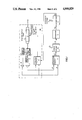
- FIG. 1 is a block diagram of the device for determining the moment of switching the system for active thermoregulation of the resonator length of a frequency stabilized laser
- FIG. 2 represents a time diagram of the signals at characteristic points of the device.
- the device for determining the moment of switching of the system for active thermoregulation of the resonator length of a frequency stabilized laser comprises a comparator 1, the output of which is connected with the control input of the unit 2 for active thermoregulation of the resonator of the frequency stabilized laser 12.
- the output of the comparator 1 is connected with the thermal element of the laser tube 3.
- the laser tube 3 is connected optically through the polarization light divider 4 with photoreceivers 5 and 6 in the two downstream branches of the splitter 4.
- the photoreceivers 5 and 6 are electrically connected through the amplifiers 7 and 8 with the unit 2 for active thermoregulation of the resonator of the frequency stabilized laser.
- the first input of comparator 1 is connected with the outputs of the photoreceivers 5 and 6 through the series connection of a differential amplifier 9, a signal shaper 10 and an integrator 11.
- the second input of comparator 1 is connected with the source of reference voltage G.
- the laser tube 3, the unit 2 for active thermoregulation of the laser resonator, the polarization light divider 4, the photoreceivers 5 and 6 and the amplifiers 7 and 8 form the system for active thermoregulation of the resonator length of the frequency stabilized laser 12.
- the operation of the device for determining of the moment of switching of the system for active thermoregulation of the resonator length of the frequency stabilized laser is as follows:
- the feeding of the laser tube 3 is switched on.
- the laser radiation emanating from the rear mirror of the laser resonator e.g. a He-Ne internal mirror laser
- the polarization light divider 4 is so tuned with respect to the laser tube 3 that the signals from the photoreceivers 5 and 6 correspond to the change in intensity of both polarizations of the laser radiation in changing the length of resonator of the laser tube 3 as a result of temperature deformations.
- the electric signals from photoreceivers 5 and 6 are periodic. The period increases proportionally to the decrease in rate of the thermal expansion of the resonator of the laser tube 3.
- the signals outputted by the photoreceivers are amplified by operational amplifiers 7 and 8 and are passed to both inputs of the differential amplifier 9.
- At the inputs of differential amplifier 9 enter signals A and B (FIG. 2) corresponding to the intensity of both polarizations of the laser radiation.
- the difference between the signals A and B is fed to the signal shaper 10 having a threshold D while the bipolar signal E that is formed there, is integrated by the integrator 11.
- the comparator 1 follows the level of output signal F (FIG. 2) of the integrator 11 and in reaching of preset level G of the reference voltage, it generates a signal H for switching of the unit 2 for active thermoregulation of the resonator of frequency stabilized laser 12 to commence active thermoregulation.
- F output signal
- G preset level G of the reference voltage
- H for switching of the unit 2 for active thermoregulation of the resonator of frequency stabilized laser 12 to commence active thermoregulation.
- laser 12 enters into a regime of regulating always at the same rate independently from the temperature of the ambient medium, air convection and the changes during entry into the regime. This rate is, in general, from 6 to 8 ⁇ /2 for min where ⁇ is the length of the wave of the laser tube 3 used.
Landscapes
- Physics & Mathematics (AREA)
- Electromagnetism (AREA)
- Engineering & Computer Science (AREA)
- Plasma & Fusion (AREA)
- Optics & Photonics (AREA)
- Lasers (AREA)
Applications Claiming Priority (2)
| Application Number | Priority Date | Filing Date | Title |
|---|---|---|---|
| BG82012 | 1987-11-30 | ||
| BG82012A BG47632A1 (en) | 1987-11-30 | 1987-11-30 | Method and device for determining moment of switching of system for active thermostabilizing of resonator lenght in frequency stabilized lasers |
Publications (1)
| Publication Number | Publication Date |
|---|---|
| US4908829A true US4908829A (en) | 1990-03-13 |
Family
ID=3919801
Family Applications (1)
| Application Number | Title | Priority Date | Filing Date |
|---|---|---|---|
| US07/276,212 Expired - Fee Related US4908829A (en) | 1987-11-30 | 1988-11-23 | Laser frequency stabilization by active resonator length regulation |
Country Status (7)
| Country | Link |
|---|---|
| US (1) | US4908829A (ja) |
| JP (1) | JPH02138783A (ja) |
| CN (1) | CN1035589A (ja) |
| BG (1) | BG47632A1 (ja) |
| DE (1) | DE3840255A1 (ja) |
| FR (1) | FR2623947B3 (ja) |
| GB (1) | GB2212973A (ja) |
Cited By (5)
| Publication number | Priority date | Publication date | Assignee | Title |
|---|---|---|---|---|
| US5392303A (en) * | 1993-03-30 | 1995-02-21 | Nec Corporation | Frequency stabilization method of semiconductor laser, frequency-stabilized light source and laser module |
| GB2331177A (en) * | 1997-11-10 | 1999-05-12 | Mitutoyo Corp | Wavelength stabilisation of a laser device |
| US5982794A (en) * | 1996-12-18 | 1999-11-09 | Ando Electric Co., Ltd. | External resonator type of variable-wavelength semiconductor laser light source |
| US6120190A (en) * | 1997-11-26 | 2000-09-19 | Lasertron, Inc. | Spatially variable bandpass filter monitoring and feedback control of laser wavelength especially in wavelength division multiplexing communication systems |
| US20080014965A1 (en) * | 1991-12-26 | 2008-01-17 | Emsat Advanced Geo-Location Technology, Llc | Cellular telephone system that uses position of a mobile unit to make call management decisions |
Families Citing this family (2)
| Publication number | Priority date | Publication date | Assignee | Title |
|---|---|---|---|---|
| CN106383346B (zh) * | 2016-09-14 | 2019-04-02 | 深圳天眼激光科技有限公司 | 脉冲激光扫描回波接收电路、接收方法及脉冲式激光扫描仪 |
| JP2019087550A (ja) * | 2017-11-01 | 2019-06-06 | 株式会社ミツトヨ | レーザ装置及びレーザ安定化方法 |
Citations (8)
| Publication number | Priority date | Publication date | Assignee | Title |
|---|---|---|---|---|
| US4571728A (en) * | 1982-04-09 | 1986-02-18 | Olympus Optical Co., Ltd. | Temperature control device for a semiconductor laser |
| US4573159A (en) * | 1983-07-15 | 1986-02-25 | Fuji Photo Film Co., Ltd. | Temperature-controlled laser apparatus |
| US4631728A (en) * | 1985-07-22 | 1986-12-23 | The United States Of America As Represented By The Secretary Of The Navy | Thermoelectric cooler control circuit |
| US4683573A (en) * | 1985-09-24 | 1987-07-28 | Bell Communications Research, Inc. | Temperature stabilization of injection lasers |
| US4689659A (en) * | 1985-02-18 | 1987-08-25 | Fuji Photo Film Co., Ltd. | Temperature controller for semiconductor device |
| US4701607A (en) * | 1985-04-15 | 1987-10-20 | Arel Control Systems, Ltd. | Temperature control laser detection apparatus |
| US4727554A (en) * | 1985-02-18 | 1988-02-23 | Fuji Photo Film Co., Ltd. | Temperature controller for semiconductor devices |
| US4834477A (en) * | 1984-07-05 | 1989-05-30 | Ricoh Company, Ltd. | Method of controlling the temperature of semiconductor laser in an optical device |
Family Cites Families (4)
| Publication number | Priority date | Publication date | Assignee | Title |
|---|---|---|---|---|
| DE3042666C2 (de) * | 1980-11-12 | 1985-10-10 | Moskovskoe vysšee techničeskoe učilišče imeni N.E. Baumana, Moskva | Laser-Spektrofon zum Analysieren von Gasen |
| DD203435A1 (de) * | 1982-02-01 | 1983-10-19 | Adw Ddr | Anordnung zur stabilisierung der resonatorlaenge modensynchronisierter gaslaser |
| GB8621037D0 (en) * | 1986-08-30 | 1986-10-08 | Renishaw Plc | Pre-heat control system |
| DE3706635A1 (de) * | 1987-03-02 | 1988-09-15 | Spindler & Hoyer Kg | Verfahren zur stabilisierung der frequenz einer laserdiode unabhaengig vom diodenstrom |
-
1987
- 1987-11-30 BG BG82012A patent/BG47632A1/xx unknown
-
1988
- 1988-11-23 US US07/276,212 patent/US4908829A/en not_active Expired - Fee Related
- 1988-11-25 FR FR888815454A patent/FR2623947B3/fr not_active Expired - Fee Related
- 1988-11-25 GB GB8827638A patent/GB2212973A/en not_active Withdrawn
- 1988-11-29 DE DE3840255A patent/DE3840255A1/de not_active Withdrawn
- 1988-11-30 CN CN88108201A patent/CN1035589A/zh active Pending
- 1988-11-30 JP JP63301104A patent/JPH02138783A/ja active Pending
Patent Citations (8)
| Publication number | Priority date | Publication date | Assignee | Title |
|---|---|---|---|---|
| US4571728A (en) * | 1982-04-09 | 1986-02-18 | Olympus Optical Co., Ltd. | Temperature control device for a semiconductor laser |
| US4573159A (en) * | 1983-07-15 | 1986-02-25 | Fuji Photo Film Co., Ltd. | Temperature-controlled laser apparatus |
| US4834477A (en) * | 1984-07-05 | 1989-05-30 | Ricoh Company, Ltd. | Method of controlling the temperature of semiconductor laser in an optical device |
| US4689659A (en) * | 1985-02-18 | 1987-08-25 | Fuji Photo Film Co., Ltd. | Temperature controller for semiconductor device |
| US4727554A (en) * | 1985-02-18 | 1988-02-23 | Fuji Photo Film Co., Ltd. | Temperature controller for semiconductor devices |
| US4701607A (en) * | 1985-04-15 | 1987-10-20 | Arel Control Systems, Ltd. | Temperature control laser detection apparatus |
| US4631728A (en) * | 1985-07-22 | 1986-12-23 | The United States Of America As Represented By The Secretary Of The Navy | Thermoelectric cooler control circuit |
| US4683573A (en) * | 1985-09-24 | 1987-07-28 | Bell Communications Research, Inc. | Temperature stabilization of injection lasers |
Non-Patent Citations (4)
| Title |
|---|
| Japanese Journal of Applied Physics, vol. 19, No. 11, Nov. 1980, pp. 2181 2185 Toshihiko Yoshino. * |
| Japanese Journal of Applied Physics, vol. 19, No. 11, Nov. 1980, pp. 2181-2185--Toshihiko Yoshino. |
| Unite Laser, Soro France Metrilas M. 100 E,ppl, 3,26 32. * |
| Unite Laser, Soro-France-Metrilas M. 100--E,ppl, 3,26-32. |
Cited By (6)
| Publication number | Priority date | Publication date | Assignee | Title |
|---|---|---|---|---|
| US20080014965A1 (en) * | 1991-12-26 | 2008-01-17 | Emsat Advanced Geo-Location Technology, Llc | Cellular telephone system that uses position of a mobile unit to make call management decisions |
| US5392303A (en) * | 1993-03-30 | 1995-02-21 | Nec Corporation | Frequency stabilization method of semiconductor laser, frequency-stabilized light source and laser module |
| US5982794A (en) * | 1996-12-18 | 1999-11-09 | Ando Electric Co., Ltd. | External resonator type of variable-wavelength semiconductor laser light source |
| GB2331177A (en) * | 1997-11-10 | 1999-05-12 | Mitutoyo Corp | Wavelength stabilisation of a laser device |
| GB2331177B (en) * | 1997-11-10 | 2002-05-15 | Mitutoyo Corp | Wavelength stabilizing device of laser device |
| US6120190A (en) * | 1997-11-26 | 2000-09-19 | Lasertron, Inc. | Spatially variable bandpass filter monitoring and feedback control of laser wavelength especially in wavelength division multiplexing communication systems |
Also Published As
| Publication number | Publication date |
|---|---|
| BG47632A1 (en) | 1990-08-15 |
| FR2623947A1 (fr) | 1989-06-02 |
| CN1035589A (zh) | 1989-09-13 |
| DE3840255A1 (de) | 1989-06-08 |
| FR2623947B3 (fr) | 1990-03-02 |
| JPH02138783A (ja) | 1990-05-28 |
| GB8827638D0 (en) | 1988-12-29 |
| GB2212973A (en) | 1989-08-02 |
Similar Documents
| Publication | Publication Date | Title |
|---|---|---|
| US5204867A (en) | Method and apparatus to dynamically control the resonator gain of a laser | |
| US4025875A (en) | Length controlled stabilized mode-lock Nd:YAG laser | |
| US5305334A (en) | Pulsed solid state ring laser injection locking stabilizer | |
| US20050162662A1 (en) | Method and device for measuring wall thickness of a pipe in a pipe-rolling mill | |
| US4908829A (en) | Laser frequency stabilization by active resonator length regulation | |
| US5383209A (en) | Second harmonic generator | |
| WO1990001226A1 (en) | Laser frequency control | |
| EP0196856A2 (en) | Dual-wavelength laser apparatus | |
| US5347124A (en) | Control system for oscillatory-mirror light beam deflector | |
| CA1045234A (en) | Laser amplifier system | |
| JP2644315B2 (ja) | 高周波放電励起レーザ装置 | |
| US5943353A (en) | Laser light source apparatus | |
| US5926495A (en) | Laser diode pump wavelength sensing and control apparatus and method | |
| GB1320967A (en) | Laser system comprising means for controlling the frequency of a laser beam | |
| US4949345A (en) | Method and apparatus for reducing the effect of random polarization on the power/energy output of lasers | |
| US4866722A (en) | Metal vapor laser device stabilizing system | |
| JP2511721B2 (ja) | マルチモ―ドラマンレ―ザ―システム | |
| JPH0416031B2 (ja) | ||
| JPH09246646A (ja) | 半導体レーザ制御装置 | |
| US20070147446A1 (en) | Frequency stabilised gas laser | |
| US4866721A (en) | Pulsed laser stabilizing device | |
| KR950002067B1 (ko) | 제2고조파 발생장치 | |
| JP2746227B2 (ja) | イオンレーザ装置 | |
| JPH1022559A (ja) | 高調波発生装置の制御方法及び高調波発生装置 | |
| JP3465048B2 (ja) | 光増幅方法、光増幅装置、及び光増幅用光共振器 |
Legal Events
| Date | Code | Title | Description |
|---|---|---|---|
| AS | Assignment |
Owner name: SU KLIMENT OHRIDSKI , 1000 SOFIA, BOUL. RUSKI 15, Free format text: ASSIGNMENT OF ASSIGNORS INTEREST.;ASSIGNORS:KRUGLII, VASSIL P.;SHURULINKOV, STANISLAV P.;REEL/FRAME:004971/0390 Effective date: 19881111 Owner name: SU KLIMENT OHRIDSKI, BULGARIA Free format text: ASSIGNMENT OF ASSIGNORS INTEREST;ASSIGNORS:KRUGLII, VASSIL P.;SHURULINKOV, STANISLAV P.;REEL/FRAME:004971/0390 Effective date: 19881111 |
|
| REMI | Maintenance fee reminder mailed | ||
| LAPS | Lapse for failure to pay maintenance fees | ||
| FP | Expired due to failure to pay maintenance fee |
Effective date: 19940313 |
|
| STCH | Information on status: patent discontinuation |
Free format text: PATENT EXPIRED DUE TO NONPAYMENT OF MAINTENANCE FEES UNDER 37 CFR 1.362 |