US4903983A - Actively controlled automotive suspension system with improved cornering characteristics - Google Patents
Actively controlled automotive suspension system with improved cornering characteristics Download PDFInfo
- Publication number
- US4903983A US4903983A US07/052,934 US5293487A US4903983A US 4903983 A US4903983 A US 4903983A US 5293487 A US5293487 A US 5293487A US 4903983 A US4903983 A US 4903983A
- Authority
- US
- United States
- Prior art keywords
- vehicle
- suspension
- sensor
- wheels
- load distribution
- Prior art date
- Legal status (The legal status is an assumption and is not a legal conclusion. Google has not performed a legal analysis and makes no representation as to the accuracy of the status listed.)
- Expired - Fee Related
Links
Images


Classifications
-
- B—PERFORMING OPERATIONS; TRANSPORTING
- B60—VEHICLES IN GENERAL
- B60G—VEHICLE SUSPENSION ARRANGEMENTS
- B60G17/00—Resilient suspensions having means for adjusting the spring or vibration-damper characteristics, for regulating the distance between a supporting surface and a sprung part of vehicle or for locking suspension during use to meet varying vehicular or surface conditions, e.g. due to speed or load
- B60G17/015—Resilient suspensions having means for adjusting the spring or vibration-damper characteristics, for regulating the distance between a supporting surface and a sprung part of vehicle or for locking suspension during use to meet varying vehicular or surface conditions, e.g. due to speed or load the regulating means comprising electric or electronic elements
- B60G17/016—Resilient suspensions having means for adjusting the spring or vibration-damper characteristics, for regulating the distance between a supporting surface and a sprung part of vehicle or for locking suspension during use to meet varying vehicular or surface conditions, e.g. due to speed or load the regulating means comprising electric or electronic elements characterised by their responsiveness, when the vehicle is travelling, to specific motion, a specific condition, or driver input
- B60G17/0162—Resilient suspensions having means for adjusting the spring or vibration-damper characteristics, for regulating the distance between a supporting surface and a sprung part of vehicle or for locking suspension during use to meet varying vehicular or surface conditions, e.g. due to speed or load the regulating means comprising electric or electronic elements characterised by their responsiveness, when the vehicle is travelling, to specific motion, a specific condition, or driver input mainly during a motion involving steering operation, e.g. cornering, overtaking
Definitions
- the present invention relates generally to a suspension system for a vehicle. More specifically, the invention relates to an automotive suspension system with improved cornering characteristics. Further particularly, the invention relates to a control system for an automotive suspension system, which actively controls load distribution at respective vehicular wheels for better cornering characteristics.
- a typical construction of a suspension assembly comprises a suspension coil and shock absorber and is interposed between a vehicle body and a suspension member supporting a vehicular wheel, in order to constitute an automotive suspension system with the suspension member.
- the suspension coil spring generally resists against lad applied to maintain the vehicle body and the road wheel in a predetermined positional relationship to each other.
- the shock absorber is intended to damp or absorb vibrations transmitted between the vehicle body and the road wheel.
- the automotive suspension system may be further provided with a roll-stabilizer for suppressing vehicular rolling motion.
- Some of the many kinds of automotive suspension systems include hydraulic circuits associated with fluid chambers in hydraulic shock absorbers for the controlling balance between the fluid pressures in the fluid chambers according to the relative displacement between the vehicle body and road wheel.
- Such hydraulic circuits include a fluid pressure source supplying working fluid at a given pressure to the circuits, and pressure control valves.
- the pressure control valves hydraulically connect and disconnect the fluid pressure source with the fluid chambers of the hydraulic shock absorbers for controlling pressure supply.
- the pressure control valves are controlled by an electric or electronic control system which switches the various valve positions to selectively introduce or drain fluid pressure into or from the fluid chambers so as to generate a damping force which suppresses vehicle body and road wheel vibrations.
- an object of the present invention to provide an automotive suspension system which has a hydraulic damping force control circuit capable of effectively suppressing vehicle vibrations, thus ensuring riding comfort.
- the proposed positively controlled automotive suspension system comprises a hollow cylinder defining a chamber, a piston thrustingly received within the chamber of the cylinder and defining therein a first and second fluid chambers, both filled with a working fluid, the piston being free to move axially with the chamber, a fluid pressure source, a hydraulic circuit connecting the first and second fluid chambers and the fluid pressure source, a pressure control valve disposed within the hydraulic circuit and adapted to selectively establish and block fluid communication between the first and second fluid chambers and the fluid pressure source, means responsive to relative displacement between a vehicle body and road wheel assembly out of a predetermined normal range, for controlling the pressure control valve so as to adjust the fluid pressure in the first and second fluid chambers in order to adjust the relative distance between the vehicle body and the road wheel assembly back to within the predetermined normal range, and means responsive to bounding and
- cornering force is the counter force against the combined longitudinal and lateral forces as set forth.
- the magnitude of this counter force to be generated is determined by road/tire friction.
- the magnitude of the road/tire friction is variable depending upon the load applied to the road wheel. Therefore, the combination of the combined force and the counter force at each vehicular wheel will determine the cornering characteristics of the vehicle.
- the maximum counter force to be generated at each wheel is determined by road/tire friction.
- the distribution of the friction magnitude at the respective road wheel is variable depending upon the shift of a gravity center during cornering due to the change of load distribution.
- the tire loses traction to cause a lateral slide to increase over-steer characteristics.
- under-steer characteristics may increase according to increasing driving torque as the longitudinal force. This prevents the vehicle from handling the corner at high speed. Therefore, in order to optimize cornering characteristics of the vehicle at relatively high speed, balance of the combined force of the longitudinal and lateral forces and the counter force is required.
- high driving techniques such as delicate accelerator pedal control and steering operation synchronized with accelerator pedal control is required.
- Another object of the invention is to provide an automotive suspension system with variable stiffness, which stiffness is controlled to permit a desired magnitude of tail-slide in cornering to allow high speed cornering, automatically.
- a suspension system for an automotive vehicle employs an active suspension control feature for actively controlling the suspension characteristics according to the vehicle driving conditions.
- Active suspension control is performed by adjusting offset of a gravity center for adjusting load distribution at respective vehicular wheels.
- the load distribution is adjusted so that the suspension characteristics can be changed to over-steer characteristics when the vehicle speed demand is higher than a given level so as to allow drift of the vehicle at a corner.
- the suspension system in order to assure driving stability, is further adjusted to suppress vehicular rolling during drift of the vehicle.
- a suspension system for an automotive vehicle comprises damper assemblies disposed between a vehicle body and a plurality of suspension members which support respectively associated road wheels, each of the damper assemblies including hydraulic means having adjustable hydraulic pressure, a hydraulic circuit connected to the hydraulic means for supplying pressurized working fluid thereto, sensor means for monitoring predetermined vehicle driving conditions indicating parameters to produce a driving condition indicating sensor signal, and a controller responsive to the driving condition indicating sensor signal to derive a load distribution at respective road wheels, the controller producing pressure control signals for the respective hydraulic means to cause a change of hydraulic pressure in each damper assembly to cause an offset of the gravity center of the vehicle body at a controlled magnitude and controlled direction to obtain derived load distribution for desired optimum vehicle driving characteristics.
- the sensor means includes means for monitoring vehicular speed demand indicating parameters to produce a vehicular speed indicating sensor signal, and the controller responsive to the vehicular speed demand indicating sensor signal to derive a load distribution coefficient on which the load distribution is derived.
- the load distribution coefficient defines load distribution between front road wheels and rear road wheels.
- the hydraulic means comprises a hydraulic cylinder having disposed therein a reciprocating piston which defines a fluid chamber within the hydraulic cylinder and responsive to the hydraulic pressure within the fluid chamber, and a valve means interposed between the hydraulic circuit and the fluid chamber for supplying and draining pressurized working fluid to and from the fluid chamber for adjusting fluid pressure in the fluid chamber according to the pressure control signal.
- the pressure control valve includes a valve body and an electrically operable actuator for shifting the valve body for adjusting fluid pressure in the fluid chamber according to the pressure control signal.
- the sensor means may include means for monitoring lateral force exerted on the vehicle for producing a lateral force indicating signal and means for monitoring vehicular speed demand indicating parameters to produce a vehicular speed indicating sensor signal, and the controller responsive to the lateral force indicating signal and vehicular speed demand indicating sensor signal to derive a load distribution coefficient on which the load distribution is derived.
- the controller is responsive to vehicular speed demand indicating parameter having a value greater than a predetermined value to change vehicular steering characteristics to over-steer characteristics.
- a suspension control system for providing optimum cornering characteristics with increased cornering speed, comprises suspension systems provided for respective road wheels for producing damping forces against vertically exerted forces, each suspension system including means for adjusting damping characteristics thereof, a first sensor for detecting vehicular driving speed demand in excess of a predetermined value to produce a first sensor signal, a second sensor for detecting the vehicular steering condition at a corner to produce a second sensor signal, a controller responsive to the first and second sensor signals for deriving suspension control signals for controlling the damping characteristic adjusting means in order to adjust stiffness of respective suspension systems for adjusting load distribution at respective wheels for obtaining optimum cornering characteristics of the vehicle.
- the controller is responsive to the first sensor signal and the second sensor signal to adjust stiffness of respective suspension systems so that cornering force at the rear wheels is decreased to provide over-steer characteristics of the vehicle.
- the controller stiffens suspension systems for wheels located remote from the center of the corner and softens suspension systems for wheels located close to the center for suppressing vehicular rolling in order to assure traction at the respective wheels.
- a suspension control system for providing optimum cornering characteristics with increased cornering speed, comprises suspension systems provided for respective road wheels for producing damping forces against vertically exerted forces, each suspension system including means for adjusting damping characteristics thereof, a first sensor for detecting vehicular driving speed demand to produce a first sensor signal indicative thereof, a second sensor for detecting vehicular steering condition to produce a second sensor signal indicative thereof, and a controller responsive to the first and second sensor signals for detecting vehicle driving conditions on the basis thereof and deriving suspension control signals for controlling the damping characteristic adjusting means in order to adjust stiffness of respective suspension systems for adjusting load distribution at respective wheels for obtaining optimum cornering characteristics of the vehicle, the controller responsive to the first sensor signal value greater than a given value to adjust stiffness of respective suspension systems so that the cornering force at rear wheels is decreased to provide over-steer characteristics of the vehicle.
- FIG. 1 is a diagrammatical illustration showing the overall construction of the preferred embodiment of an automotive suspension system with a control system actively controlling the suspension system according to the present invention
- FIG. 2 is a section of one example of a hydraulic shock absorber in combination with a hydraulic pressure control valve associated with the shock absorber for adjusting stiffness of the latter;
- FIG. 3 is a block diagram of the suspension control system in the actively controlled automotive suspension system of FIG. 1;
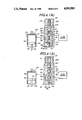
- FIGS. 4(A) and 4(B) are enlarged sections showing the detail of the hydraulic pressure control valve of FIG. 3, in which, FIG. 4(A) shows the valve position softening the shock absorber and FIG. 4(B) shows the valve position hardening the shock absorber;
- FIG. 5 is a graph showing variation of hydraulic pressure to be supplied to a pressure control valve according to variation of drive signal voltage
- FIG. 6 is an explanatory illustration showing the forces to be exerted on a road wheel during cornering
- FIG. 7 is a graph showing the variation of cornering force according to shifting of the gravity center or variation of the load applied to road wheels.
- FIG. 8 is an illustration of the variation of attitude of the vehicle during cornering at high speed.
- a vehicle has four suspension systems 11FL, 11FR, 11RL and 11RR for respectively suspending vehicle body 12 on front-left, front-right, rear-left and rear-right road wheels 14FL, 14FR, 14RL and 14RR.
- Each of the front-left, front-right, rear-left and rear-right suspension systems 11FL, 11FR, 11RL and 11RR comprises a suspension member 13, such as a suspension link, a suspension arm and so forth, and a suspension assembly 15 which is interposed between the vehicle body 12 and the suspension member 13.
- the suspension assembly 15 has a hydraulic cylinder 15A which serves as an actuator, and a coil spring 16.
- the hydraulic cylinder 15A has a hollow cylinder housing 15a filled with a viscous working fluid and a piston 15b sealingly and thrustingly disposed within the internal space of the cylinder housing to divide the cylinder space into upper and lower fluid chambers 15d and 15e.
- a piston rod 15c extends through one end of the cylinder housing 15a.
- the other end of the cylinder housing 15a is connected to one of the vehicle body 12 and the suspension member 13.
- the end of the piston rod 15c is connected to the other end of the vehicle body 12 and the suspension member 13.
- the hydraulic cylinder 15A of the suspension assembly 15 is connected to a hydraulic pressure source unit 20 via a hydraulic circuit which includes pressure control valve 18.
- the pressure control valve 18 is electrically operable and connected to a control unit 30.
- the hydraulic circuit 19 includes a supply line 19s and a drain line 19d. High pressure accumulators 22f and 22r are connected to the supply line 19s and a low pressure accumulator 23f and 23r are connected to the drain line 19d.
- the pressure source unit comprises a pressure unit 20 and a reservoir tank 21.
- the pressure unit 20 is connected to the reservoir tank 21 to suck the viscous working fluid in the reservoir tank 21 to feed to the pressure control valve 18 via the supply line 19s.
- the drain line 19d is connected to the reservoir 21 to return the working fluid thereto.
- the controller 30 is connected to stroke sensors 17 which are respectively interposed between the vehicle body 12 and the corresponding suspension members 13.
- Each stroke sensor comprises a potentiometer, for example, and is designed to monitor the relative distance between the vehicle body 12 and the associated suspension member 13 to produce a stroke indicating signal.
- the stroke indicating signal varies with the signal value to indicate the magnitude of relative displacement of the vehicle body 12 and the suspension member 13 from the neutral position. Namely, when the relative distance expands, the stroke indicating signal value becomes positive and increases as does the expanded magnitude, and when the relative distance decreases from the neutral position, the stroke indicating signal value decreases as does the relative distance.
- the controller 30 is also connected to a lateral acceleration sensor 24, a transmission gear position sensor 25 and a throttle angle sensor 26.
- the lateral acceleration sensor 24 monitors acceleration laterally exerted on the vehicle to produce a lateral acceleration indicating signal ⁇ .
- the lateral acceleration indicating signal value ⁇ has a voltage variable depending upon the magnitude and direction of the lateral acceleration. In the illustrated embodiment, the positive voltage of the lateral acceleration indicating signal increases with the leftward lateral acceleration, and the negative voltage decreases as rightward lateral acceleration increases.
- the transmission gear position sensor 25 is associated with an automotive power transmission to detect the shift position of the transmission to produce a transmission gear position indicating signal g.
- the transmission gear position indicating signal has a voltage variable depending upon the transmission gear position.
- the throttle angle sensor 26 monitors the angular position of a throttle valve (not shown) linked with an accelerator pedal (not shown) in per se well known manner, to produce a throttle angle indicating signal ⁇ .
- the transmission gear position sensor 24 and the throttle angle sensor 26 constitute a vehicle driving condition indicating parameter detecting means.
- the lateral acceleration sensor 24 constitutes a vehicle running condition indicating parameter detecting means.
- the controller 30 receives the aforementioned stroke indicating signals from the stroke sensors 17, a lateral acceleration indicating signal ⁇ from the lateral acceleration sensor 24, the transmission gear position indicating signal g from the transmission gear position sensor 25 and the throttle angle indicating signal ⁇ of the throttle angle sensor 26 to derive a control signal based thereon.
- the controller 30 outputs the control signal to the pressure control valves 18.
- FIG. 2 shows the detailed construction of the hydraulic cylinder 15A and the pressure control valve 18.
- the hollow cylinder housing 15a is formed with a port 15f communicating the upper fluid chamber 15d to an outlet port 18d of the pressure control valve 18 via a communication line 27.
- the pressure control valve 18 has a valve housing 18A having the aforementioned outlet port 18d, an inlet port 18b and a drain port 18c. Respective inlet port 18b, the drain port 18c and the outlet port 18d are connected to a valve bore 18a defined within the valve housing 18A.
- a valve spool 19 is disposed within the valve bore 18a for thrusting movement therein.
- the valve spool 19 has first, second and third lands, 19a, 19b and 19c.
- the third land 19c has smaller diameter than that of the first and second lands 19a and 19b.
- the third land 19c defines a fifth pressure control chamber 18h which is connected to the drain port 18c via a drain path 18f.
- An actuation rod 29 is also disposed within the valve bore 18a.
- the actuation rod 20 opposes the second land 19b in spaced apart relationship to define a second pressure control chamber 18i which is connected to the drain port 18c via a drain path 18e.
- An annular pressure chamber 18j is defined between the first and second lands 19a and 19b. The pressure chamber 18j is constantly communicated with the outlet port 18d and thereby communicated with the upper fluid chamber 15d.
- the pressure chamber 18j shifts according to shifting of the valve spool 19 to selectively communicate with the inlet port 18b and the drain port 18c.
- annular pressure control chamber 18k is defined between the first and third lands 19a and 19c.
- the pressure control chamber 18k is in communication with the outlet port 18d via a pilot path 18g.
- a bias spring 21 is interposed between the actuation rod 20 and the valve spool 19.
- the actuation rod 20 contacts an actuator rod 22a of an electrically operable actuator 22 which comprises an electromagnetic solenoid.
- the solenoid 22 comprises a proportional solenoid.
- FIG. 3 shows the controller 30 in the form of a block diagram.
- the controller 30 generally comprises a first driving parameter indicating value generator 31, a second driving parameter indicating gain constant generating circuit 32, multipliers 33, 34f and 34r, inverters 35f and 35r, and comparators 36FL, 36FR, 36RL and 36RR.
- the first driving parameter indicating value generator circuit 31 derives a first driving parameter indicating value.
- the first driving parameter indicating value generator circuit 31 receives the transmission gear position indicating signal g from the transmission gear position sensor 25.
- the first driving parameter indicating value generator 31 derives a reciprocal of the gear ratio corresponding to the transmission gear position as represented by the transmission gear position indicating signal.
- the first driving parameter indicating value generator comprises a plurality of value generators, each of which is designed to produce a value corresponding to the reciprocal of the gear ratio at the corresponding transmission gear position.
- one of the value generators which corresponds to one of the transmission gear positions as indicated in the transmission gear position indicating signal, is triggered to output a first driving value indicating signal N.
- the first driving coefficient indicating signal N is fed to the multiplier 33.
- the multiplier 33 also receives the throttle angle indicating signal T from the throttle angle sensor 26.
- the multiplier 33 multiples the first value indicating signal N with the throttle angle indicating signal ⁇ to derive an assumed driving force indicating value T.
- the assumed driving force indicating value T is fed to the driving parameter indicating gain constant generating circuit 32.
- the driving parameter indicating gain constant generating circuit 32 derives a gain constant based on the second driving parameter indicating value T.
- the driving parameter indicating gain constant generating circuit 32 has a gain constant data table which is in the form of a look-up table.
- the gain contact data table is looked up in terms of the assumed driving force T.
- the gain contact K 1 for the front wheels 14FL and 14FR gradually decreases according to increasing of the assumed driving force T.
- the gain constant K 1 for the front wheels 14FL and 14FR is hereafter referred to as "front gain constant”.
- the gain constant K 2 for the rear wheels 14RL and 14RR increases according to increasing of the assumed driving force T.
- the gain constant K 2 for the rear wheels 14RL and 14RR is hereafter referred to as "rear gain constant".
- the front gain constant K 1 is greater than the rear gain constant K 2 .
- the difference between the front and rear gain constants K 1 and K 2 decreases as the assumed driving force increases.
- the rear gain constant K 2 increases across the front gain constant K 1 at a given assumed driving force.
- the driving parameter indicating gain constant generating circuit 32 outputs a front gain indicating signal representative of the front gain constant to the multiplier 34f and a rear gain indicating signal representative of the rear gain constant to the multiplier 34r.
- the multipliers 34f and 34r are connected to the lateral acceleration sensor 24 to receive therefrom a lateral acceleration indicating signal having a lateral acceleration indicating value ⁇ .
- the lateral acceleration indication value ⁇ of the lateral acceleration indicating signal is multiplied by the front and rear gain constants K 1 and K 2 respectively in the multipliers 34f and 34r.
- the multiplier 34f thus derives a magnitude of a shift of load between the front wheels 14FL and 14FR on the basis of the front gain constant K 1 as a front driving condition indicating variable, and the lateral acceleration.
- the value derived by the multiplier 34f is thus indicative of the magnitude of shifting of the load at respective front-left and front-right wheels and, in turn, indicative of the magnitude of variation of the relative distance between the vehicle body and the suspension member. Therefore, the multiplier outputs a front target stroke signal Wf indicative of the derived magnitude of the load shift between the front wheels.
- the multiplier 34r derives a magnitude of a shift of load between rear wheels 14RL and 14RR.
- the value derived by the multiplier 34r is thus indicative of the magnitude of shifting of the load at respective rear-left and rear-right wheels and, in turn, indicative of the magnitude of variation of the relative distance between the vehicle body and the suspension member. Therefore, the multiplier outputs a rear target stroke signal Wr having a value representative of the rear load shifting magnitude.
- the multiplier 34f feeds the front load shift control signal Wf to a comparator 36FL for the front-left wheel and to a comparator 36FR via an inverter 35f. Therefore, the polarity of the front load shift control signals 36FL and 36FR becomes alternative.
- the multiplier 34r feeds the rear load shift control signal Wr to a comparator 36RL for the front-left wheel and to a comparator 36RR via an inverter 35r. Therefore, the polarity of the front load shift control signals Wr to be applied to the comparators 36RL and 36RR becomes alternative.
- Each comparator 36FL, 36FR, 36RL and 36RR is connected to the stroke sensor 17 to receive the stroke indicating signal DS FL , DS FR , DS RL and DS RR .
- the comparators 36FL, 36RL and 36RR respectively, compare the control signals Wf, -Wf, Wr and -Wr with respective stroke indicating signals DS FL , DS FR , DS RL and DS RR in order to derive error indicating signals ⁇ FL , ⁇ FR , ⁇ RL and ⁇ RR .
- the error indicating signals ⁇ FL , ⁇ FR , ⁇ RL and ⁇ RR are representative of the magnitude of variation of the stroke of the hydraulic cylinders 15 at respective front-left, front-right, rear-left and rear-right wheels 14FL, 14FR, 14RL and 14RR.
- the comparators 36FL, 36FR, 36RL and 36RR feed the error indicating signals ⁇ FL , ⁇ FR , ⁇ RL and ⁇ RR to respectively associated driver circuits 37FL, 37FR, 37RL and 37RR.
- the driver circuits produce drive signals for respectively associated actuators 22 of the pressure control valves 18.
- the actuators 22 are thus actuated at the magnitudes respectively corresponding to the error values indicated by the effort indicating signal ⁇ FL , ⁇ FR , ⁇ RL and ⁇ RR , in order to reduce the error to zero.
- the input from the lateral acceleration sensor 24 is maintained at zero as long as the vehicle travels substantially straight and thus substantially no lateral force is exerted on the vehicle.
- the output as the front and rear target stroke indicating signals, of the multipliers 34f and 34r becomes substantially zero.
- the relative distances between the vehicle body and the suspension members are maintained substantially at the neutral position, since no lateral force is applied. Therefore, the values of the stroke indicating signals DS FL , DS FR , DS RL and DS RR to be inputted to the comparators 36FL, 36FR, 36RL and 36RR from respectively corresponding stroke sensors 17 are held substantially at zero.
- the output value of the comparators 36FL, 36FR, 36RL and 36RR are held at zero. Therefore, the error indicating signals ⁇ FL , ⁇ FR , ⁇ RL and ⁇ RR output from the comparators 36FL, 36FR, 36RL and 36RR are held substantially at zero. As a result, the driver circuit 37FL, 37FR, 37RL and 37RR are held inoperative to maintain the actuators 22 of respective pressure control valves 18 in place.
- steering operation may cause vehicular rolling to cause variation of the relative distances between the vehicle body and suspension members at the positions of the front-left, front-right, rear-left and rear-right wheels. Therefore, the stroke indicating signal value varies from zero.
- the stroke indicating signal values from the stroke sensors 17 associated with the front-left and rear-left wheels become positive and the stroke indicating signal values from the stroke sensors 17 associated with the front-right and rear-right wheels become negative.
- the lateral acceleration indicating signal values from the lateral acceleration sensor 24 become a negative value (- ⁇ ). Therefore, the front and rear target strokes Wf and Wr become negative.
- the negative value of the front target stroke (-Wf) is input to the comparator 36FL to be compared with the positive value of the stroke indicating signal DS FL . Therefore, the error indicating signal ⁇ FL indicative of the difference of the front target stroke indicating signal and the stroke indicating signal to reduce magnitude of rising cause a downward shift across the neutral position at the front-left wheel toward the front target stroke (-Wf).
- the inverted front target stroke (+Wf) is input to the comparator 36FR.
- the comparator 36FR also receives the negative value of the stroke indicating signal from the stroke sensor 17 associated with the front-right wheel.
- the error indicating signal ⁇ FR will be derived to adjust the relative distance between the vehicle body and the front-right suspension member toward the inverted front target stroke (+Wf).
- the negative value of the rear target stroke (-Wr) is input to the comparator 36RL to be compared with the positive value of the stroke indicating signal DSRL. Therefore, the error indicating signal ⁇ RL indicative of the difference of the rear target stroke indicating signal and the stroke indicating signal to reduce the magnitude of rising cause a downward shift down across the neutral position at the front-left wheel toward the rear target stroke (-Wr).
- the inverted rear target stroke (+Wr) is input to the comparator 36FR.
- the comparator 36FR also receives the negative value of the stroke indicating signal from the stroke sensor 17 associated with the rear-right wheel. As a result, the error indicating signal ⁇ RR will be derived to adjust the relative distance between the vehicle body and the rear-right suspension member toward the inverted rear target stroke (+Wr).
- the driver circuits 37FL, 37FR, 37RL and 37RR output drive signals to the respectively associated actuators 22.
- the driver signal value is variable to control the position of the valve spool 19.
- the pressure control valve 18 is designed to supply the working fluid pressure P 0 (shown in FIG. 5) to the upper fluid chamber 15d. As will be seen from FIG. 5, the working fluid pressure to be supplied to the upper fluid chamber 15d increases with the drive signal voltage V and decreases with the drive signal voltage.
- the spool valve 19 In order to increase the supply pressure of the working fluid the spool valve 19 is shifted to the position shown in FIG. 4(A) to increase path area at a throttle constituted at the inner end of the inlet port 18b by means of the land 19a of the spool valve 19. On the other hand, in order to decrease the supply pressure of the working fluid, the spool valve is shifted to the position shown in FIG. 4(B) to decrease the path area at the throttle of the inner end of the inlet port 18b and opens the drain port 18 which is normally blocked by means of the land 19b of the spool valve.
- Construction of the pressure control valves should not be limited to the construction as illustrated in FIGS. 2, 4(A) and 4(B) but can be replaced with any appropriate constructions.
- the pressure control valve constructions as illustrated in European Patent First Publication No. 01 93 124, set forth above, can also be employed.
- the disclosure of the aforementioned European Patent First Publication 01 93 124 is herein incorporated by reference for the sake of disclosure.
- cornering force F which is the combined force of a lateral counter force S and the driving torque T, as the counter force against the combined force of the centrifugal force and the driving torque as set forth, is generated.
- the magnitude of this counter force F to be generated is determined by road/tire friction, the magnitude of which is illustrated by a circle in FIG. 5 for the purpose of illustration.
- the magnitude of the road/tire friction is variable depending upon the load W applied to the road wheel. Therefore, the combination of the combined force and the counter force thereagainst at each vehicular wheel will determine the cornering characteristics of the vehicle.
- the maximum counter force Fmax to be generated at each wheel is determined by road/tire friction.
- the loads at the left and right wheels are respectively W L and W R
- the average load of the left and right wheel loads W L and W R is W 0
- a magnitude of shift of the load between the left and right wheels with respect to the center thereof is ⁇ W
- the maximum counter force Fmax decreases according to air increase of the load shift magnitude ⁇ W.
- the distribution of the friction magnitude at the respective road wheel is variable depending upon the shift of a gravity center during cornering due to the resulting change of load distribution.
- the rolling direction of the vehicle is reversed from the normal rolling direction. This changes the steering characteristics of the vehicle to be inclined toward over-steer characteristics. Therefore, as shown in FIG. 6, when the vehicle travels along a corner with a relatively high driving force, the vehicular suspension characteristics change toward the over-steer characteristics to cause tail-slide to drift without requiring any attention and/or skill of the driver.
Landscapes
- Engineering & Computer Science (AREA)
- Mechanical Engineering (AREA)
- Vehicle Body Suspensions (AREA)
Applications Claiming Priority (2)
| Application Number | Priority Date | Filing Date | Title |
|---|---|---|---|
| JP61-118675 | 1986-05-23 | ||
| JP61118675A JPH0741783B2 (ja) | 1986-05-23 | 1986-05-23 | サスペンシヨン制御装置 |
Publications (1)
| Publication Number | Publication Date |
|---|---|
| US4903983A true US4903983A (en) | 1990-02-27 |
Family
ID=14742420
Family Applications (1)
| Application Number | Title | Priority Date | Filing Date |
|---|---|---|---|
| US07/052,934 Expired - Fee Related US4903983A (en) | 1986-05-23 | 1987-05-22 | Actively controlled automotive suspension system with improved cornering characteristics |
Country Status (4)
| Country | Link |
|---|---|
| US (1) | US4903983A (de) |
| EP (1) | EP0246655B1 (de) |
| JP (1) | JPH0741783B2 (de) |
| DE (1) | DE3778419D1 (de) |
Cited By (56)
| Publication number | Priority date | Publication date | Assignee | Title |
|---|---|---|---|---|
| US5020446A (en) * | 1988-11-17 | 1991-06-04 | Bergische Stahl-Industrie | Three-dimensional single-wheel suspension for wheels of railed vehicles |
| US5027302A (en) * | 1988-08-10 | 1991-06-25 | Honda Giken Kogyo Kabushiki Kaisha | Device for switching vehicle operating characteristics |
| US5048861A (en) * | 1989-03-27 | 1991-09-17 | Nissan Motor Company, Limited | Active suspension system and pressure control valve therefor |
| US5054808A (en) * | 1989-04-27 | 1991-10-08 | Nissan Motor Company, Limited | Working fluid circuit for active suspension system with surge suppressive feature |
| US5062660A (en) * | 1989-04-28 | 1991-11-05 | Nissan Motor Company, Limited | Pressure medium fluid circuit for active suspension system with variable fluid source discharge rate depending upon magnitude of stroke in relative displacement between vehicular body and suspension member |
| US5074569A (en) * | 1989-04-20 | 1991-12-24 | Nissan Motor Company, Limited | Height control in active suspension system |
| US5076606A (en) * | 1989-03-27 | 1991-12-31 | Nissan Motor Company, Limited | Active suspension system with hydraulic circuit having line pressure dependent flow restriction for working fluid introduced into and drained from working chamber |
| US5083811A (en) * | 1989-04-28 | 1992-01-28 | Nissan Motor Company, Limited | Fluid supply circuit for active suspension system with variable fluid source discharge rate depending upon magnitude of lateral acceleration |
| US5085459A (en) * | 1989-03-30 | 1992-02-04 | Nissan Motor Company, Limited | Pressure supply network for active suspension system and control therefor |
| US5088762A (en) * | 1989-09-29 | 1992-02-18 | Nissan Motor Company, Limited | Control system for active suspension which distributes load according to lateral acceleration |
| US5092625A (en) * | 1989-04-20 | 1992-03-03 | Nissan Motor Company, Limited | Fail detecting system for electromagnetic actuator and fail-safe system for active suspension system incorporating electromagnetic actuator |
| US5103396A (en) * | 1989-05-15 | 1992-04-07 | Fuji Jukogyo Kabushiki Kaisha | System for controlling active suspensions of a vehicle |
| US5105358A (en) * | 1989-04-20 | 1992-04-14 | Nissan Motor Company, Limited | Active suspension system with enhanced system start-up activity |
| US5150917A (en) * | 1990-05-31 | 1992-09-29 | Nissan Motor Company, Limited | Active suspension system with control to change variation in pressure of working fluid cylinder between increase and decrease thereof |
| US5156645A (en) * | 1989-04-27 | 1992-10-20 | Nisson Motor Company, Limited | Working fluid circuit for active suspension system with surge suppression during fail-safe mode operation |
| US5159555A (en) * | 1989-04-22 | 1992-10-27 | Mitsubishi Denki K.K. | Control apparatus for support unit of vehicle |
| US5159554A (en) * | 1987-07-06 | 1992-10-27 | Toyota Jidosha Kabushiki Kaisha | Electronic controlled fluid suspension system |
| US5183127A (en) * | 1989-09-13 | 1993-02-02 | Mazda Motor Corporation | Suspension-traction total control system |
| US5218545A (en) * | 1989-12-05 | 1993-06-08 | Mazda Motor Corporation | Suspension apparatus of automotive vehicle with control system having a variable time constant |
| US5291406A (en) * | 1989-05-04 | 1994-03-01 | Group Lotus Plc | Land vehicle suspension control system |
| US5338058A (en) * | 1991-09-25 | 1994-08-16 | Mitsubishi Denki Kabushiki Kaisha | Damping force control system for vehicle suspension |
| US5383124A (en) * | 1989-05-20 | 1995-01-17 | Robert Bosch Gmbh | Process for undercarriage regulation |
| US5852787A (en) * | 1996-09-03 | 1998-12-22 | Ford Global Technologies, Inc. | Vehicle suspension control |
| WO2000010823A1 (en) | 1998-08-22 | 2000-03-02 | Land Rover Group Limited | Vehicle suspensions |
| US6076027A (en) * | 1998-02-03 | 2000-06-13 | Raad; Joseph Michael | Method of controlling a vehicle active tilt control system |
| US6419240B1 (en) * | 1998-09-29 | 2002-07-16 | Land Rover | Vehicle roll control |
| US6588769B2 (en) * | 1998-09-29 | 2003-07-08 | Land Rover | Vehicle roll control |
| US6633804B2 (en) * | 2001-12-27 | 2003-10-14 | Case Corporation | Skid steer vehicle with self-leveling suspension |
| US20040041358A1 (en) * | 2001-05-24 | 2004-03-04 | Hrovat Davorin David | Roll over stability control for an automotive vehicle having an active suspension |
| US20050077696A1 (en) * | 2002-02-06 | 2005-04-14 | Toyota Jidosha Kabushiki Kaisha | Stabilizer device |
| US20050184476A1 (en) * | 2004-02-25 | 2005-08-25 | Hamm Alton B. | Vehicle stability control system |
| US20050206231A1 (en) * | 2004-03-18 | 2005-09-22 | Ford Global Technologies, Llc | Method and apparatus for controlling an automotive vehicle using brake-steer and normal load adjustment |
| US20050206234A1 (en) * | 2004-03-18 | 2005-09-22 | Ford Global Technologies, Llc | Method and apparatus to enhance brake-steer of a vehicle using a controllable suspension component |
| US20050236896A1 (en) * | 2004-03-18 | 2005-10-27 | Ford Global Technologies, Llc | Method and apparatus of controlling an automotive vehicle using brake-steer as a function of steering wheel torque |
| US20060076828A1 (en) * | 2004-03-18 | 2006-04-13 | Ford Global Technologies, Llc | Utility vehicle using brake-steer assisted turning |
| US20060163825A1 (en) * | 2004-02-25 | 2006-07-27 | Hamm Alton B | Vehicle stability control system |
| US20060175785A1 (en) * | 2004-02-25 | 2006-08-10 | Hamm Alton B | Methods of improving stability of a vehicle using a vehicle stability control system |
| WO2008031081A2 (en) * | 2006-09-08 | 2008-03-13 | Gm Global Technology Operations Inc. | Vehicular wheel assembly with improved load distribution |
| US20100276852A1 (en) * | 2007-10-04 | 2010-11-04 | Carsten Beuermann | Gas Spring System Having Multi Chamber Gas Springs |
| US20130030650A1 (en) * | 2011-07-28 | 2013-01-31 | Norris William R | Active suspension system |
| US8380416B2 (en) | 2004-03-18 | 2013-02-19 | Ford Global Technologies | Method and apparatus for controlling brake-steer in an automotive vehicle in reverse |
| DE102013203441A1 (de) * | 2013-02-28 | 2014-08-28 | Bayerische Motoren Werke Aktiengesellschaft | Betriebsverfahren für ein einachsiges Wankstabilisierungssystem eines zweiachsigen, zweispurigen Fahrzeugs |
| CN104118295A (zh) * | 2013-04-23 | 2014-10-29 | 福特全球技术公司 | 具有载荷检测和自适应的主动悬架 |
| US20190113096A1 (en) * | 2017-10-16 | 2019-04-18 | Suspension Direct, Inc. | Electronically adjustable shock absorber |
| US11285964B2 (en) | 2014-10-31 | 2022-03-29 | Polaris Industries Inc. | System and method for controlling a vehicle |
| US11332071B2 (en) | 2004-10-05 | 2022-05-17 | Vision Works Ip Corporation | Absolute acceleration sensor for use within moving vehicles |
| US11364920B2 (en) * | 2018-05-01 | 2022-06-21 | Ford Global Technologies, Llc | Methods and apparatus to compensate for body roll in vehicle weight calculations |
| US11400787B2 (en) | 2012-11-07 | 2022-08-02 | Polaris Industries Inc. | Vehicle having suspension with continuous damping control |
| US11407357B2 (en) | 2013-08-28 | 2022-08-09 | Vision Works Ip Corporation | Absolute acceleration sensor for use within moving vehicles |
| US11479075B2 (en) | 2017-06-09 | 2022-10-25 | Polaris Industries Inc. | Adjustable vehicle suspension system |
| US11577705B2 (en) | 2004-10-05 | 2023-02-14 | VisionWorks IP Corporation | Absolute acceleration sensor for use within moving vehicles |
| CN116534144A (zh) * | 2023-06-27 | 2023-08-04 | 武汉皓瑞昇科技有限公司 | 一种用于低速重载车辆的平衡结构及方法 |
| US11878678B2 (en) | 2016-11-18 | 2024-01-23 | Polaris Industries Inc. | Vehicle having adjustable suspension |
| US11884117B2 (en) | 2018-11-21 | 2024-01-30 | Polaris Industries Inc. | Vehicle having adjustable compression and rebound damping |
| US11904648B2 (en) | 2020-07-17 | 2024-02-20 | Polaris Industries Inc. | Adjustable suspensions and vehicle operation for off-road recreational vehicles |
| US11963064B2 (en) | 2016-02-10 | 2024-04-16 | Polaris Industries Inc. | Recreational vehicle group management system |
Families Citing this family (18)
| Publication number | Priority date | Publication date | Assignee | Title |
|---|---|---|---|---|
| EP0356464B1 (de) * | 1988-01-20 | 1994-04-27 | Moog Inc. | Fahrzeugaufhängesystem und dessen betrieb |
| DE3818188A1 (de) * | 1988-05-28 | 1989-12-07 | Daimler Benz Ag | Aktives federungssystem |
| JPH0659771B2 (ja) * | 1988-09-30 | 1994-08-10 | 富士重工業株式会社 | 自動車用アクティブサスペンションの制御装置 |
| JP2508830B2 (ja) * | 1988-12-28 | 1996-06-19 | トヨタ自動車株式会社 | 車輌のステア特性制御装置 |
| JP2528955B2 (ja) * | 1988-12-29 | 1996-08-28 | 日産自動車株式会社 | 車両のパワ―ドリフト走行制御装置 |
| JPH02182521A (ja) * | 1989-01-10 | 1990-07-17 | Nissan Motor Co Ltd | サスペンション制御装置 |
| DE4010277C2 (de) * | 1989-03-31 | 1995-12-14 | Aisin Seiki | Vorrichtung zur Regelung einer hydraulischen Aufhängung |
| JPH03511A (ja) * | 1989-05-29 | 1991-01-07 | Fuji Heavy Ind Ltd | 車高調整装置付車両の車高制御方法 |
| JPH04231206A (ja) * | 1990-12-27 | 1992-08-20 | Toyota Motor Corp | 流体圧式アクティブサスペンション |
| JP2765341B2 (ja) * | 1992-02-14 | 1998-06-11 | 三菱自動車工業株式会社 | 車両用サスペンション装置 |
| KR100709011B1 (ko) * | 2001-09-12 | 2007-04-18 | 주식회사 만도 | 차량의 댐퍼 제어 방법 |
| JP4293431B2 (ja) | 2003-06-11 | 2009-07-08 | 富士重工業株式会社 | 車両制御装置および車両制御方法 |
| JP2005125986A (ja) | 2003-10-27 | 2005-05-19 | Fuji Heavy Ind Ltd | 車両制御装置および車両制御方法 |
| DE102006017899A1 (de) * | 2006-04-13 | 2007-10-25 | Daimlerchrysler Ag | Verfahren und Vorrichtung zur Beeinflussung des Fahrverhaltens eines Fahrzeuges |
| DE102007017242A1 (de) | 2007-04-12 | 2008-10-16 | Dr. Ing. H.C. F. Porsche Aktiengesellschaft | Verfahren und Vorrichtung zur Wankstabilisierung eines Kraftfahrzeugs |
| EP2322903A1 (de) * | 2009-11-13 | 2011-05-18 | Iveco S.p.A. | Fahrzeugsteuerungssystem und -verfahren mittels 3D-Navigationskarten |
| CN113661108A (zh) | 2019-04-05 | 2021-11-16 | 沃尔沃卡车集团 | 用于确定指示支撑车辆的路段的道路能力的参数的方法和控制单元 |
| CN112590771B (zh) * | 2021-03-02 | 2021-05-28 | 上海拿森汽车电子有限公司 | 车辆稳定控制方法及系统 |
Citations (13)
| Publication number | Priority date | Publication date | Assignee | Title |
|---|---|---|---|---|
| JPS59186710A (ja) * | 1983-03-15 | 1984-10-23 | Mazda Motor Corp | 自動車のサスペンシヨン |
| US4555126A (en) * | 1982-10-18 | 1985-11-26 | Mazda Motor Corporation | Vehicle suspension system |
| JPS61181713A (ja) * | 1985-02-06 | 1986-08-14 | Toyota Motor Corp | 車輛用アクテイブサスペンシヨン |
| EP0193124A2 (de) * | 1985-02-25 | 1986-09-03 | Nissan Motor Co., Ltd. | Positiv reguliertes Fahrzeugaufhängungssystem |
| EP0193744A1 (de) * | 1985-02-06 | 1986-09-10 | Toyota Jidosha Kabushiki Kaisha | Aktives Fahrzeug-Aufhängungssystem mit eingebauten Beschleunigungsmessern |
| US4616847A (en) * | 1984-04-02 | 1986-10-14 | Mazda Motor Corporation | Suspension system for vehicle |
| US4625993A (en) * | 1983-01-21 | 1986-12-02 | Group Lotus Public Limited Company | Vehicle suspension system |
| US4625985A (en) * | 1985-04-15 | 1986-12-02 | Honda Giken Kogyo Kabushiki Kaisha | Anti dive devices for motorcycles |
| JPS6234808A (ja) * | 1985-08-07 | 1987-02-14 | Toyota Motor Corp | 車輌用アクテイブサスペンシヨン |
| US4669750A (en) * | 1984-08-21 | 1987-06-02 | Mitsubishi Jidosha Kogyo Kabushiki Kaisha | Vehicle suspension apparatus |
| JPS62152910A (ja) * | 1985-12-26 | 1987-07-07 | Toyota Motor Corp | 車輌用アクテイブサスペンシヨン |
| US4700971A (en) * | 1984-05-21 | 1987-10-20 | Kabushiki Kaisha Toyota Chuo Kenkyusho | Adjustable hydropneumatic active suspension apparatus |
| US4763745A (en) * | 1985-05-24 | 1988-08-16 | Toyoda Koki Kabushiki Kaisha | Motor vehicle with driving status detection device |
-
1986
- 1986-05-23 JP JP61118675A patent/JPH0741783B2/ja not_active Expired - Lifetime
-
1987
- 1987-05-21 EP EP87107425A patent/EP0246655B1/de not_active Expired
- 1987-05-21 DE DE8787107425T patent/DE3778419D1/de not_active Expired - Fee Related
- 1987-05-22 US US07/052,934 patent/US4903983A/en not_active Expired - Fee Related
Patent Citations (14)
| Publication number | Priority date | Publication date | Assignee | Title |
|---|---|---|---|---|
| US4555126A (en) * | 1982-10-18 | 1985-11-26 | Mazda Motor Corporation | Vehicle suspension system |
| US4625993A (en) * | 1983-01-21 | 1986-12-02 | Group Lotus Public Limited Company | Vehicle suspension system |
| JPS59186710A (ja) * | 1983-03-15 | 1984-10-23 | Mazda Motor Corp | 自動車のサスペンシヨン |
| US4616847A (en) * | 1984-04-02 | 1986-10-14 | Mazda Motor Corporation | Suspension system for vehicle |
| US4700971A (en) * | 1984-05-21 | 1987-10-20 | Kabushiki Kaisha Toyota Chuo Kenkyusho | Adjustable hydropneumatic active suspension apparatus |
| US4669750A (en) * | 1984-08-21 | 1987-06-02 | Mitsubishi Jidosha Kogyo Kabushiki Kaisha | Vehicle suspension apparatus |
| EP0193744A1 (de) * | 1985-02-06 | 1986-09-10 | Toyota Jidosha Kabushiki Kaisha | Aktives Fahrzeug-Aufhängungssystem mit eingebauten Beschleunigungsmessern |
| JPS61181713A (ja) * | 1985-02-06 | 1986-08-14 | Toyota Motor Corp | 車輛用アクテイブサスペンシヨン |
| US4712807A (en) * | 1985-02-06 | 1987-12-15 | Toyota Jidosha Kabushiki Kaisha | Vehicle active suspension system incorporating acceleration detecting means |
| EP0193124A2 (de) * | 1985-02-25 | 1986-09-03 | Nissan Motor Co., Ltd. | Positiv reguliertes Fahrzeugaufhängungssystem |
| US4625985A (en) * | 1985-04-15 | 1986-12-02 | Honda Giken Kogyo Kabushiki Kaisha | Anti dive devices for motorcycles |
| US4763745A (en) * | 1985-05-24 | 1988-08-16 | Toyoda Koki Kabushiki Kaisha | Motor vehicle with driving status detection device |
| JPS6234808A (ja) * | 1985-08-07 | 1987-02-14 | Toyota Motor Corp | 車輌用アクテイブサスペンシヨン |
| JPS62152910A (ja) * | 1985-12-26 | 1987-07-07 | Toyota Motor Corp | 車輌用アクテイブサスペンシヨン |
Non-Patent Citations (2)
| Title |
|---|
| Ikuo Ishimitsu, "Patent Abstracts of Japan", Suspension of Car, vol. 8, No. 182 (M-319 [1619], Aug. 22, 1984. |
| Ikuo Ishimitsu, Patent Abstracts of Japan , Suspension of Car, vol. 8, No. 182 (M 319 1619 , Aug. 22, 1984. * |
Cited By (78)
| Publication number | Priority date | Publication date | Assignee | Title |
|---|---|---|---|---|
| US5159554A (en) * | 1987-07-06 | 1992-10-27 | Toyota Jidosha Kabushiki Kaisha | Electronic controlled fluid suspension system |
| US5027302A (en) * | 1988-08-10 | 1991-06-25 | Honda Giken Kogyo Kabushiki Kaisha | Device for switching vehicle operating characteristics |
| US5020446A (en) * | 1988-11-17 | 1991-06-04 | Bergische Stahl-Industrie | Three-dimensional single-wheel suspension for wheels of railed vehicles |
| US5076606A (en) * | 1989-03-27 | 1991-12-31 | Nissan Motor Company, Limited | Active suspension system with hydraulic circuit having line pressure dependent flow restriction for working fluid introduced into and drained from working chamber |
| US5048861A (en) * | 1989-03-27 | 1991-09-17 | Nissan Motor Company, Limited | Active suspension system and pressure control valve therefor |
| US5085459A (en) * | 1989-03-30 | 1992-02-04 | Nissan Motor Company, Limited | Pressure supply network for active suspension system and control therefor |
| US5092625A (en) * | 1989-04-20 | 1992-03-03 | Nissan Motor Company, Limited | Fail detecting system for electromagnetic actuator and fail-safe system for active suspension system incorporating electromagnetic actuator |
| US5074569A (en) * | 1989-04-20 | 1991-12-24 | Nissan Motor Company, Limited | Height control in active suspension system |
| US5105358A (en) * | 1989-04-20 | 1992-04-14 | Nissan Motor Company, Limited | Active suspension system with enhanced system start-up activity |
| US5159555A (en) * | 1989-04-22 | 1992-10-27 | Mitsubishi Denki K.K. | Control apparatus for support unit of vehicle |
| US5156645A (en) * | 1989-04-27 | 1992-10-20 | Nisson Motor Company, Limited | Working fluid circuit for active suspension system with surge suppression during fail-safe mode operation |
| US5054808A (en) * | 1989-04-27 | 1991-10-08 | Nissan Motor Company, Limited | Working fluid circuit for active suspension system with surge suppressive feature |
| US5062660A (en) * | 1989-04-28 | 1991-11-05 | Nissan Motor Company, Limited | Pressure medium fluid circuit for active suspension system with variable fluid source discharge rate depending upon magnitude of stroke in relative displacement between vehicular body and suspension member |
| US5083811A (en) * | 1989-04-28 | 1992-01-28 | Nissan Motor Company, Limited | Fluid supply circuit for active suspension system with variable fluid source discharge rate depending upon magnitude of lateral acceleration |
| US5291406A (en) * | 1989-05-04 | 1994-03-01 | Group Lotus Plc | Land vehicle suspension control system |
| US5103396A (en) * | 1989-05-15 | 1992-04-07 | Fuji Jukogyo Kabushiki Kaisha | System for controlling active suspensions of a vehicle |
| US5383124A (en) * | 1989-05-20 | 1995-01-17 | Robert Bosch Gmbh | Process for undercarriage regulation |
| US5183127A (en) * | 1989-09-13 | 1993-02-02 | Mazda Motor Corporation | Suspension-traction total control system |
| US5088762A (en) * | 1989-09-29 | 1992-02-18 | Nissan Motor Company, Limited | Control system for active suspension which distributes load according to lateral acceleration |
| US5218545A (en) * | 1989-12-05 | 1993-06-08 | Mazda Motor Corporation | Suspension apparatus of automotive vehicle with control system having a variable time constant |
| US5150917A (en) * | 1990-05-31 | 1992-09-29 | Nissan Motor Company, Limited | Active suspension system with control to change variation in pressure of working fluid cylinder between increase and decrease thereof |
| US5338058A (en) * | 1991-09-25 | 1994-08-16 | Mitsubishi Denki Kabushiki Kaisha | Damping force control system for vehicle suspension |
| US5852787A (en) * | 1996-09-03 | 1998-12-22 | Ford Global Technologies, Inc. | Vehicle suspension control |
| US6076027A (en) * | 1998-02-03 | 2000-06-13 | Raad; Joseph Michael | Method of controlling a vehicle active tilt control system |
| WO2000010823A1 (en) | 1998-08-22 | 2000-03-02 | Land Rover Group Limited | Vehicle suspensions |
| US6471218B1 (en) | 1998-08-22 | 2002-10-29 | Land Rover Group Limited | Vehicle suspensions |
| US6419240B1 (en) * | 1998-09-29 | 2002-07-16 | Land Rover | Vehicle roll control |
| US6588769B2 (en) * | 1998-09-29 | 2003-07-08 | Land Rover | Vehicle roll control |
| US6752401B2 (en) | 1998-09-29 | 2004-06-22 | Land Rover | Vehicle roll control |
| US20040041358A1 (en) * | 2001-05-24 | 2004-03-04 | Hrovat Davorin David | Roll over stability control for an automotive vehicle having an active suspension |
| US7140619B2 (en) | 2001-05-24 | 2006-11-28 | Ford Global Technologies, Llc | Roll over stability control for an automotive vehicle having an active suspension |
| US6633804B2 (en) * | 2001-12-27 | 2003-10-14 | Case Corporation | Skid steer vehicle with self-leveling suspension |
| US20050077696A1 (en) * | 2002-02-06 | 2005-04-14 | Toyota Jidosha Kabushiki Kaisha | Stabilizer device |
| US7540505B2 (en) * | 2002-02-06 | 2009-06-02 | Toyota Jidosha Kabushiki Kaisha | Stabilizer system |
| US20060163825A1 (en) * | 2004-02-25 | 2006-07-27 | Hamm Alton B | Vehicle stability control system |
| US20050184475A1 (en) * | 2004-02-25 | 2005-08-25 | Hamm Alton B. | Vehicle stability control system |
| US20050184476A1 (en) * | 2004-02-25 | 2005-08-25 | Hamm Alton B. | Vehicle stability control system |
| US20060175785A1 (en) * | 2004-02-25 | 2006-08-10 | Hamm Alton B | Methods of improving stability of a vehicle using a vehicle stability control system |
| US7029014B2 (en) | 2004-02-25 | 2006-04-18 | Hamm Alton B | Vehicle stability control system |
| US20050206231A1 (en) * | 2004-03-18 | 2005-09-22 | Ford Global Technologies, Llc | Method and apparatus for controlling an automotive vehicle using brake-steer and normal load adjustment |
| US20060076828A1 (en) * | 2004-03-18 | 2006-04-13 | Ford Global Technologies, Llc | Utility vehicle using brake-steer assisted turning |
| US8380416B2 (en) | 2004-03-18 | 2013-02-19 | Ford Global Technologies | Method and apparatus for controlling brake-steer in an automotive vehicle in reverse |
| US7165644B2 (en) | 2004-03-18 | 2007-01-23 | Ford Global Technologies, Llc | Method and apparatus of controlling an automotive vehicle using brake-steer as a function of steering wheel torque |
| US7401870B2 (en) * | 2004-03-18 | 2008-07-22 | Ford Global Technologies, Llc | Method and apparatus to enhance brake-steer of a vehicle using a controllable suspension component |
| US20050236896A1 (en) * | 2004-03-18 | 2005-10-27 | Ford Global Technologies, Llc | Method and apparatus of controlling an automotive vehicle using brake-steer as a function of steering wheel torque |
| US20050206234A1 (en) * | 2004-03-18 | 2005-09-22 | Ford Global Technologies, Llc | Method and apparatus to enhance brake-steer of a vehicle using a controllable suspension component |
| US11332071B2 (en) | 2004-10-05 | 2022-05-17 | Vision Works Ip Corporation | Absolute acceleration sensor for use within moving vehicles |
| US11577705B2 (en) | 2004-10-05 | 2023-02-14 | VisionWorks IP Corporation | Absolute acceleration sensor for use within moving vehicles |
| WO2008031081A2 (en) * | 2006-09-08 | 2008-03-13 | Gm Global Technology Operations Inc. | Vehicular wheel assembly with improved load distribution |
| WO2008031081A3 (en) * | 2006-09-08 | 2008-05-08 | Gm Global Tech Operations Inc | Vehicular wheel assembly with improved load distribution |
| US20100276852A1 (en) * | 2007-10-04 | 2010-11-04 | Carsten Beuermann | Gas Spring System Having Multi Chamber Gas Springs |
| US8191903B2 (en) * | 2007-10-04 | 2012-06-05 | Daimler Ag | Gas spring system having multi chamber gas springs |
| US8825294B2 (en) * | 2011-07-28 | 2014-09-02 | Deere & Company | Vehicle center of gravity active suspension control system |
| US20130030650A1 (en) * | 2011-07-28 | 2013-01-31 | Norris William R | Active suspension system |
| US11970036B2 (en) | 2012-11-07 | 2024-04-30 | Polaris Industries Inc. | Vehicle having suspension with continuous damping control |
| US11400784B2 (en) | 2012-11-07 | 2022-08-02 | Polaris Industries Inc. | Vehicle having suspension with continuous damping control |
| US11400785B2 (en) | 2012-11-07 | 2022-08-02 | Polaris Industries Inc. | Vehicle having suspension with continuous damping control |
| US11400786B2 (en) | 2012-11-07 | 2022-08-02 | Polaris Industries Inc. | Vehicle having suspension with continuous damping control |
| US11400787B2 (en) | 2012-11-07 | 2022-08-02 | Polaris Industries Inc. | Vehicle having suspension with continuous damping control |
| DE102013203441A1 (de) * | 2013-02-28 | 2014-08-28 | Bayerische Motoren Werke Aktiengesellschaft | Betriebsverfahren für ein einachsiges Wankstabilisierungssystem eines zweiachsigen, zweispurigen Fahrzeugs |
| CN104118295B (zh) * | 2013-04-23 | 2018-01-05 | 福特全球技术公司 | 具有载荷检测和自适应的主动悬架 |
| CN104118295A (zh) * | 2013-04-23 | 2014-10-29 | 福特全球技术公司 | 具有载荷检测和自适应的主动悬架 |
| US8990000B2 (en) | 2013-04-23 | 2015-03-24 | Ford Global Technologies, Llc | Active suspension with load detection and adaptation |
| US11407357B2 (en) | 2013-08-28 | 2022-08-09 | Vision Works Ip Corporation | Absolute acceleration sensor for use within moving vehicles |
| US11919524B2 (en) | 2014-10-31 | 2024-03-05 | Polaris Industries Inc. | System and method for controlling a vehicle |
| US11285964B2 (en) | 2014-10-31 | 2022-03-29 | Polaris Industries Inc. | System and method for controlling a vehicle |
| US11963064B2 (en) | 2016-02-10 | 2024-04-16 | Polaris Industries Inc. | Recreational vehicle group management system |
| US11878678B2 (en) | 2016-11-18 | 2024-01-23 | Polaris Industries Inc. | Vehicle having adjustable suspension |
| US11479075B2 (en) | 2017-06-09 | 2022-10-25 | Polaris Industries Inc. | Adjustable vehicle suspension system |
| US11912096B2 (en) | 2017-06-09 | 2024-02-27 | Polaris Industries Inc. | Adjustable vehicle suspension system |
| US11009093B2 (en) * | 2017-10-16 | 2021-05-18 | Suspension Direct, Inc. | Electronically adjustable shock absorber |
| US20190113096A1 (en) * | 2017-10-16 | 2019-04-18 | Suspension Direct, Inc. | Electronically adjustable shock absorber |
| US11364920B2 (en) * | 2018-05-01 | 2022-06-21 | Ford Global Technologies, Llc | Methods and apparatus to compensate for body roll in vehicle weight calculations |
| US11884117B2 (en) | 2018-11-21 | 2024-01-30 | Polaris Industries Inc. | Vehicle having adjustable compression and rebound damping |
| US11975584B2 (en) | 2018-11-21 | 2024-05-07 | Polaris Industries Inc. | Vehicle having adjustable compression and rebound damping |
| US11904648B2 (en) | 2020-07-17 | 2024-02-20 | Polaris Industries Inc. | Adjustable suspensions and vehicle operation for off-road recreational vehicles |
| CN116534144A (zh) * | 2023-06-27 | 2023-08-04 | 武汉皓瑞昇科技有限公司 | 一种用于低速重载车辆的平衡结构及方法 |
| CN116534144B (zh) * | 2023-06-27 | 2024-04-05 | 安徽禾泰传动科技有限公司 | 一种用于低速重载车辆的平衡结构及方法 |
Also Published As
| Publication number | Publication date |
|---|---|
| JPS62275814A (ja) | 1987-11-30 |
| EP0246655A1 (de) | 1987-11-25 |
| JPH0741783B2 (ja) | 1995-05-10 |
| EP0246655B1 (de) | 1992-04-22 |
| DE3778419D1 (de) | 1992-05-27 |
Similar Documents
| Publication | Publication Date | Title |
|---|---|---|
| US4903983A (en) | Actively controlled automotive suspension system with improved cornering characteristics | |
| EP0249227B1 (de) | Aktiv geregeltes Fahrzeugaufhängungssystem mit unabhängigen hydraulischen Systemen und unabhängigen Dämpfungscharakteristiken zur Verbesserung des Antwortverhaltens in aktiven Fahrzeugaufhängungsregelungen | |
| US5089966A (en) | Actively controlled automotive suspension system with improved damping characteristics | |
| EP0249246B1 (de) | Aktiv geregeltes Fahrzeugaufhängungssystem mit regelbarer Rollstabilität | |
| EP0285153B1 (de) | Aktiv geregeltes Fahrzeugaufhängungssystem mit von der Beschleunigung und Winkelgeschwindigkeit abhängiger Antinick- und Antirollbewegungsvorrichtung | |
| US4801155A (en) | Actively controlled automotive suspension system with adjustable rolling-stability | |
| US5114177A (en) | Anti-rolling controlling system for automotive active suspension system with road friction dependent variable control characteristics | |
| US5087068A (en) | Anti-rolling control for actively controlled automobile suspension system with enhanced rolling detecting ability | |
| US4948164A (en) | Actively controlled suspension system with compensation of delay in phase in control system | |
| US4848790A (en) | Hydraulic pressure supply system variable of pressure supply rate depending upon driving condition of automotive vehicle | |
| US5033770A (en) | Controlling apparatus for active suspension system for automotive vehicle | |
| EP0284053B1 (de) | Aktive Federung für ein Kraftfahrzeug, mit einer Regelung zur Begrenzung des Nickens mit veränderlichen Steuerkennlinien | |
| EP0311114B1 (de) | Aktiv geregeltes Kraftfahrzeugaufhängungssystem mit fahrzeuggeschwindigkeitsabhängigen Dämpfungscharakteristiken | |
| US5144558A (en) | Actively controlled automotive suspension system with adjustable rolling-stability and/or pitching-stability | |
| US4909534A (en) | Actively controlled automotive suspension system with variable damping coefficient and/or spring coefficient | |
| US5016907A (en) | Anti-rolling control system for automotive active suspension system | |
| US4943084A (en) | Actively controlled suspension system for suppressing attitude change of vehicular body | |
| US5396423A (en) | Automotive active suspension system for regulating vehicular height level during anti-rolling control | |
| US5228719A (en) | Automotive active suspension system for anti-rolling control | |
| US5088762A (en) | Control system for active suspension which distributes load according to lateral acceleration | |
| US5173857A (en) | Automotive suspension system with feature of prevention of sudden change of vehicular attitude at vehicular attitude influencing acceleration beyond critical magnitude | |
| JPH03169735A (ja) | 車両におけるロール剛性配分及び差動制限力の総合制御装置 | |
| JPH04266513A (ja) | 能動型サスペンション | |
| JPS59202918A (ja) | 車高調整装置 |
Legal Events
| Date | Code | Title | Description |
|---|---|---|---|
| AS | Assignment |
Owner name: NISSAN MOTOR COMPANY, LIMITED, 2, TAKARA-CHO, KANA Free format text: ASSIGNMENT OF ASSIGNORS INTEREST.;ASSIGNORS:FUKUSHIMA, NAOTO;TORII, SHUUJI;REEL/FRAME:004804/0262 Effective date: 19870918 Owner name: NISSAN MOTOR COMPANY, LIMITED, 2, TAKARA-CHO, KANA Free format text: ASSIGNMENT OF ASSIGNORS INTEREST;ASSIGNORS:FUKUSHIMA, NAOTO;TORII, SHUUJI;REEL/FRAME:004804/0262 Effective date: 19870918 |
|
| FEPP | Fee payment procedure |
Free format text: PAYOR NUMBER ASSIGNED (ORIGINAL EVENT CODE: ASPN); ENTITY STATUS OF PATENT OWNER: LARGE ENTITY |
|
| FPAY | Fee payment |
Year of fee payment: 4 |
|
| FPAY | Fee payment |
Year of fee payment: 8 |
|
| REMI | Maintenance fee reminder mailed | ||
| LAPS | Lapse for failure to pay maintenance fees | ||
| STCH | Information on status: patent discontinuation |
Free format text: PATENT EXPIRED DUE TO NONPAYMENT OF MAINTENANCE FEES UNDER 37 CFR 1.362 |
|
| FP | Lapsed due to failure to pay maintenance fee |
Effective date: 20020227 |