US4899987A - Vehicle scissor lift - Google Patents
Vehicle scissor lift Download PDFInfo
- Publication number
- US4899987A US4899987A US07/281,489 US28148988A US4899987A US 4899987 A US4899987 A US 4899987A US 28148988 A US28148988 A US 28148988A US 4899987 A US4899987 A US 4899987A
- Authority
- US
- United States
- Prior art keywords
- leg
- crank
- platform
- hydraulic ram
- pivot
- Prior art date
- Legal status (The legal status is an assumption and is not a legal conclusion. Google has not performed a legal analysis and makes no representation as to the accuracy of the status listed.)
- Expired - Lifetime
Links
Images
Classifications
-
- B—PERFORMING OPERATIONS; TRANSPORTING
- B66—HOISTING; LIFTING; HAULING
- B66F—HOISTING, LIFTING, HAULING OR PUSHING, NOT OTHERWISE PROVIDED FOR, e.g. DEVICES WHICH APPLY A LIFTING OR PUSHING FORCE DIRECTLY TO THE SURFACE OF A LOAD
- B66F7/00—Lifting frames, e.g. for lifting vehicles; Platform lifts
- B66F7/06—Lifting frames, e.g. for lifting vehicles; Platform lifts with platforms supported by levers for vertical movement
- B66F7/08—Lifting frames, e.g. for lifting vehicles; Platform lifts with platforms supported by levers for vertical movement hydraulically or pneumatically operated
-
- B—PERFORMING OPERATIONS; TRANSPORTING
- B66—HOISTING; LIFTING; HAULING
- B66F—HOISTING, LIFTING, HAULING OR PUSHING, NOT OTHERWISE PROVIDED FOR, e.g. DEVICES WHICH APPLY A LIFTING OR PUSHING FORCE DIRECTLY TO THE SURFACE OF A LOAD
- B66F7/00—Lifting frames, e.g. for lifting vehicles; Platform lifts
- B66F7/06—Lifting frames, e.g. for lifting vehicles; Platform lifts with platforms supported by levers for vertical movement
- B66F7/065—Scissor linkages, i.e. X-configuration
Definitions
- This invention relates to automotive service lifts of the type mounted on the floor in service garages, and more particularly to service lifts including scissor type linkages for raising a vehicle.
- Scissor lifts of the type mounted on the floor of a service area project above the surface even when fully collapsed.
- Such lift arrangements when fully collapsed have a height of at least six inches above the floor and, in many cases, more than that.
- the service lifts are not in use, they present an obstacle to people working in the area and they obstruct movement of vehicles and equipment in the service area. Accordingly, in many cases, scissor lifts are recessed into the floor, and installation of the lifts is expensive because of the work required in forming a recess in the floor for housing the service lift.
- the present invention provides a scissor lift for use in vehicle service facilities which has a substantially reduced height or thickness when the lift is collapsed and minimizes the need for recessing the service lift into the floor.
- a hydraulic ram is connected to the pivot of the pairs of scissors of the scissor lift by a crank and roller assembly
- the crank and roller assembly is caused to pivot by initial elongation of the hydraulic ram and functions to elevate the scissors pivot point while at the same time increasing the effective angle of the ram with respect to horizontal to thereby increase the mechanical advantage of the hydraulic ram.
- the scissor lift embodying the invention can have a height which is one-half the height of the prior art scissor lifts and yet does not sacrifice mechanical advantage.
- the scissor lift embodying the invention includes a lock bar pivoted on the pivot pin interconnecting the scissors legs and having a lower end which can engage successive spaced stops on the base.
- the lock bar and spaced stops function as a ratchet or rack and pawl arrangement as the lift is raised, and if pressure in the hydraulic ram is lost, the end of the lock bar engages a stop to prevent dropping the load.
- the lower end of the lock bar can be raised to lift the lower end of the bar over the stops.
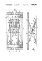
- FIG. 1 is a plan view of a scissor lift embodying the invention in a raised position.
- FIG. 2 is a side elevation of the scissor lift shown in FIG. 1.
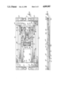
- FIG. 3 is a plan view of the lift shown in FIG. 1 in a collapsed position.
- FIG. 4 is a side elevation of the scissor lift shown in FIG. 3, and showing the lift in a fully collapsed position in phantom.
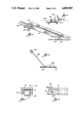
- FIG. 5 is a detailed elevation view of the crank assembly which imparts the initial upward movement to the scissor lift shown in FIGS. 1-4.
- FIG. 6 is an enlarged partial view of the lifting ram and crank assembly of the scissor lift shown in FIGS. 1-4.
- FIG. 7 is an enlarged view of a locking bar assembly included in the scissor lift shown in FIGS. 1-4.
- FIG. 8 is a cross section view taken along line 8--8 in FIG. 3.
- FIG. 9 is a cross-section view taken along line 9--9 in FIG. 8.
- FIG. 1 Illustrated in FIG. 1 is a vehicle scissor lift embodying the invention and including a base 10 supporting a set of inner scissor legs 24 and a pair of outer scissor legs 12.
- Each outer leg 12 includes one end pivotally supported on the base by a pivot pin 14 in turn supported by a bracket or block 16.
- the other end of each leg 12 is provided with a pivoted slider block 18 which slides in and is restrained in a guide track 20 fixed to the elevating platform 22.
- the elevating platform 22 could have other constructions, in the illustrated arrangement it includes a frame comprised of a pair of side bars 21 joined by end bars 23.
- the opposite ends of the frame 22 each support a plurality of pivoting arms 25, in turn, each supporting a support pad 27 adapted to be positioned under the frame of a vehicle for lifting the vehicle.
- Each inner leg 24 includes one end pivotally joined to the platform 22 by a pivot pin 26, and an opposite end of each inner leg 24 is pivotally connected by a pin 29 (FIG. 6) to a slider block 28 which is housed in a slider block guide bracket 30 fixed to the base 10 and supported by the guide bracket 30 for limited linear reciprocal movement.
- the medial portions of the legs 12 and 24 are pivotally interconnected by a pivot Pin 32.
- the pivot pin 32 also supports and serves as a pivot or fulcrum for a pivot bar or crank 34 positioned between the two pairs of legs 12 and 24.
- the pivot bar 34 constitutes a double ended crank having its mid-portion pivoted on Pin 32.
- Each end of the pivot bar includes spaced apart ears 36, nd the space between the ears 36 is adapted to house an end of a piston rod 38 of a hydraulic ram 40.
- a pivot pin 42 extends through all the ears 36 and through the ends of pairs of piston rods 38.
- the opposite ends of the hydraulic rams 40 are pivotally connected to the base 10 by brackets 39 fixed to the base 10 and pivot pins 41 extending through the brackets 39 and through ends of the hydraulic cylinders 40.
- the opposite "end” of the pivot bar or crank 34 includes two more pairs of spaced ears 44 (FIG. 3) which support pivot shafts 46 on which rollers 48 are mounted.
- the rollers 48 engage the upper surface of the floor of the base 10, and the crank 34 is generally horizontally disposed but with pivot pin 42 slightly above the axis of the main pivot pin 32 and above the pivot pin 41 supporting the lower end of the ram 40.
- the point of engagement of the ram 40 with the crank 34 is at a position of maximum advantage and continued extension of the ram 40 will cause the scissor legs 12 and 24 to pivot about the anchor pivots 14 and 26 thereby causing the platform 22 to be elevated.
- the scissor lift also includes a lock bar 43 having one end pivotally joined to the crank 34 by pivot pin 42.
- a lower end 54 (FIG. 7) of the lock bar 43 will drag along the base and will ride over spaced stops 56 fixed to the base 10.
- the lower end 54 of stop bar 42 has to be raised over the stops 56.
- the scissor lift embodying the invention When the scissor lift embodying the invention is in the lowered or retracted position, it has a very low profile. Because the scissor lift has a low profile, it can be installed in a garage or service area on the existing floor, and modification of the floor to recess the scissor lift into the floor is not required. Additionally, because the scissor lift can be readily installed, it can be moved from one service area to another at minimal expense.
- the low profile of the scissor lift is permitted by the provision of the crank arrangement 34 and provides means for initiating upward movement of the scissor lift when the hydraulic ram is in a nearly horizontal position, and the moment arm of the force generated by the hydraulic ram would be otherwise insufficient to cause lifting movement of the lift arms of the scissor lift.
Priority Applications (5)
| Application Number | Priority Date | Filing Date | Title |
|---|---|---|---|
| US07/281,489 US4899987A (en) | 1988-12-08 | 1988-12-08 | Vehicle scissor lift |
| CA000599772A CA1302386C (en) | 1988-12-08 | 1989-05-16 | Vehicle scissor lift |
| DE8989121560T DE68904750T2 (de) | 1988-12-08 | 1989-11-21 | Scherenheber fuer fahrzeuge. |
| EP89121560A EP0374500B1 (de) | 1988-12-08 | 1989-11-21 | Scherenheber für Fahrzeuge |
| AT89121560T ATE85303T1 (de) | 1988-12-08 | 1989-11-21 | Scherenheber fuer fahrzeuge. |
Applications Claiming Priority (1)
| Application Number | Priority Date | Filing Date | Title |
|---|---|---|---|
| US07/281,489 US4899987A (en) | 1988-12-08 | 1988-12-08 | Vehicle scissor lift |
Publications (1)
| Publication Number | Publication Date |
|---|---|
| US4899987A true US4899987A (en) | 1990-02-13 |
Family
ID=23077515
Family Applications (1)
| Application Number | Title | Priority Date | Filing Date |
|---|---|---|---|
| US07/281,489 Expired - Lifetime US4899987A (en) | 1988-12-08 | 1988-12-08 | Vehicle scissor lift |
Country Status (5)
| Country | Link |
|---|---|
| US (1) | US4899987A (de) |
| EP (1) | EP0374500B1 (de) |
| AT (1) | ATE85303T1 (de) |
| CA (1) | CA1302386C (de) |
| DE (1) | DE68904750T2 (de) |
Cited By (35)
| Publication number | Priority date | Publication date | Assignee | Title |
|---|---|---|---|---|
| WO1992004272A1 (en) * | 1990-08-30 | 1992-03-19 | Raine Vierto | Jack |
| EP0613852A1 (de) * | 1993-03-02 | 1994-09-07 | Hydraulik Techniek | Scherenhubtisch |
| WO1996036555A2 (en) * | 1995-05-19 | 1996-11-21 | Eride Rossato | Hydraulic actuator, particularly for a motor vehicle lift |
| WO1999031004A1 (en) * | 1997-12-12 | 1999-06-24 | William Shane Carter | Improved vehicle hoist |
| US6213451B1 (en) * | 1998-09-02 | 2001-04-10 | Gerhard Finkbeiner | Lifting apparatus |
| US6644615B1 (en) | 2002-07-03 | 2003-11-11 | Larin Corporation | Stabilized jack stand |
| US6733227B2 (en) | 2002-02-21 | 2004-05-11 | Engineered Support Systems, Inc. | Elevating lift |
| US20050200091A1 (en) * | 2004-03-12 | 2005-09-15 | Mitchell Knecole A. | Portable tire and wheel lifting apparatus |
| US20070187184A1 (en) * | 2006-02-10 | 2007-08-16 | Nasuti Michelle L | Scissors lift utility tray assembly |
| US20080296542A1 (en) * | 2007-06-04 | 2008-12-04 | Boytcho Manev | Portable vehicle lift |
| US20090020736A1 (en) * | 2006-02-02 | 2009-01-22 | Eride Rossato | Parallelogram Lift for Motor Vehicles |
| US20090078509A1 (en) * | 2007-09-25 | 2009-03-26 | Michael Alf Olsen | Methods and systems for multi-capacity vehicle lift system |
| US20090205907A1 (en) * | 2006-06-21 | 2009-08-20 | Stertil B.V. | Vehicle Elevator and Lift Therein |
| AU2005201658B2 (en) * | 2004-04-27 | 2010-04-01 | Amiata Holdings Pty Ltd | Load elevator |
| US20100243973A1 (en) * | 2007-05-18 | 2010-09-30 | Maha Maschinenbau Haldenwang Gmbh & Co. Kg | Scissor-type lifting platform |
| US20110139549A1 (en) * | 2009-12-16 | 2011-06-16 | Herkules Equipment Corporation | Belt-driven transportation system |
| US20110139548A1 (en) * | 2009-12-16 | 2011-06-16 | Herkules Equipment Corporation | Belt-driven transportation system |
| US20110278517A1 (en) * | 2008-05-16 | 2011-11-17 | Thomas Deuring | Locking devices |
| US20120241698A1 (en) * | 2011-03-25 | 2012-09-27 | Boomerang Systems, Inc. | Scissor lift |
| WO2013059271A1 (en) * | 2011-10-17 | 2013-04-25 | Jlg Industries, Inc. | Remote activation of scissor lift cylinder prop |
| US20140014886A1 (en) * | 2012-07-13 | 2014-01-16 | Rofa Industrial Automation Ag | Lift table control |
| US8733508B2 (en) | 2010-04-02 | 2014-05-27 | Herkules Equipment Corporation | Scissor lift assembly |
| US20150231992A1 (en) * | 2012-08-14 | 2015-08-20 | Johnson Controls Components Gmbh & Co. Kg | Vehicle seat |
| CN105000496A (zh) * | 2015-06-25 | 2015-10-28 | 北京航天发射技术研究所 | 大位移升降连杆式辅助支撑机构 |
| US9296596B2 (en) | 2012-10-15 | 2016-03-29 | Cameron Lanning Cormack | Hybrid wedge jack/scissor lift lifting apparatus and method of operation thereof |
| US9422142B2 (en) | 2013-08-01 | 2016-08-23 | Herkules Equipment Corporation | Scissor-type lift assembly |
| US9474365B2 (en) * | 2015-03-20 | 2016-10-25 | General Electric Company | Tandem spring system |
| US20170340104A1 (en) * | 2016-05-27 | 2017-11-30 | Kelly International Corp. | Lifting platform |
| USD814736S1 (en) * | 2017-03-24 | 2018-04-03 | BendPak, Inc. | Vehicle parking lift support leg |
| US10053343B1 (en) * | 2017-02-07 | 2018-08-21 | Rodney Cameron | Truck bed scissor lift |
| US20180319638A1 (en) * | 2017-05-08 | 2018-11-08 | Nordic Minesteel Technologies Inc. | Telescoping jack for lifting large capacity trucks |
| US11332350B2 (en) * | 2017-05-08 | 2022-05-17 | Nordic Minesteel Technologies Inc. | Telescoping jack for lifting large capacity trucks |
| US11479450B2 (en) * | 2017-05-08 | 2022-10-25 | Nordic Minesteel Technologies Inc. | Telescoping jack for lifting large capacity trucks |
| US11800927B1 (en) | 2015-01-24 | 2023-10-31 | Office Kick, Inc. | Desktop workspace that adjusts vertically |
| US11980289B1 (en) | 2022-10-03 | 2024-05-14 | Office Kick, Inc. | Desktop workspace that adjusts vertically |
Families Citing this family (4)
| Publication number | Priority date | Publication date | Assignee | Title |
|---|---|---|---|---|
| FR2673926B1 (fr) * | 1991-03-14 | 1995-09-01 | Duarib Sa | Plate-forme elevatrice a ciseaux. |
| WO2003022725A1 (en) * | 2001-09-12 | 2003-03-20 | Petrus Johannes Albertus Radyn | Lifting and transfer device for heavy objects |
| FR2856670B1 (fr) * | 2003-06-30 | 2006-12-08 | Alain Bourgeois | Elevateur |
| WO2020073090A1 (en) * | 2018-10-10 | 2020-04-16 | Ferox Advanced Vehicles Corporation Pty Ltd | A structural member |
Citations (4)
| Publication number | Priority date | Publication date | Assignee | Title |
|---|---|---|---|---|
| US3150784A (en) * | 1962-04-27 | 1964-09-29 | Focke Wulf Gmbh | Displaceable lifting platform for automotive vehicles |
| US4221280A (en) * | 1978-05-05 | 1980-09-09 | Advance Lifts, Incorporated | Bi-elevational platform lift |
| US4447042A (en) * | 1981-04-06 | 1984-05-08 | Yasui Sangyo Co., Ltd. | Vehicle lift |
| US4753419A (en) * | 1985-04-16 | 1988-06-28 | Hymo Ab | Hydraulic lifting table |
Family Cites Families (6)
| Publication number | Priority date | Publication date | Assignee | Title |
|---|---|---|---|---|
| GB975154A (en) * | 1961-06-02 | 1964-11-11 | Mann Egerton & Company Ltd | Apparatus for lifting loads |
| GB981991A (en) * | 1962-09-06 | 1965-02-03 | Cotterell & Pither Ltd | Improvements in or relating to lifting platforms |
| DE1280521B (de) * | 1967-06-01 | 1968-10-17 | Ver Flugtechnische Werke Ges M | Sicherheitsabstuetzvorrichtung fuer Hubgeraete, insbesondere fuer Scherenhebebuehnen |
| FR2055883A5 (de) * | 1969-08-05 | 1971-05-14 | Alvarez Suarez Octavie | |
| US4526346A (en) * | 1982-01-18 | 1985-07-02 | G. W. Galloway Company, Inc. | Self-contained elevating table |
| GB2187705B (en) * | 1986-03-14 | 1989-11-15 | Rydal Precision Engineering Co | Lifting apparatus |
-
1988
- 1988-12-08 US US07/281,489 patent/US4899987A/en not_active Expired - Lifetime
-
1989
- 1989-05-16 CA CA000599772A patent/CA1302386C/en not_active Expired - Lifetime
- 1989-11-21 EP EP89121560A patent/EP0374500B1/de not_active Expired - Lifetime
- 1989-11-21 AT AT89121560T patent/ATE85303T1/de not_active IP Right Cessation
- 1989-11-21 DE DE8989121560T patent/DE68904750T2/de not_active Expired - Fee Related
Patent Citations (4)
| Publication number | Priority date | Publication date | Assignee | Title |
|---|---|---|---|---|
| US3150784A (en) * | 1962-04-27 | 1964-09-29 | Focke Wulf Gmbh | Displaceable lifting platform for automotive vehicles |
| US4221280A (en) * | 1978-05-05 | 1980-09-09 | Advance Lifts, Incorporated | Bi-elevational platform lift |
| US4447042A (en) * | 1981-04-06 | 1984-05-08 | Yasui Sangyo Co., Ltd. | Vehicle lift |
| US4753419A (en) * | 1985-04-16 | 1988-06-28 | Hymo Ab | Hydraulic lifting table |
Cited By (63)
| Publication number | Priority date | Publication date | Assignee | Title |
|---|---|---|---|---|
| WO1992004272A1 (en) * | 1990-08-30 | 1992-03-19 | Raine Vierto | Jack |
| EP0613852A1 (de) * | 1993-03-02 | 1994-09-07 | Hydraulik Techniek | Scherenhubtisch |
| WO1996036555A2 (en) * | 1995-05-19 | 1996-11-21 | Eride Rossato | Hydraulic actuator, particularly for a motor vehicle lift |
| WO1996036555A3 (en) * | 1995-05-19 | 1997-01-09 | Eride Rossato | Hydraulic actuator, particularly for a motor vehicle lift |
| WO1999031004A1 (en) * | 1997-12-12 | 1999-06-24 | William Shane Carter | Improved vehicle hoist |
| US6619620B1 (en) | 1997-12-12 | 2003-09-16 | William Shane Carter | Vehicle hoist |
| US6213451B1 (en) * | 1998-09-02 | 2001-04-10 | Gerhard Finkbeiner | Lifting apparatus |
| AU747532B2 (en) * | 1998-09-02 | 2002-05-16 | Gerhard Finkbeiner | Lifting apparatus |
| US6733227B2 (en) | 2002-02-21 | 2004-05-11 | Engineered Support Systems, Inc. | Elevating lift |
| US6644615B1 (en) | 2002-07-03 | 2003-11-11 | Larin Corporation | Stabilized jack stand |
| US7334804B2 (en) * | 2004-03-12 | 2008-02-26 | Mitchell Knecole A | Portable tire and wheel lifting apparatus |
| US20050200091A1 (en) * | 2004-03-12 | 2005-09-15 | Mitchell Knecole A. | Portable tire and wheel lifting apparatus |
| AU2005201658B2 (en) * | 2004-04-27 | 2010-04-01 | Amiata Holdings Pty Ltd | Load elevator |
| US20090020736A1 (en) * | 2006-02-02 | 2009-01-22 | Eride Rossato | Parallelogram Lift for Motor Vehicles |
| US8052122B2 (en) * | 2006-02-02 | 2011-11-08 | O.Me.R. S.P.A. | Parallelogram lift for motor vehicles |
| US20070187184A1 (en) * | 2006-02-10 | 2007-08-16 | Nasuti Michelle L | Scissors lift utility tray assembly |
| US20090205907A1 (en) * | 2006-06-21 | 2009-08-20 | Stertil B.V. | Vehicle Elevator and Lift Therein |
| US8752675B2 (en) | 2006-06-21 | 2014-06-17 | Stertil B.V. | Vehicle elevator and lift therein |
| US8496090B2 (en) * | 2006-06-21 | 2013-07-30 | Stertil B.V. | Vehicle elevator and lift therein |
| US20100243973A1 (en) * | 2007-05-18 | 2010-09-30 | Maha Maschinenbau Haldenwang Gmbh & Co. Kg | Scissor-type lifting platform |
| US20080296542A1 (en) * | 2007-06-04 | 2008-12-04 | Boytcho Manev | Portable vehicle lift |
| US8141851B2 (en) | 2007-06-04 | 2012-03-27 | Boytcho Manev | Portable vehicle lift |
| US20090078509A1 (en) * | 2007-09-25 | 2009-03-26 | Michael Alf Olsen | Methods and systems for multi-capacity vehicle lift system |
| US8469152B2 (en) * | 2007-09-25 | 2013-06-25 | Hunter Engineering Company | Methods and systems for multi-capacity vehicle lift system |
| US8770549B2 (en) * | 2008-05-16 | 2014-07-08 | Maha Maschinenbau Haldenwang Gmbh & Co. Kg | Locking devices |
| US20110278517A1 (en) * | 2008-05-16 | 2011-11-17 | Thomas Deuring | Locking devices |
| US8714524B2 (en) | 2009-12-16 | 2014-05-06 | Herkules Equipment Corporation | Belt-driven transportation system |
| US20110139548A1 (en) * | 2009-12-16 | 2011-06-16 | Herkules Equipment Corporation | Belt-driven transportation system |
| US8662477B2 (en) | 2009-12-16 | 2014-03-04 | Herkules Equipment Corporation | Belt-driven transportation system |
| US20110139549A1 (en) * | 2009-12-16 | 2011-06-16 | Herkules Equipment Corporation | Belt-driven transportation system |
| US8733508B2 (en) | 2010-04-02 | 2014-05-27 | Herkules Equipment Corporation | Scissor lift assembly |
| US8827246B2 (en) * | 2011-03-25 | 2014-09-09 | Parking Source Llc | Scissor lift |
| US20120241698A1 (en) * | 2011-03-25 | 2012-09-27 | Boomerang Systems, Inc. | Scissor lift |
| CN103748031A (zh) * | 2011-10-17 | 2014-04-23 | Jlg工业公司 | 剪叉式升降机缸支架的远程激活 |
| US9670041B2 (en) | 2011-10-17 | 2017-06-06 | Jlg Industries, Inc. | Remote activation of scissor lift cylinder prop |
| WO2013059271A1 (en) * | 2011-10-17 | 2013-04-25 | Jlg Industries, Inc. | Remote activation of scissor lift cylinder prop |
| CN103748031B (zh) * | 2011-10-17 | 2016-01-13 | Jlg工业公司 | 剪叉式升降机缸支架的远程激活 |
| US20140014886A1 (en) * | 2012-07-13 | 2014-01-16 | Rofa Industrial Automation Ag | Lift table control |
| US20150231992A1 (en) * | 2012-08-14 | 2015-08-20 | Johnson Controls Components Gmbh & Co. Kg | Vehicle seat |
| US9440559B2 (en) * | 2012-08-14 | 2016-09-13 | Johnson Controls Components Gmbh & Co. Kg | Vehicle seat |
| US9296596B2 (en) | 2012-10-15 | 2016-03-29 | Cameron Lanning Cormack | Hybrid wedge jack/scissor lift lifting apparatus and method of operation thereof |
| US9422142B2 (en) | 2013-08-01 | 2016-08-23 | Herkules Equipment Corporation | Scissor-type lift assembly |
| US11800927B1 (en) | 2015-01-24 | 2023-10-31 | Office Kick, Inc. | Desktop workspace that adjusts vertically |
| US11849843B1 (en) | 2015-01-24 | 2023-12-26 | Office Kick, Inc. | Desktop workspace that adjusts vertically |
| US11950699B1 (en) | 2015-01-24 | 2024-04-09 | Office Kick, Inc. | Desktop workspace that adjusts vertically |
| US11944196B1 (en) | 2015-01-24 | 2024-04-02 | Office Kick, Inc. | Desktop workspace that adjusts vertically |
| US11925264B1 (en) | 2015-01-24 | 2024-03-12 | Office Kick, Inc. | Desktop workspace that adjusts vertically |
| US11910926B1 (en) | 2015-01-24 | 2024-02-27 | Office Kick, Inc. | Desktop workspace that adjusts vertically |
| US11864654B1 (en) | 2015-01-24 | 2024-01-09 | Office Kick, Inc. | Desktop workspace that adjusts vertically |
| US11857073B1 (en) | 2015-01-24 | 2024-01-02 | Office Kick, Inc. | Desktop workspace that adjusts vertically |
| US9474365B2 (en) * | 2015-03-20 | 2016-10-25 | General Electric Company | Tandem spring system |
| CN105000496A (zh) * | 2015-06-25 | 2015-10-28 | 北京航天发射技术研究所 | 大位移升降连杆式辅助支撑机构 |
| US20170340104A1 (en) * | 2016-05-27 | 2017-11-30 | Kelly International Corp. | Lifting platform |
| US10053343B1 (en) * | 2017-02-07 | 2018-08-21 | Rodney Cameron | Truck bed scissor lift |
| USD814736S1 (en) * | 2017-03-24 | 2018-04-03 | BendPak, Inc. | Vehicle parking lift support leg |
| US10513423B2 (en) * | 2017-05-08 | 2019-12-24 | Nordic Minesteel Technologies Inc. | Telescoping jack for lifting large capacity trucks |
| US11591193B2 (en) * | 2017-05-08 | 2023-02-28 | Nordic Minesteel Technologies Inc. | Telescoping jack for lifting large capacity trucks |
| US11479450B2 (en) * | 2017-05-08 | 2022-10-25 | Nordic Minesteel Technologies Inc. | Telescoping jack for lifting large capacity trucks |
| US20220274815A1 (en) * | 2017-05-08 | 2022-09-01 | Nordic Minesteel Technologies Inc. | Telescoping jack for lifting large capacity trucks |
| US11332350B2 (en) * | 2017-05-08 | 2022-05-17 | Nordic Minesteel Technologies Inc. | Telescoping jack for lifting large capacity trucks |
| AU2017413555B2 (en) * | 2017-05-08 | 2021-02-04 | Nordic Minesteel Technologies Inc. | Telescoping jack for lifting large capacity trucks |
| US20180319638A1 (en) * | 2017-05-08 | 2018-11-08 | Nordic Minesteel Technologies Inc. | Telescoping jack for lifting large capacity trucks |
| US11980289B1 (en) | 2022-10-03 | 2024-05-14 | Office Kick, Inc. | Desktop workspace that adjusts vertically |
Also Published As
| Publication number | Publication date |
|---|---|
| DE68904750D1 (de) | 1993-03-18 |
| EP0374500A1 (de) | 1990-06-27 |
| EP0374500B1 (de) | 1993-02-03 |
| CA1302386C (en) | 1992-06-02 |
| ATE85303T1 (de) | 1993-02-15 |
| DE68904750T2 (de) | 1993-05-19 |
Similar Documents
| Publication | Publication Date | Title |
|---|---|---|
| US4899987A (en) | Vehicle scissor lift | |
| US4890692A (en) | Platform elevating apparatus | |
| US4114854A (en) | Scissors lift work platform | |
| EP1302437A1 (de) | Wagenheber und Hebebühne | |
| CN100551806C (zh) | 升降机 | |
| US3223251A (en) | Displaceable jack for automotive vehicles | |
| US7823698B2 (en) | Three stage mast | |
| US5984270A (en) | Jack safety device | |
| US6244390B1 (en) | Inground lift | |
| US5613575A (en) | Flat-structure lifting platform | |
| US1942945A (en) | Vehicle hoist | |
| US2906373A (en) | Extensible upright for lift trucks | |
| US3727781A (en) | Lift truck load lifting mechanism | |
| EP2147891A1 (de) | Hubarbeitsbühne mit Scherenmechanismus | |
| GB2268467A (en) | Lift. | |
| US4548387A (en) | Mobile hoist | |
| JP3228954B2 (ja) | プラットホーム上に自動車を駐車させるためのパーキング装置 | |
| US3064761A (en) | Lift truck mast | |
| CN108657057A (zh) | 车辆运输车 | |
| JPS6313327Y2 (de) | ||
| US3432006A (en) | Hydraulic hoist for motor vehicles | |
| JPH0518389Y2 (de) | ||
| JPH08333094A (ja) | 車輛整備用リフト | |
| CN216971663U (zh) | 一种垂直升降货梯保护装置及垂直升降货梯 | |
| JPS63154599A (ja) | 自動車用リフト |
Legal Events
| Date | Code | Title | Description |
|---|---|---|---|
| AS | Assignment |
Owner name: HEIN-WERNER CORPORATION, 1005 PERKINS AVENUE WAUKE Free format text: ASSIGNMENT OF ASSIGNORS INTEREST.;ASSIGNOR:CRAIG, THOMAS A.;REEL/FRAME:004986/0280 Effective date: 19881206 Owner name: HEIN-WERNER CORPORATION, A CORP. OF WI, WISCONSIN Free format text: ASSIGNMENT OF ASSIGNORS INTEREST;ASSIGNOR:CRAIG, THOMAS A.;REEL/FRAME:004986/0280 Effective date: 19881206 |
|
| STCF | Information on status: patent grant |
Free format text: PATENTED CASE |
|
| CC | Certificate of correction | ||
| FPAY | Fee payment |
Year of fee payment: 4 |
|
| FPAY | Fee payment |
Year of fee payment: 8 |
|
| FEPP | Fee payment procedure |
Free format text: PAYOR NUMBER ASSIGNED (ORIGINAL EVENT CODE: ASPN); ENTITY STATUS OF PATENT OWNER: LARGE ENTITY |
|
| FPAY | Fee payment |
Year of fee payment: 12 |