US4888662A - High pressure package for pressure transducers - Google Patents
High pressure package for pressure transducers Download PDFInfo
- Publication number
- US4888662A US4888662A US07/282,185 US28218588A US4888662A US 4888662 A US4888662 A US 4888662A US 28218588 A US28218588 A US 28218588A US 4888662 A US4888662 A US 4888662A
- Authority
- US
- United States
- Prior art keywords
- housing
- pressure
- electrical connector
- sensing element
- housing means
- Prior art date
- Legal status (The legal status is an assumption and is not a legal conclusion. Google has not performed a legal analysis and makes no representation as to the accuracy of the status listed.)
- Expired - Lifetime
Links
Images

Classifications
-
- G—PHYSICS
- G01—MEASURING; TESTING
- G01L—MEASURING FORCE, STRESS, TORQUE, WORK, MECHANICAL POWER, MECHANICAL EFFICIENCY, OR FLUID PRESSURE
- G01L9/00—Measuring steady of quasi-steady pressure of fluid or fluent solid material by electric or magnetic pressure-sensitive elements; Transmitting or indicating the displacement of mechanical pressure-sensitive elements, used to measure the steady or quasi-steady pressure of a fluid or fluent solid material, by electric or magnetic means
- G01L9/0041—Transmitting or indicating the displacement of flexible diaphragms
- G01L9/0072—Transmitting or indicating the displacement of flexible diaphragms using variations in capacitance
- G01L9/0075—Transmitting or indicating the displacement of flexible diaphragms using variations in capacitance using a ceramic diaphragm, e.g. alumina, fused quartz, glass
-
- G—PHYSICS
- G01—MEASURING; TESTING
- G01L—MEASURING FORCE, STRESS, TORQUE, WORK, MECHANICAL POWER, MECHANICAL EFFICIENCY, OR FLUID PRESSURE
- G01L19/00—Details of, or accessories for, apparatus for measuring steady or quasi-steady pressure of a fluent medium insofar as such details or accessories are not special to particular types of pressure gauges
- G01L19/14—Housings
- G01L19/142—Multiple part housings
- G01L19/143—Two part housings
Definitions
- This invention relates to a packaging technique for pressure transducers and, more specifically, to such packaging for pressure transducers capable of measuring high pressures in the range of up to about 5000 psi.
- Pressure sensors containing pressure transducers are well known, typical such systems being described in Pat. Nos. 4,716,492 and 4,774,626.
- Pressure transducers of the prior art have generally been fabricated by providing a pressure sensing module in the form of a variable capacitor responsive to pressure which abutted an electronic circuit.
- the electronic circuit sensed the capacitance of the capacitor and provided an output through a plastic electrical connector indicative of the sensed pressure.
- the transducer elements were arranged such that a metal cup assembly having an opening or pressure inlet at one end thereof to receive the fluid under pressure to be measured also included therein the pressure sensing module which was separated from the inlet by a gasket, the electronic circuit and connector also being contained within the metal cup.
- the parts were held together within the metal cup by crimping the metal cup over the plastic connector, the latter being used as a support member.
- the above described pressure transducer provided highly satisfactory results when operated in the low to moderate pressure ranges of up to 500 to 600 psi.
- the above described pressure transducers tended to fail.
- a further point of failure was the plastic connector itself which would tend to shear or compress and release the gasket under the high pressure and release the gas under pressure. It is therefore clear that the prior art pressure transducer of the type described hereinabove was incapable of reliable operation in the high pressure environment.
- a pressure transducer which is capable of withstanding operation, proof and burst pressures in the high pressure ranges of up to about 5000 psi and possibly greater.
- the pressure sensing element is isolated from the connector by being disposed in an all metal surrounded cavity whereby the plastic connector is separated from the pressure sensing element and is not bearing the loads produced by the high pressure fluid. This is accomplished by means of a metal member disposed between the pressure sensing element and the plastic connector whereby the high pressures encountered by the pressure transducer are never applied to the plastic connector.
- a support ring is disposed within the metal cup or can and between the pressure sensing element and the plastic connector with the electronic circuit being disposed in the open portion of the ring between the connector and the pressure sensing element.
- the metal cup or can is crimped over both the metal support ring and the plastic connector disposed therein to hold them in place, fixturing the pressure sensing module securely within the can.
- the gasket and pressure sensing module are as in the above noted prior art with the pressure sensing element abutting the metal support ring which provides the required support.
- the support ring may be open at its center region as above discussed or solid with holes or slots for the electrical feed from the pressure sensing element to the electronic circuitry.
- the can is in one piece with a threaded fitting to mate to the pressure port on the system with which the transducer is used.
- a hex configuration is formed on the part to allow the use of a wrench on the body of the device.
- the use of one piece as opposed to a separate can and port fitting has several advantages. For example, there are fewer parts and assembly operations and a potential leak path that would result from the joining of two parts is eliminated.
- the use of this assembly configuration fixtures the pressure sensing element independently of the connector, yet allows for component loading from one end during assembly, this being advantageous from both cost and complexity standpoints.
- the independent fixturing of the pressure sensing element is maintained.
- a can is used to enclose the pressure sensing element.
- the can is crimped over a hexport which allows mounting to the system being sensed.
- the other end of the can has a raised wall which crimps over the plastic connector, holding the connector in place and enclosing the electronic circuitry. Holes or slots are used in the can as required for electrical feed-throughs and gaskets and/or seals are used, where necessary, to protect the internal components.
- two inexpensive metal cans are used in place of the single can used in the second embodiment.
- the first can is used to fixture the pressure sensing element and crimp over a hexport.
- the second can is used to crimp over the first can at one end and over the plastic connector at the other end to enclose the electronic circuitry and hold the assembly together.
- the embodiments use a flexible circuit as the mounting surface for the electronic circuitry.
- a flexible circuit allows for fold-up assembly during manufacture of the device.
- the flexible circuit allows for direct connections to the pins on the ceramic sensing element and the connector without the addition of wires and the connections required to attach them.
- the flexible circuit also allows for a direct connection from the circuit module to the can. This is done to couple the transducer ground pin to the metal can (system ground) to improve the device's electromagnetic compatibility (EMC) This is accomplished by folding a conductive "tail" from the flexible circuit over the edge of the connector and crimping the can thereover to make electrical contact.
- EMC electromagnetic compatibility
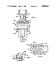
- FIG. 1a is a cross sectional view of a prior art pressure transducer
- FIG. 1b is a view taken along the line 1b--1b of FIG. 1a;
- FIG. 2 is a cross sectional view of a pressure transducer in accordance with a first embodiment of the present invention
- FIG. 3 is a cross sectional view of a pressure transducer in accordance with a second embodiment of the present invention.
- FIG. 4 is a cross sectional view of a pressure transducer in accordance with a third embodiment of the present invention.
- FIG. 5 is a cross sectional view of a pressure transducer in accordance with a fourth embodiment of the present invention.
- FIGS. 1a and 1b there is shown a pressure transducer 1 in accordance with the prior art.
- the transducer includes an outer metal can or cap 3 having a pressure inlet 5 at one surface thereof and a pressure sensing module 7 within the can separated from the inlet by a gasket or O-ring 9.
- Electronic circuitry 11 is positioned in contact with the module 7 and is otherwise surrounded by a plastic electrical connector 13 having a flange portion 15 over which the can 3 is crimped.
- An environmental sealant 17 is positioned at the junction of the can 3 and the connector 13 to prevent contaminants from travelling between the can and connector to the electronic circuitry 11.
- Three terminals 23, 24 and 25 extend outwardly at the rear of the connector and are connected to the electronic circuitry to provide an output therefrom.
- the pressure sensing module 7 is composed of a pair of ceramic layers 19 and 21 which are spaced from each other, each layer having an electrically conductive coating thereon on opposing surfaces to form a capacitor.
- the layer 19 receives the force of fluid entering the pressure inlet 5 thereon and, operating as a diaphragm, varies the distance between electrically conductive coatings to vary the capacitance of the capacitor as a function of applied pressure.
- the above described pressure transducer provides excellent results with pressures at the pressure inlet of up to about 600 psi.
- failures occur due to movement of the crimp over the connector and release of the connector.
- failures occur due to compression of the connector and movement of the gasket between the can and the connector to permit inlet fluid to escape through the rear of the transducer due to leakage.
- FIG. 2 wherein all structure similar to that of FIG. 1 bears the same reference character, there is shown a first embodiment in accordance with the present invention.
- This embodiment is similar to that described with respect to FIGS. 1a and 1b except that a metal support ring 31 capable of withstanding pressures in the range of up to about 5000 psi is disposed between the pressure sensing module 7 and the electrical connector 13 to isolate the electrical connector and the electronic circuitry 11 from the high pressure applied at the pressure inlet 5.
- the can 3 is shown to be crimped over both the support ring 31 as well as the flange 15 of the connector 13.
- an O-ring 9 is used in conjunction with a rigid back-up ring 33, preferably of polytetrafluoroethylene (Teflon) to prevent the O-ring from movement between the sensing element 7 and the can 3.
- a rigid back-up ring 33 preferably of polytetrafluoroethylene (Teflon) to prevent the O-ring from movement between the sensing element 7 and the can 3.
- Teflon polytetrafluoroethylene
- seating systems other than an O-ring such as, for example, gaskets, lip seals, metal seals and the like, can be used.
- the result is that metal has been crimped over metal to provide an ability to withstand the high pressures to be encountered with transducer failure.
- the exterior surface of the pressure inlet 5 can be threaded to receive a mating threaded member (not shown).
- the metal can 41 comprises a set of crimping flanges 43 and 45 at opposite ends thereof, the crimping flanges 43 being crimped over a metallic hexport 47 capable of withstanding pressures of at least 3000 to 5000 psi.
- the hexport 47 includes a central pressure inlet passage 5 for entry into the transducer of the high pressure fluid to be measured.
- a gasket 9 or O-ring and back-up ring 33 is positioned within the can 41 and spaces the pressure sensing element 7 from the hexport 47, the other surface of the element 7 resting against an interior wall of the can.
- the electronic circuitry 11 is positioned external of the can 41 on the wall against which the pressure sensing element 7 rests.
- the plastic electrical connector 13 is disposed over the electronic circuitry 11 with the crimping flange 45 being crimped over the flange 15 of the connector to form the completed pressure transducer. It can be seen that the pressure sensing element as well as all high pressure containing locations have been physically separated from the electronic circuitry as well as the electrical connector by a metal member capable of withstanding the pressures to be encountered.
- FIG. 4 wherein all character references corresponding to those previously used represent the same or similar structure, there is shown a third embodiment in accordance with the present invention.
- This embodiment includes a first interior metal can 61 which includes a flange 63, similar to the flange 43, for crimping over the hexport 47 with pressure inlet 5.
- the pressure sensing module 7 is spaced from the inlet 5 by means of a gasket 9 with the module 7 resting against the interior wall of the can 61 remote from the pressure inlet.
- a second metal can 65 is disposed over the can 61 and includes crimping flanges 67 and 69 at opposite edges thereof.
- the crimping flange 67 is crimped over the can 61 and the crimping flange 63 thereof.
- the electronic circuitry 11 is positioned against the exterior of the can wall supporting the pressure sensing module 7 and is surrounded by the plastic electrical connector 13.
- the flange 69 is crimped over the flange 15 of the connector to provide the completed pressure transducer.
- FIG. 5 wherein all character references corresponding to those previously used represent the same or similar structure, there is shown a fourth embodiment in which provision is made to direct connection between the electronic circuitry 11 and the metal can.
- This is done to provide a direct connection between the circuit module and the can so that the transducer ground pin (circuit ground) can be coupled to the metal can (system ground).
- This improves the electromagnetic compatibility (EMC) of the transducer.
- EMC electromagnetic compatibility
- This is accomplished by folding an electrically conductive tail 71 in the form of a flexible conductor and connected to electronic circuit ground over the flange 15 of the connector 13 and then crimping the metal can over the flange and the tail or flexible conductor 71 which is positioned between the flange and the can. As can be seen, this provides a simple interconnection between system ground and circuit ground, as desired.
Landscapes
- Physics & Mathematics (AREA)
- General Physics & Mathematics (AREA)
- Chemical & Material Sciences (AREA)
- Engineering & Computer Science (AREA)
- Ceramic Engineering (AREA)
- Measuring Fluid Pressure (AREA)
Priority Applications (5)
| Application Number | Priority Date | Filing Date | Title |
|---|---|---|---|
| US07/282,185 US4888662A (en) | 1988-12-08 | 1988-12-08 | High pressure package for pressure transducers |
| US07/366,054 US4903164A (en) | 1988-12-08 | 1989-06-13 | O-ring/back-up ring seal for high pressure transducers |
| JP1314508A JP2854897B2 (ja) | 1988-12-08 | 1989-12-05 | 圧力変換器の高圧パッケージ |
| DE68914264T DE68914264T2 (de) | 1988-12-08 | 1989-12-08 | Hochdruckpackung für Druckwandler. |
| EP89312813A EP0372988B1 (fr) | 1988-12-08 | 1989-12-08 | Emballage à haute pression pour des transducteurs de pression |
Applications Claiming Priority (1)
| Application Number | Priority Date | Filing Date | Title |
|---|---|---|---|
| US07/282,185 US4888662A (en) | 1988-12-08 | 1988-12-08 | High pressure package for pressure transducers |
Related Child Applications (1)
| Application Number | Title | Priority Date | Filing Date |
|---|---|---|---|
| US07/366,054 Continuation-In-Part US4903164A (en) | 1988-12-08 | 1989-06-13 | O-ring/back-up ring seal for high pressure transducers |
Publications (1)
| Publication Number | Publication Date |
|---|---|
| US4888662A true US4888662A (en) | 1989-12-19 |
Family
ID=23080437
Family Applications (1)
| Application Number | Title | Priority Date | Filing Date |
|---|---|---|---|
| US07/282,185 Expired - Lifetime US4888662A (en) | 1988-12-08 | 1988-12-08 | High pressure package for pressure transducers |
Country Status (4)
| Country | Link |
|---|---|
| US (1) | US4888662A (fr) |
| EP (1) | EP0372988B1 (fr) |
| JP (1) | JP2854897B2 (fr) |
| DE (1) | DE68914264T2 (fr) |
Cited By (25)
| Publication number | Priority date | Publication date | Assignee | Title |
|---|---|---|---|---|
| EP0403257A2 (fr) * | 1989-06-13 | 1990-12-19 | Texas Instruments Incorporated | Transducteur à haute pression |
| EP0403256A2 (fr) * | 1989-06-13 | 1990-12-19 | Texas Instruments Incorporated | Fabrication d'un joint comprenant un anneau tonique et un anneau auxiliaire pour transducteurs à haute pression |
| US5060108A (en) * | 1990-01-25 | 1991-10-22 | Texas Instruments Incorporated | Packaging and sealing for pressure transducer |
| EP0570624A2 (fr) * | 1992-05-21 | 1993-11-24 | Fuji Koki Manufacturing Co.,Ltd. | Transducteur capacitif de pression |
| US5349865A (en) * | 1993-08-30 | 1994-09-27 | Kavlico Corporation | Wide-pressure-range, adaptable, simplified pressure transducer |
| US5665921A (en) * | 1995-03-31 | 1997-09-09 | Endress & Hauser Gmbh & Co. | Gas tight pressure sensor sealed with flexible metallic adaptor and having ceramic sensor element |
| US5827972A (en) * | 1993-11-02 | 1998-10-27 | Texas Instruments Incorporated | High pressure sensor apparatus with low cost compact packaging system |
| DE19751096C2 (de) * | 1996-11-20 | 2000-04-06 | Danfoss As | Verbessertes Gehäuse für einen Meßumformer, insbesondere einen Druck-Meßumformer |
| US6076409A (en) * | 1997-12-22 | 2000-06-20 | Rosemount Aerospace, Inc. | Media compatible packages for pressure sensing devices |
| US6122973A (en) * | 1996-09-19 | 2000-09-26 | Hokuriku Electric Industry Co., Ltd. | Electrostatic capacity-type pressure sensor with reduced variation in reference capacitance |
| US6311561B1 (en) | 1997-12-22 | 2001-11-06 | Rosemount Aerospace Inc. | Media compatible pressure sensor |
| US6487911B1 (en) * | 2000-11-21 | 2002-12-03 | Texas Instruments Incorporated | Pressure sensor apparatus |
| US20040129085A1 (en) * | 2002-12-18 | 2004-07-08 | Mundry Sebastian M. | Pressure cell device for measuring hydraulic pressures |
| US20040185702A1 (en) * | 2003-03-19 | 2004-09-23 | Kurtz Anthony D. | Vibration isolated transducer connector |
| WO2008084029A1 (fr) * | 2007-01-12 | 2008-07-17 | Continental Automotive Gmbh | Ensemble boîtier pour capteurs de pression |
| CN104819788A (zh) * | 2014-01-31 | 2015-08-05 | 盾安传感科技有限公司 | 一种密封装置 |
| US20150217416A1 (en) * | 2014-01-31 | 2015-08-06 | Microlux Technology, Inc. | Methods for Fabricating Apparatus Having a Hermetic Seal |
| US20160265997A1 (en) * | 2015-03-12 | 2016-09-15 | Sensata Technologies, Inc. | Pressure transducer |
| US9903777B2 (en) | 2015-03-12 | 2018-02-27 | Sensata Technologies, Inc. | Pressure transducer |
| US10323998B2 (en) | 2017-06-30 | 2019-06-18 | Sensata Technologies, Inc. | Fluid pressure sensor |
| US10488289B2 (en) | 2016-04-11 | 2019-11-26 | Sensata Technologies, Inc. | Pressure sensors with plugs for cold weather protection and methods for manufacturing the plugs |
| US10545064B2 (en) | 2017-05-04 | 2020-01-28 | Sensata Technologies, Inc. | Integrated pressure and temperature sensor |
| US10557770B2 (en) | 2017-09-14 | 2020-02-11 | Sensata Technologies, Inc. | Pressure sensor with improved strain gauge |
| US10724907B2 (en) | 2017-07-12 | 2020-07-28 | Sensata Technologies, Inc. | Pressure sensor element with glass barrier material configured for increased capacitive response |
| US10871413B2 (en) | 2016-04-20 | 2020-12-22 | Sensata Technologies, Inc. | Method of manufacturing a pressure sensor |
Families Citing this family (4)
| Publication number | Priority date | Publication date | Assignee | Title |
|---|---|---|---|---|
| JP2540967Y2 (ja) * | 1991-05-29 | 1997-07-09 | 株式会社 不二工機 | 圧力センサ |
| US6131467A (en) * | 1997-05-09 | 2000-10-17 | Fujikoki Corporation | Pressure sensor including a joint for connecting a housing and connector case together |
| JP2005106796A (ja) * | 2003-08-05 | 2005-04-21 | Fuji Koki Corp | 圧力センサ |
| CA2709495C (fr) | 2007-12-20 | 2016-07-12 | Inficon Gmbh | Agencement pour une cellule de mesure de pression a membrane |
Citations (4)
| Publication number | Priority date | Publication date | Assignee | Title |
|---|---|---|---|---|
| US4128006A (en) * | 1976-12-13 | 1978-12-05 | Bunker Ramo Corporation | Packaging of pressure sensor cells |
| US4329732A (en) * | 1980-03-17 | 1982-05-11 | Kavlico Corporation | Precision capacitance transducer |
| US4414851A (en) * | 1981-08-28 | 1983-11-15 | Motorola, Inc. | Gauge pressure sensor |
| US4716492A (en) * | 1986-05-05 | 1987-12-29 | Texas Instruments Incorporated | Pressure sensor with improved capacitive pressure transducer |
Family Cites Families (3)
| Publication number | Priority date | Publication date | Assignee | Title |
|---|---|---|---|---|
| JPS58731A (ja) * | 1981-06-25 | 1983-01-05 | Matsushita Electric Ind Co Ltd | 静電容量式圧力センサ |
| US4774626A (en) * | 1986-05-05 | 1988-09-27 | Texas Instruments Incorporated | Pressure sensor with improved capacitive pressure transducer |
| DE3786487T2 (de) * | 1986-05-05 | 1993-11-18 | Texas Instruments Inc | Messfühler hoher Präzision. |
-
1988
- 1988-12-08 US US07/282,185 patent/US4888662A/en not_active Expired - Lifetime
-
1989
- 1989-12-05 JP JP1314508A patent/JP2854897B2/ja not_active Expired - Fee Related
- 1989-12-08 EP EP89312813A patent/EP0372988B1/fr not_active Expired - Lifetime
- 1989-12-08 DE DE68914264T patent/DE68914264T2/de not_active Expired - Fee Related
Patent Citations (4)
| Publication number | Priority date | Publication date | Assignee | Title |
|---|---|---|---|---|
| US4128006A (en) * | 1976-12-13 | 1978-12-05 | Bunker Ramo Corporation | Packaging of pressure sensor cells |
| US4329732A (en) * | 1980-03-17 | 1982-05-11 | Kavlico Corporation | Precision capacitance transducer |
| US4414851A (en) * | 1981-08-28 | 1983-11-15 | Motorola, Inc. | Gauge pressure sensor |
| US4716492A (en) * | 1986-05-05 | 1987-12-29 | Texas Instruments Incorporated | Pressure sensor with improved capacitive pressure transducer |
Cited By (43)
| Publication number | Priority date | Publication date | Assignee | Title |
|---|---|---|---|---|
| EP0403257A2 (fr) * | 1989-06-13 | 1990-12-19 | Texas Instruments Incorporated | Transducteur à haute pression |
| EP0403256A2 (fr) * | 1989-06-13 | 1990-12-19 | Texas Instruments Incorporated | Fabrication d'un joint comprenant un anneau tonique et un anneau auxiliaire pour transducteurs à haute pression |
| EP0403257A3 (fr) * | 1989-06-13 | 1991-07-31 | Texas Instruments Incorporated | Transducteur à haute pression |
| EP0403256A3 (fr) * | 1989-06-13 | 1991-09-25 | Texas Instruments Incorporated | Fabrication d'un joint comprenant un anneau tonique et un anneau auxiliaire pour transducteurs à haute pression |
| US5060108A (en) * | 1990-01-25 | 1991-10-22 | Texas Instruments Incorporated | Packaging and sealing for pressure transducer |
| EP0570624A2 (fr) * | 1992-05-21 | 1993-11-24 | Fuji Koki Manufacturing Co.,Ltd. | Transducteur capacitif de pression |
| EP0570624A3 (fr) * | 1992-05-21 | 1994-02-16 | Fuji Koki Mfg | |
| US5343757A (en) * | 1992-05-21 | 1994-09-06 | Fuji Koki Manufacturing Co., Ltd. | Pressure sensor |
| US5349865A (en) * | 1993-08-30 | 1994-09-27 | Kavlico Corporation | Wide-pressure-range, adaptable, simplified pressure transducer |
| WO1995006864A1 (fr) * | 1993-08-30 | 1995-03-09 | Kavlico Corporation | Transducteur de pression simplifie, pouvant s'adapter a des plages de pressions etendues |
| US5827972A (en) * | 1993-11-02 | 1998-10-27 | Texas Instruments Incorporated | High pressure sensor apparatus with low cost compact packaging system |
| US5665921A (en) * | 1995-03-31 | 1997-09-09 | Endress & Hauser Gmbh & Co. | Gas tight pressure sensor sealed with flexible metallic adaptor and having ceramic sensor element |
| US6122973A (en) * | 1996-09-19 | 2000-09-26 | Hokuriku Electric Industry Co., Ltd. | Electrostatic capacity-type pressure sensor with reduced variation in reference capacitance |
| DE19751096C2 (de) * | 1996-11-20 | 2000-04-06 | Danfoss As | Verbessertes Gehäuse für einen Meßumformer, insbesondere einen Druck-Meßumformer |
| US6076409A (en) * | 1997-12-22 | 2000-06-20 | Rosemount Aerospace, Inc. | Media compatible packages for pressure sensing devices |
| US6311561B1 (en) | 1997-12-22 | 2001-11-06 | Rosemount Aerospace Inc. | Media compatible pressure sensor |
| US6487911B1 (en) * | 2000-11-21 | 2002-12-03 | Texas Instruments Incorporated | Pressure sensor apparatus |
| US20040129085A1 (en) * | 2002-12-18 | 2004-07-08 | Mundry Sebastian M. | Pressure cell device for measuring hydraulic pressures |
| US7040174B2 (en) * | 2002-12-18 | 2006-05-09 | Dbt Automation Gmbh | Pressure cell device for measuring hydraulic pressures |
| US7186131B2 (en) * | 2003-03-19 | 2007-03-06 | Kulite Semiconductor Products, Inc. | Vibration isolated transducer connector |
| US20040185702A1 (en) * | 2003-03-19 | 2004-09-23 | Kurtz Anthony D. | Vibration isolated transducer connector |
| WO2008084029A1 (fr) * | 2007-01-12 | 2008-07-17 | Continental Automotive Gmbh | Ensemble boîtier pour capteurs de pression |
| US10094686B2 (en) * | 2014-01-31 | 2018-10-09 | Dunan Sensing Llc | Apparatus for mounting a sensor having a hermetic seal |
| CN104819788A (zh) * | 2014-01-31 | 2015-08-05 | 盾安传感科技有限公司 | 一种密封装置 |
| US20150219517A1 (en) * | 2014-01-31 | 2015-08-06 | Microlux Technology, Inc. | Apparatus Having a Hermetic Seal |
| US20150217416A1 (en) * | 2014-01-31 | 2015-08-06 | Microlux Technology, Inc. | Methods for Fabricating Apparatus Having a Hermetic Seal |
| US20150346002A1 (en) * | 2014-01-31 | 2015-12-03 | Dunan Sensing Llc | Methods for fabricating apparatus having a hermetic seal |
| US20150343575A1 (en) * | 2014-01-31 | 2015-12-03 | Dunan Sensing Llc | Methods for fabricating apparatus having a hermetic seal |
| US10712182B2 (en) | 2014-01-31 | 2020-07-14 | Dunan Sensing Llc | Methods for fabricating an apparatus having a hermetic seal |
| US9581468B2 (en) * | 2014-01-31 | 2017-02-28 | DunAn Sensing, LLC | Methods for fabricating apparatus having a hermetic seal |
| US9625342B2 (en) * | 2014-01-31 | 2017-04-18 | DunAn Sensing, LLC | Sensor housing apparatus providing a hermetic seal |
| US10168191B2 (en) * | 2014-01-31 | 2019-01-01 | Dunan Sensing Llc | Methods for fabricating apparatus having a hermetic seal |
| US9857260B2 (en) * | 2015-03-12 | 2018-01-02 | Sensata Technologies, Inc. | Pressure transducer with multiple joinable portions |
| US9903777B2 (en) | 2015-03-12 | 2018-02-27 | Sensata Technologies, Inc. | Pressure transducer |
| US20160265997A1 (en) * | 2015-03-12 | 2016-09-15 | Sensata Technologies, Inc. | Pressure transducer |
| US10488289B2 (en) | 2016-04-11 | 2019-11-26 | Sensata Technologies, Inc. | Pressure sensors with plugs for cold weather protection and methods for manufacturing the plugs |
| US10871413B2 (en) | 2016-04-20 | 2020-12-22 | Sensata Technologies, Inc. | Method of manufacturing a pressure sensor |
| US10545064B2 (en) | 2017-05-04 | 2020-01-28 | Sensata Technologies, Inc. | Integrated pressure and temperature sensor |
| US11105698B2 (en) | 2017-05-04 | 2021-08-31 | Sensata Technologies, Inc. | Method of assembling a sensing device having a double clinch seal |
| US10323998B2 (en) | 2017-06-30 | 2019-06-18 | Sensata Technologies, Inc. | Fluid pressure sensor |
| US10969288B2 (en) | 2017-06-30 | 2021-04-06 | Sensata Technologies, Inc. | Fluid pressure sensor |
| US10724907B2 (en) | 2017-07-12 | 2020-07-28 | Sensata Technologies, Inc. | Pressure sensor element with glass barrier material configured for increased capacitive response |
| US10557770B2 (en) | 2017-09-14 | 2020-02-11 | Sensata Technologies, Inc. | Pressure sensor with improved strain gauge |
Also Published As
| Publication number | Publication date |
|---|---|
| EP0372988B1 (fr) | 1994-03-30 |
| JP2854897B2 (ja) | 1999-02-10 |
| DE68914264D1 (de) | 1994-05-05 |
| JPH02190731A (ja) | 1990-07-26 |
| DE68914264T2 (de) | 1994-07-21 |
| EP0372988A2 (fr) | 1990-06-13 |
| EP0372988A3 (fr) | 1991-04-03 |
Similar Documents
| Publication | Publication Date | Title |
|---|---|---|
| US4888662A (en) | High pressure package for pressure transducers | |
| US5060108A (en) | Packaging and sealing for pressure transducer | |
| US5000047A (en) | Pressure sensor | |
| EP0403256B1 (fr) | Fabrication d'un joint comprenant un anneau tonique et un anneau auxiliaire pour transducteurs à haute pression | |
| US5043841A (en) | High pressure transducer package | |
| US6848318B2 (en) | Pressure sensor having metallic diaphragm seal joint | |
| US4875135A (en) | Pressure sensor | |
| US6227055B1 (en) | Pressure sensor assembly with direct backside sensing | |
| US7383737B1 (en) | Capacitive pressure sensor | |
| US7036385B2 (en) | Pressure sensor and related method | |
| US7313969B2 (en) | Pressure sensor | |
| US7762139B2 (en) | Pressure transducer apparatus adapted to measure engine pressure parameters | |
| US7183620B2 (en) | Moisture resistant differential pressure sensors | |
| US5827972A (en) | High pressure sensor apparatus with low cost compact packaging system | |
| CN1284163A (zh) | 与介质相容的压力传感器外壳 | |
| US5001934A (en) | Solid state pressure sensor | |
| KR19990082707A (ko) | 압력센서 | |
| EP3538857B1 (fr) | Sous-ensemble de capteur de pression et fabrication | |
| EP0677727A2 (fr) | Assemblage d'un capteur de pression et son procédé de fabrication | |
| US5034848A (en) | Low pressure sensor | |
| JP2600863B2 (ja) | 高圧用半導体式圧力センサの取付け構造 | |
| JPH01248033A (ja) | 半導体式圧力センサ | |
| JPH03237332A (ja) | 半導体圧力センサ | |
| JPH0650270B2 (ja) | 高圧用圧力検出器 | |
| JPH0882563A (ja) | 半導体圧力センサのパッケージング構造 |
Legal Events
| Date | Code | Title | Description |
|---|---|---|---|
| AS | Assignment |
Owner name: TEXAS INSTRUMENTS INCORPORATED, 34 FOREST STREET, Free format text: ASSIGNMENT OF ASSIGNORS INTEREST.;ASSIGNOR:BISHOP, ROBERT P.;REEL/FRAME:004986/0191 Effective date: 19881208 Owner name: TEXAS INSTRUMENTS INCORPORATED, A CORP. OF DE, MAS Free format text: ASSIGNMENT OF ASSIGNORS INTEREST;ASSIGNOR:BISHOP, ROBERT P.;REEL/FRAME:004986/0191 Effective date: 19881208 |
|
| STCF | Information on status: patent grant |
Free format text: PATENTED CASE |
|
| FPAY | Fee payment |
Year of fee payment: 4 |
|
| FPAY | Fee payment |
Year of fee payment: 8 |
|
| FPAY | Fee payment |
Year of fee payment: 12 |
|
| AS | Assignment |
Owner name: MORGAN STANLEY & CO. INCORPORATED, NEW YORK Free format text: SECURITY AGREEMENT;ASSIGNORS:SENSATA TECHNOLOGIES, INC.;SENSATA TECHNOLOGIES FINANCE COMPANY, LLC;REEL/FRAME:017575/0533 Effective date: 20060427 |
|
| AS | Assignment |
Owner name: SENSATA TECHNOLOGIES, INC., MASSACHUSETTS Free format text: ASSIGNMENT OF ASSIGNORS INTEREST;ASSIGNOR:TEXAS INSTRUMENTS INCORPORATED;REEL/FRAME:017870/0147 Effective date: 20060427 |
|
| AS | Assignment |
Owner name: SENSATA TECHNOLOGIES MASSACHUSETTS, INC., MASSACHU Free format text: RELEASE BY SECURED PARTY;ASSIGNOR:MORGAN STANLEY & CO. INCORPORATED;REEL/FRAME:026293/0352 Effective date: 20110512 Owner name: SENSATA TECHNOLOGIES, INC., MASSACHUSETTS Free format text: RELEASE BY SECURED PARTY;ASSIGNOR:MORGAN STANLEY & CO. INCORPORATED;REEL/FRAME:026293/0352 Effective date: 20110512 Owner name: SENSATA TECHNOLOGIES FINANCE COMPANY, LLC, MASSACH Free format text: RELEASE BY SECURED PARTY;ASSIGNOR:MORGAN STANLEY & CO. INCORPORATED;REEL/FRAME:026293/0352 Effective date: 20110512 |